Table of Contents
Advertisement
Quick Links
Advertisement
Table of Contents

Related Manuals for Supero SuperServer 4048B-TRFT


Summary of Contents for Supero SuperServer 4048B-TRFT
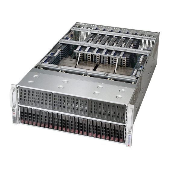
- Page 1 ® UPER SuperServer 4048B-TRFT USER'S MANUAL Revision 1.0a...
- Page 2 The information in this User’s Manual has been carefully reviewed and is believed to be accurate. The vendor assumes no responsibility for any inaccuracies that may be contained in this document, makes no commitment to update or to keep current the information in this manual, or to notify any person or organization of the updates.
-
Page 3: About This Manual
About This Manual This manual is written for professional system integrators and PC technicians. It provides information for the installation and use of the SuperServer 4048B-TRFT. Installation and maintainance should be performed by experienced technicians only. The SuperServer 4048B-TRFT is a high-end server based on the SC418XTA- R3240B 4U rackmount chassis and the quad processor X10QBI serverboard, the X10QBI-MEM1 memory module card and the AOM-X10QBI-A I/O card. - Page 4 SUPERSERVER 4048B-TRFT USER'S MANUAL Chapter 6: Advanced Chassis Setup Refer to Chapter 6 for detailed information on the SC418XTA-R3240B server chassis. You should follow the procedures given in this chapter when installing, removing or reconfi guring SATA or peripheral drives and when replacing system power supply units and cooling fans.
- Page 5 SUPERSERVER 4048B-TRFT USER'S MANUAL Notes...
-
Page 6: Table Of Contents
SUPERSERVER 4048B-TRFT USER'S MANUAL Table of Contents Chapter 1 Introduction Overview ......................1-1 Serverboard Features ..................1-2 Processors ...................... 1-2 Memory ......................1-2 Serial ATA ....................... 1-2 PCI Expansion Slots ..................1-2 Server Chassis Features ................1-3 System Power ....................1-3 SATA Subsystem ..................... - Page 7 Table of Contents Installing the Outer Rails on the Rack ............2-7 Standard Chassis Installation ................. 2-8 Optional Quick Installation Method ..............2-9 Chapter 3 System Interface Overview ......................3-1 Control Panel Buttons ..................3-2 Drive Carrier LEDs ..................3-4 Power Supply LEDs ..................
- Page 8 SUPERSERVER 4048B-TRFT USER'S MANUAL I/O Module Board ..................5-13 Adding PCI Expansion Cards ............... 5-14 Baseboard Details ..................5-15 X10QBi-F Quick Reference................5-16 Connector Defi nitions ..................5-17 5-10 Jumper Settings .................... 5-24 Explanation of Jumpers ................5-24 5-11 Onboard Indicators ..................5-27 5-12 Serial ATA Ports ....................
-
Page 9: Chapter 1 Introduction
Chapter 1 Introduction Overview The SuperServer 4048B-TRFT is a high-end server comprised of four main subsystems: the SC418XTA-R3240B 4U server chassis and the X10QBI quad processor serverboard (baseboard), eight X10QBI-MEM1 memory module cards and one AOM-X10QBI-A I/O card. Please refer to our web site for information on operating systems that have been certifi... -
Page 10: Serverboard Features
SUPERSERVER 4048B-TRFT USER'S MANUAL Serverboard Features At the heart of the SuperServer 4048B-TRFT lies the X10QBI, a quad processor serverboard based on the Intel® C602J chipset and designed to provide maximum performance. The X10QBI acts as a baseboard, into which an I/O card and memory cards may be installed. -
Page 11: Server Chassis Features
Chapter 1: Introduction Server Chassis Features The following is a general outline of the main features of the SC418XTA server chassis. System Power The SC418XTA chassis model includes four 1620W power supplies consisting of two active and two backup power modules. In the unlikely event your power supply fails, replacement is simple and can be accomplished without tools. -
Page 12: Mounting Rails
SUPERSERVER 4048B-TRFT USER'S MANUAL Mounting Rails The SC418XTA includes a set of quick-release rails, and can be placed in a rack for secure storage and use. To setup your rack, follow the instructions included in Chapter 2. Memory Modules The X10QBI-MEM1 memory boards plug directly into the X10QBI baseboard. The memory boards feature a Jordan Creek C104 memory buffer chip. -
Page 13: System Block Diagram
Chapter 1: Introduction Figure 1-1. Intel C602J Chipset: System Block Diagram Note: This is a general block diagram and may not exactly repre- sent the features on your serverboard. See the previous pages for the actual specifi cations of your serverboard. This block diagram is intended for your reference only. -
Page 14: Contacting Supermicro
SUPERSERVER 4048B-TRFT USER'S MANUAL Contacting Supermicro Headquarters Address: Super Micro Computer, Inc. 980 Rock Ave. San Jose, CA 95131 U.S.A. Tel: +1 (408) 503-8000 Fax: +1 (408) 503-8008 Email: marketing@supermicro.com (General Information) support@supermicro.com (Technical Support) Web Site: www.supermicro.com Europe Address: Super Micro Computer B.V. -
Page 15: Chapter 2 Rack Installation
Chapter 2: Server Installation Chapter 2 Rack Installation Overview This chapter provides a quick setup checklist to get your chassis up and running. Following these steps in the order given should enable you to have the system operational within a minimal amount of time. Unpacking the System You should inspect the box which the chassis was shipped in and note if it was damaged in any way. -
Page 16: Warnings And Precautions
SUPERSERVER 4048B-TRFT USER'S MANUAL Warnings and Precautions Rack Precautions • Ensure that the leveling jacks on the bottom of the rack are fully extended to the fl oor with the full weight of the rack resting on them. • In single rack installations, stabilizers should be attached to the rack. -
Page 17: Rack Mounting Considerations
Chapter 2: Server Installation Rack Mounting Considerations Ambient Operating Temperature If installed in a closed or multi-unit rack assembly, the ambient operating tempera- ture of the rack environment may be greater than the ambient temperature of the room. Therefore, consideration should be given to installing the equipment in an environment compatible with the manufacturer’s maximum rated ambient tempera- ture (TMRA). -
Page 18: Rack Mounting Instructions
SUPERSERVER 4048B-TRFT USER'S MANUAL Rack Mounting Instructions This section provides information on installing the chassis into a rack unit with the rails provided. There are a variety of rack units on the market, which may mean that the assembly procedure will differ slightly from the instructions provided. You should also refer to the installation instructions that came with the rack unit you are using. -
Page 19: Releasing The Inner Rail
Chapter 2: Server Installation 3. Secure the rail to the chassis with four screws as illustrated. 4. Repeat steps 1-3 for the other inner rack rail.Locking Tabs Each inner rail has a locking tab. This tab locks the chassis into place when installed and pushed fully into the rack. -
Page 20: Installing The Inner Rails On The Chassis
SUPERSERVER 4048B-TRFT USER'S MANUAL Inner Rails Figure 2-3. Installing the Inner Rails Figure 2-4. Inner Rails Installed on the Chassis Installing The Inner Rails on the Chassis Installing the Inner Rails 1. Confi rm that the left and right inner rails have been correctly identifi ed. -
Page 21: Installing The Outer Rails On The Rack
Chapter 2: Server Installation Figure 2-5. Extending and Releasing the Outer Rails Installing the Outer Rails on the Rack Installing the Outer Rails 1. Press upward on the locking tab at the rear end of the middle rail. 2. Push the middle rail back into the outer rail. 3. -
Page 22: Standard Chassis Installation
SUPERSERVER 4048B-TRFT USER'S MANUAL Ball-Bearing Shuttle Figure 5-6: Installing into a Rack Note: fi gures are for illustrative purposes only. Always install servers into racks from the bottom up. Standard Chassis Installation Installing the Chassis into a Rack 1. Confi rm that the inner rails are properly installed on the chassis. -
Page 23: Optional Quick Installation Method
Chapter 2: Server Installation Optional Quick Installation Method The following quick installation method may be used to install the chassis onto a rack. Installing the Chassis into a Rack 1. Install the whole rail assembly onto the rack as described on page 2-7. 2. - Page 24 SUPERSERVER 4048B-TRFT USER'S MANUAL Notes 2-10...
-
Page 25: Chapter 3 System Interface
Chapter 3: System Interface Chapter 3 System Interface Overview There are several LEDs on the control panel as well as others on the drive carriers to keep you constantly informed of the overall status of the system as well as the activity and health of specifi... -
Page 26: Control Panel Buttons
SUPERSERVER 4048B-TRFT USER'S MANUAL Control Panel Buttons There are two push-buttons included on the control panel: a power button and a reset button. Power The main power button is used to apply or remove power from the power supply to the server system. Turning off system power with this button removes the main power but keeps standby power supplied to the system. -
Page 27: Information Led
Chapter 3: System Interface NIC1 Indicates network activity on GLAN1 when fl ashing. NIC2 Indicates network activity on GLAN2 when fl ashing. Information LED See the table below for the various conditions indicated by the Information LED. Information LED Status Description An overheat condition has occured. -
Page 28: Drive Carrier Leds
SUPERSERVER 4048B-TRFT USER'S MANUAL Power Failure When this LED fl ashes, it indicates a failure in the redundant power supply. Drive Carrier LEDs The chassis includes externally accessable SATA drives. Each drive carrier displays two status LEDs on the front of the carrier. -
Page 29: About Standardized Warning Statements
Chapter 4: Warning Statements for AC Systems Chapter 4 Standardized Warning Statements for AC Systems About Standardized Warning Statements The following statements are industry standard warnings, provided to warn the user of situations which have the potential for bodily injury. Should you have questions or experience difficulty, contact Supermicro's Technical Support department for assistance. - Page 30 SUPERSERVER 4048B-TRFT USER'S MANUAL Warnung WICHTIGE SICHERHEITSHINWEISE Dieses Warnsymbol bedeutet Gefahr. Sie befi nden sich in einer Situation, die zu Verletzungen führen kann. Machen Sie sich vor der Arbeit mit Geräten mit den Gefahren elektrischer Schaltungen und den üblichen Verfahren zur Vorbeugung vor Unfällen vertraut.
- Page 31 Warning Statements for AC Systems ﺟﺴﺪﻳﺔ ﺍﺻﺎﺑﺔ ﺗﺘﺴﺒﺐ ﻓﻲ ﺣﺎﻟﺔ ﻳﻤﻜﻦ ﺃﻥ ﺍﻧﻚ ﻓﻲ ﺧﻄﺮ ﻳﻌﻨﻲ ﻫﺬﺍ ﺍﻟﺮﻣﺰ !ﺗﺤﺬﻳﺮ ﺍﻟﺪﻭﺍﺋﺮ ﺑﺎﻟﻤﺨﺎﻁﺮ ﺍﻟﻨﺎﺟﻤﺔ ﻋﻦ ﻦ ﻋﻠﻰ ﻋﻠﻢ ، ﻛ ﻣﻌﺪﺍﺕ ﺗﻌﻤﻞ ﻋﻠﻰ ﺃﻱ ﻗﺒﻞ ﺃﻥ ﺍﻟﻜﻬﺮﺑﺎﺋﻴﺔ ﺣﻮﺍﺩﺙ ﺃﻱ ﻭﻗﻮﻉ ﻤﻨﻊ ﻟ ﺍﻟﻮﻗﺎﺋﻴﺔ...
-
Page 32: Installation Instructions
SUPERSERVER 4048B-TRFT USER'S MANUAL Installation Instructions Warning! Read the installation instructions before connecting the system to the power source. 警告 将此系统连接电源前,请先阅读安装说明。 警告 將系統與電源連接前,請先閱讀安裝說明。 Warnung Vor dem Anschließen des Systems an die Stromquelle die Installationsanweisungen lesen. ¡Advertencia! Lea las instrucciones de instalación antes de conectar el sistema a la red de alimentación. -
Page 33: Circuit Breaker
Chapter 4: Warning Statements for AC Systems Circuit Breaker Warning! This product relies on the building's installation for short-circuit (overcurrent) protection. Ensure that the protective device is rated not greater than: 250 V, 20 A. 警告 此产品的短路(过载电流)保护由建筑物的供电系统提供,确保短路保护设备的额定电 流不大于250V,20A。 警告 此產品的短路(過載電流)保護由建築物的供電系統提供,確保短路保護設備的額定電 流不大於250V,20A。... -
Page 34: Power Disconnection Warning
SUPERSERVER 4048B-TRFT USER'S MANUAL Waarschuwing Dit product is afhankelijk van de kortsluitbeveiliging (overspanning) van uw electrische installatie. Controleer of het beveiligde aparaat niet groter gedimensioneerd is dan 220V, 20A. Power Disconnection Warning Warning! The system must be disconnected from all sources of power and the power cord removed from the power supply module(s) before accessing the chassis interior to install or remove system components. - Page 35 Chapter 4: Warning Statements for AC Systems ¡Advertencia! El sistema debe ser disconnected de todas las fuentes de energía y del cable eléctrico quitado de los módulos de fuente de alimentación antes de tener acceso el interior del chasis para instalar o para quitar componentes de sistema. Attention Le système doit être débranché...
-
Page 36: Equipment Installation
SUPERSERVER 4048B-TRFT USER'S MANUAL Equipment Installation Warning! Only trained and qualifi ed personnel should be allowed to install, replace, or service this equipment. 警告 只有经过培训且具有资格的人员才能进行此设备的安装、更换和维修。 警告 只有經過受訓且具資格人員才可安裝、更換與維修此設備。 Warnung Das Installieren, Ersetzen oder Bedienen dieser Ausrüstung sollte nur geschultem, qualifi ziertem Personal gestattet werden. -
Page 37: Restricted Area
Chapter 4: Warning Statements for AC Systems Waarschuwing Deze apparatuur mag alleen worden geïnstalleerd, vervangen of hersteld door geschoold en gekwalifi ceerd personeel. Restricted Area Warning! This unit is intended for installation in restricted access areas. A restricted access area can be accessed only through the use of a special tool, lock and key, or other means of security. -
Page 38: Battery Handling
SUPERSERVER 4048B-TRFT USER'S MANUAL אזור עם גישה מוגבלת !אזהרה יש להתקין את היחידה באזורים שיש בהם הגבלת גישה. הגישה ניתנת בעזרת .('כלי אבטחה בלבד )מפתח, מנעול וכד ﻣﺤﻈﻮﺭﺓ ﻣﻨﺎﻁﻖ ﻟﺘﺮﻛﻴﺒﻬﺎ ﻓﻲ ﻫﺬﻩ ﺍﻟﻮﺣﺪﺓ ﺗﺨﺼﻴﺺ ﺗﻢ ،ﺃﺩﺍﺓ ﺧﺎﺻﺔ ﻣﻦ ﺧﻼﻝ ﺍﺳﺘﺨﺪﺍﻡ... - Page 39 Chapter 4: Warning Statements for AC Systems Warnung Bei Einsetzen einer falschen Batterie besteht Explosionsgefahr. Ersetzen Sie die Batterie nur durch den gleichen oder vom Hersteller empfohlenen Batterietyp. Entsorgen Sie die benutzten Batterien nach den Anweisungen des Herstellers. Attention Danger d'explosion si la pile n'est pas remplacée correctement. Ne la remplacer que par une pile de type semblable ou équivalent, recommandée par le fabricant.
-
Page 40: Redundant Power Supplies
SUPERSERVER 4048B-TRFT USER'S MANUAL Redundant Power Supplies Warning! This unit might have more than one power supply connection. All connections must be removed to de-energize the unit. 警告 此部件连接的电源可能不止一个,必须将所有电源断开才能停止给该部件供电。 警告 此裝置連接的電源可能不只一個,必須切斷所有電源才能停止對該裝置的供電。 Warnung Dieses Gerät kann mehr als eine Stromzufuhr haben. Um sicherzustellen, dass der Einheit kein trom zugeführt wird, müssen alle Verbindungen entfernt werden. -
Page 41: Backplane Voltage
Chapter 4: Warning Statements for AC Systems ﺍﻣﺪﺍﺩ ﺍﻟﻄﺎﻗﺔ ﺑﻮﺣﺪﺍﺕ ﻋﺪﺓ ﺍﺗﺼﺎﻻﺕ ﺠﻬﺎﺯ ﺍﻟ ﻳﻜﻮﻥ ﻟﻬﺬﺍ ﻗﺪ ﺍﻟﻜﻬﺮﺑﺎء ﻋﻦ ﻮﺣﺪﺓ ﺍﻟ ﻟﻌﺰﻝ ﻛﺎﻓﺔ ﺍﻻﺗﺼﺎﻻﺕ ﻳﺠﺐ ﺇﺯﺍﻟﺔ Waarschuwing Deze eenheid kan meer dan één stroomtoevoeraansluiting bevatten. Alle aansluitingen dienen verwijderd te worden om het apparaat stroomloos te maken. Backplane Voltage Warning! Hazardous voltage or energy is present on the backplane when the system is... -
Page 42: Comply With Local And National Electrical Codes
SUPERSERVER 4048B-TRFT USER'S MANUAL מתח בפנל האחורי !הרה אז קיימת סכנת מתח בפנל האחורי בזמן תפעול המערכת. יש להיזהר במהלך .העבודה ﺍﻟﻠﻮﺣﺔ ﺃﻭﺍﻟﻄﺎﻗﺔ ﺍﻟﻤﻮﺟﻮﺩﺓ ﻋﻠﻰ ﺍﻟﺘﻴﺎﺭ ﺍﻟﻜﻬﺮﺑﺎﺋﻲ ﻣﻦ ﺧﻄﺮ ﻫﻨﺎﻙ ﻫﺬﺍ ﺍﻟﺠﻬﺎﺯ ﺧﺪﻣﺔ ﻛﻦ ﺣﺬﺭﺍ ﻋﻨﺪ ﻳﻌﻤﻞ ﺍﻟﻨﻈﺎﻡ ﻋﻨﺪﻣﺎ ﻳﻜﻮﻥ... -
Page 43: Product Disposal
Chapter 4: Warning Statements for AC Systems Attention L'équipement doit être installé conformément aux normes électriques nationales et locales. תיאום חוקי החשמל הארצי !אזהרה הציוד חייבת להיות תואמת לחוקי החשמל המקומיים והארציים התקנת ﺍﻟﻤﺘﻌﻠﻘﺔ ﺍﻟﻤﺤﻠﻴﺔ ﻭﺍﻟﻮﻁﻨﻴﺔ ﻘﻮﺍﻧﻴﻦ ﻳﺠﺐ ﺃﻥ ﻳﻤﺘﺜﻞ ﻟﻠ ﺍﻟﻜﻬﺮﺑﺎﺋﻴﺔ... -
Page 44: Hot Swap Fan Warning
SUPERSERVER 4048B-TRFT USER'S MANUAL ¡Advertencia! Al deshacerse por completo de este producto debe seguir todas las leyes y reglamentos nacionales. Attention La mise au rebut ou le recyclage de ce produit sont généralement soumis à des lois et/ou directives de respect de l'environnement. Renseignez-vous auprès de l'organisme compétent. - Page 45 Chapter 4: Warning Statements for AC Systems 警告 當您從機架移除風扇裝置,風扇可能仍在轉動。小心不要將手指、螺絲起子和其他 物品太靠近風扇。 Warnung Die Lüfter drehen sich u. U. noch, wenn die Lüfterbaugruppe aus dem Chassis genommen wird. Halten Sie Finger, Schraubendreher und andere Gegenstände von den Öffnungen des Lüftergehäuses entfernt. ¡Advertencia! Los ventiladores podran dar vuelta cuando usted quite ell montaje del ventilador del chasis.
-
Page 46: Power Cable And Ac Adapter
SUPERSERVER 4048B-TRFT USER'S MANUAL Power Cable and AC Adapter Warning! When installing the product, use the provided or designated connection cables, power cables and AC adaptors. Using any other cables and adaptors could cause a malfunction or a fi re. Electrical Appliance and Material Safety Law prohibits the use of UL or CSA -certifi... - Page 47 Chapter 4: Warning Statements for AC Systems Attention Lors de l'installation du produit, utilisez les bables de connection fournis ou désigné. L'utilisation d'autres cables et adaptateurs peut provoquer un dysfonctionnement ou un incendie. Appareils électroménagers et de loi sur la sécurité Matériel interdit l'utilisation de UL ou CSA câbles certifi...
- Page 48 SUPERSERVER 4048B-TRFT USER'S MANUAL Notes 4-20...
-
Page 49: Chapter 5 Advanced Serverboard Setup
Chapter 5: Advanced Serverboard Setup Chapter 5 Advanced Serverboard Setup This chapter covers the steps required to install the X10QBi-F serverboard into the chassis, connect the data and power cables and install add-on cards. All serverboard jumpers and connections are also described. A layout and quick reference chart are included in this chapter for your reference. -
Page 50: Connecting Cables
(make sure the red wires connect to the pin 1 locations). If you are confi guring the system, keep the airfl ow in mind when routing the cables. The following cables need to be connected for the SuperServer 4048B-TRFT system: •... -
Page 51: Control Panel Connectors And I/O Ports
Chapter 5: Advanced Serverboard Setup Control Panel Connectors and I/O Ports The I/O ports on the are located at the rear of the system. See Figure 5-1 below for the locations of the various I/O ports. Figure 5-1. Rear I/O Ports Back Panel I/O Ports VGA Port X540 10 Gb LAN2 Port... -
Page 52: Connecting The Control Panel
SUPERSERVER 4048B-TRFT USER'S MANUAL Connecting the Control Panel JF1 contains header pins for various front control panel connectors. See Figure 5-1 for the pin locations of the various front control panel buttons and LED indicators. Even and odd numbered pins are on opposite sides of each header. -
Page 53: Processor And Heatsink Installation
Chapter 5: Advanced Serverboard Setup Processor and Heatsink Installation Warning: When handling the processor package, avoid placing direct pressure on the label area. Notes • Always connect the power cord last, and always remove it before adding, removing or changing any hardware components. Make sure that you install the processor into the CPU socket before you install the CPU heatsink. - Page 54 SUPERSERVER 4048B-TRFT USER'S MANUAL 2. Press the second load lever labeled 'Close 1st' to release the load plate that covers the CPU socket from its locking position. Press down on the load Pull the lever away lever labeled 'Close 1st' from the socket 3.
- Page 55 Chapter 5: Advanced Serverboard Setup 5. Use your thumb and index fi nger to hold the CPU on its edges. Align the CPU keys, which are semi-circle cutouts, against the socket keys. Socket Keys CPU Keys 6. Once they are aligned, carefully lower the CPU straight down into the socket. (Do not drop the CPU on the socket.
- Page 56 SUPERSERVER 4048B-TRFT USER'S MANUAL 7. With the CPU inside the socket, inspect the four corners of the CPU to make sure that the CPU is properly installed. 8. Close the load plate with the CPU inside the socket. Lock the lever labeled 'Close 1st' fi...
-
Page 57: Installing A Passive Cpu Heatsink
Chapter 5: Advanced Serverboard Setup Installing a Passive CPU Heatsink 1. Do not apply any thermal grease to the heatsink or the CPU die; the required amount has already been applied. 2. Place the heatsink on top of the CPU so that the four mounting holes are aligned with those on the Serverboard's and the Heatsink Bracket underneath. -
Page 58: Installing Memory
SUPERSERVER 4048B-TRFT USER'S MANUAL Installing Memory Caution: exercise extreme care when installing or removing DIMMs to prevent any possible damage. DIMMs should be installed with the memory card removed from the baseboard. See the tables on page 5-12 for details on populating RDIMM/LDIMM memory. - Page 59 Chapter 5: Advanced Serverboard Setup Figure 5-4. X10QBi-MEM1 Memory Card Image Always install DIMMs in the blue slots fi rst (in order of DIMMA1, DIMMB1, DIMMC1, and DIMMD1). After populating DIMMs on the memory cards, follow the table below to Install one or two populated memory cards for each CPU installed on the baseboard.
-
Page 60: Populating Rdimm/Lrdimm (Ecc) Memory Modules
SUPERSERVER 4048B-TRFT USER'S MANUAL Populating RDIMM/LRDIMM (ECC) Memory Modules Intel E7 Series Processor RDIMM and LRDIMM Memory Confi guration for Performance Mode (2:1) Max Speed (GHz), Voltage (V), Slot per Channel (SPC) Memory and DIMM Per Channel (DPC) Ranks DIMM Capac-... -
Page 61: I/O Module Board
Chapter 5: Advanced Serverboard Setup I/O Module Board Figure 5-5. AOM-X10QBi-A I/O Module Layout AOM-X10QBi-A Rev. 1.00 JPB1 JPG1 JPL1 LAN CTRL LED28 JEDUID1 Jumpers Connectors Location Jumper Description Default Location Connector Description JPL1 LAN Enable/Disable Pins 1-2 (Enabled) JVG1 VGA Port1 JPB1 BMC Enable/Disable... -
Page 62: Adding Pci Expansion Cards
SUPERSERVER 4048B-TRFT USER'S MANUAL Adding PCI Expansion Cards The 4048B-TRFT supports up to 11 PCI Express cards (four x16 and seven x8 slots). Installing an Expansion Card 1. After powering down the system, remove the PCI slot shield. 2. Fully seat the card into the slot, pushing down with your thumbs evenly on both sides of the card. -
Page 63: Baseboard Details
Chapter 5: Advanced Serverboard Setup Baseboard Details Figure 5-7. X10QBi-F Baseboard Layout JIPMB1 FAN10 LED10 LED9 LED8 LED7 LED14 I-SATA5 LED13 LED12 LED11 I-SATA4 JIO1 I-SATA3 JWD1 I-SATA2 JI2C1 LEDIO1 JBT1 JI2C2 I-SATA0 JVRM_I2C1 JPME2 JPME1 LED15 LED28 LED23 JPT1 LED2 LED1 X10QBi... -
Page 64: X10Qbi-F Quick Reference
SUPERSERVER 4048B-TRFT USER'S MANUAL X10QBi-F Quick Reference Jumper Description Default Setting JBT1 Clear CMOS See Section 5-10 C1/JI SMB to PCI-E Slots Pins 2-3 (Disabled) JPB1 (on I/O module) BMC Enabled Pins 1-2 (Enabled) JPG1 (on I/O module) VGA Enable... -
Page 65: Connector Defi Nitions
Chapter 5: Advanced Serverboard Setup Connector Defi nitions ATX Power 24-pin Connector Pin Defi nitions Pin# Defi nition Pin # Defi nition Power Connectors +3.3V +3.3V A 24-pin main power supply connector -12V +3.3V (JPW 1) and six 8-pin power connectors (JPW2-JPW7) are located on the X10DBi PS_ON serverboard. - Page 66 SUPERSERVER 4048B-TRFT USER'S MANUAL PW_ON Connector The Power Button connection is located on pins 1 and 2 of JF1. Momentarily Power Button contacting both pins will power on/off the Pin Defi nitions system. This button can also be confi gured...
- Page 67 Chapter 5: Advanced Serverboard Setup NIC1/2 (LAN1/2) LED Indicators NIC1/2 LEDs Pin The NIC (Network Interface Controller) Defi nitions (JF1) LED cLED indicator onnections for GLAN Pin# Defi nition port 1 are located on pins 11 and 12 of JF1, NIC2 Activity LED and those of the GLAN Port 2 are on pins NIC2 Link LED...
- Page 68 SUPERSERVER 4048B-TRFT USER'S MANUAL Type A USB (USB4/5) Pin Defi nitions Pin# Defi nition Universal Serial Bus (USB) Three Universal Serial Bus headers Ground provide six USB connections on the baseboard (USB 0/1, 2/3, 6/7). Additionally, two Type A USB connectors...
- Page 69 Chapter 5: Advanced Serverboard Setup LAN Ports Pin Defi nition Pin# Defi nition Pin# Defi nition P2V5SB SGND Ethernet LAN Ports TD0+ Act LED Two Ethernet ports (LAN1/LAN2) are TD0- P3V3SB located on the AOM-X10QBi-A I/O TD1+ Link 100 LED (Yel- low, +3V3SB) module.
- Page 70 SUPERSERVER 4048B-TRFT USER'S MANUAL Unit Identifi er Switch/LED A Unit Identifier (UID) switch on the AOM-X10QBi-A I/O module, and two LED indicators are located on the baseboard. The UID switch is located next to the LAN UID Switch ports on the I/O module. The rear UID LED Pin# Defi...
- Page 71 Chapter 5: Advanced Serverboard Setup PWR LED Connector Pin Defi nitions Power LED/Speaker Pin Setting Defi nition On the JD1 header, pins 1-3 are used for Pin 1 Anode (+) power LED indication, and pins 4-7 are for Pin2 Cathode (-) the speaker.
-
Page 72: 5-10 Jumper Settings
SUPERSERVER 4048B-TRFT USER'S MANUAL 5-10 Jumper Settings Connector Pins Explanation of Jumpers To modify the operation of the serverboard, Jumper jumpers can be used to choose between optional settings. Jumpers create shorts between two pins to change the function Setting of the connector. - Page 73 Chapter 5: Advanced Serverboard Setup BMC Enable BMC Enable/Disable Jumper JPB1 allows you to enable the Jumper Settings BMC controller on the X10QBi-A I/O Jumper Setting Defi nition module for IPMI/KVM support. The default Pins 1-2 BMC Enable setting is Normal. Refer to the table on the Pins 2-3 Normal right for jumper settings.
- Page 74 SUPERSERVER 4048B-TRFT USER'S MANUAL Management Engine (ME) Recovery Use jumper JPME1 to select ME Firmware Recovery mode, which will limit resource ME Recovery allocation for essential system operation Jumper Settings only in order to maintain normal power Jumper Setting Defi nition operation and management.
-
Page 75: 5-11 Onboard Indicators
Chapter 5: Advanced Serverboard Setup 5-11 Onboard Indicators Activity LED Link LED LAN LEDs LAN 1/LAN 2 Link LED Two 10 Gb LAN ports (LAN 1/LAN 2) are LED State LED Color Defi nition located on the I/O module. Each Ethernet No Connection or 100 LAN port has two LEDs. -
Page 76: 5-12 Serial Ata Ports
SUPERSERVER 4048B-TRFT USER'S MANUAL 5-12 Serial ATA Ports SATA Port Pin Defi nitions Pin # Defi nition SATA Ports Ground Six Serial ATA ports (I-SATA0~5) are located on the X10QBi baseboard (two Ground SATA 3.0 and four SATA 2.0 ports). See the table on the right for pin defi... -
Page 77: 5-13 Installing Software
Chapter 5: Advanced Serverboard Setup 5-13 Installing Software The Supermicro ftp site contains drivers and utilities for your system at ftp://ftp. supermicro.com. Some of these must be installed, such as the chipset driver. After accessing the ftp site, go into the CDR_Images directory and locate the ISO fi... -
Page 78: Superdoctor® 5
SUPERSERVER 4048B-TRFT USER'S MANUAL SuperDoctor® 5 The Supermicro SuperDoctor 5 is a program that functions in a command-line or web-based interface in Windows and Linux operating systems. The program monitors system health information such as CPU temperature, system voltages, system power consumption, fan speed, and provides alerts via email or Simple Network Management Protocol (SNMP). -
Page 79: 5-14 Onboard Battery
Chapter 5: Advanced Serverboard Setup 5-14 Onboard Battery Caution: There is a danger of explosion if the onboard battery is installed upside down, which will reverse its polarites (see Figure 5-9). This battery must be replaced only with the same or an equivalent type recommended by the manufacturer (CR2032). - Page 80 SUPERSERVER 4048B-TRFT USER'S MANUAL Notes 5-32...
-
Page 81: Chapter 6 Advanced Chassis Setup
Chapter 6: Advanced Chassis Setup Chapter 6 Advanced Chassis Setup This chapter covers the steps required to install components and perform maintenance on the SC418XTA-R3240B chassis. For component installation, follow the steps in the order given to eliminate the most common problems encountered. If some steps are unnecessary, skip ahead to the step that follows. -
Page 82: Control Panel
SUPERSERVER 4048B-TRFT USER'S MANUAL Figure 6-1. Front and Rear Chassis Views Control Panel Hard Drives (24) Power Supplies (4) I/O Ports Control Panel The control panel is located on the front left handle of the chassis. See Chapter 3 for details on the LEDs and the control panel buttons. -
Page 83: Installing Hard Drives
Chapter 6: Advanced Chassis Setup Installing Hard Drives The SC418 supports a total of 24 hard disk drives, which are mounted in drive carriers and reside within the the hard drive bays. These drives are hot-swappable and can be removed or replaced without powering down the chassis. Enterprise SATA HDDs only are recommended. - Page 84 SUPERSERVER 4048B-TRFT USER'S MANUAL Installing a Hard Drive into a Drive Carrier 1. Insert a drive into the carrier with the PCB side facing down and the connector end toward the rear of the carrier. 2. Align the drive in the carrier so that the screw holes of both line up. Note that there are holes in the carrier marked “SATA”...
-
Page 85: Accessing The Inside Of The System
Chapter 6: Advanced Chassis Setup Accessing the Inside of the System Removing the Chassis Cover You will need to access the inside of the system to complete certain procedures such as replacing fans. Removing the Chassis Cover If working with componenets such as memory, processors or heatsinks, start by shutting the system down and disconnecting the AC power cord. -
Page 86: Installing The Air Shroud
SUPERSERVER 4048B-TRFT USER'S MANUAL Installing the Air Shroud Air Shrouds Air shrouds concentrate airfl ow to maximize fan effi ciency. The SC418 chassis air shrouds do not require screws to set them up. Installing the Air Shroud 1. Confi rm that all six fans are in place and working properly. -
Page 87: Cooling System
Chapter 6: Advanced Chassis Setup Cooling System The SC418 chassis contains four 9-cm system fans that provide cooling for the chassis and three 8-cm exhaust fans at the rear of the chassis for expelling hot air. All fans are hot-swappable, there is no need to power down the system when replacing fans. - Page 88 SUPERSERVER 4048B-TRFT USER'S MANUAL Replacing an Exhaust Fan 1. Determine which of the exhaust fans have failed. 2. Remove the cover from the chassis as described previously. 3. Lift the fan housing up and out of the chassis. 4. Remove the failed fan from the fan housing.
-
Page 89: Power Supply
Chapter 6: Advanced Chassis Setup Power Supply The 4048B-TRFT has a redundant, high-effi ciency 1620 Watt power supply. This power supply is auto-switching capable, enabling it to automatically sense and operate at a 100v to 240v input voltage. An amber light will be illuminated on the power supply when the power is off. An illuminated green light indicates that the power supply is operating. - Page 90 SUPERSERVER 4048B-TRFT USER'S MANUAL Notes 6-10...
-
Page 91: Chapter 7 Bios
Chapter 7: BIOS Chapter 7 BIOS Introduction This chapter describes the AMI BIOS setup utility for the X10QBi Platform. It also provides the instructions on how to navigate the AMI BIOS setup utility screens. The AMI ROM BIOS is stored in a Flash EEPROM and can be easily updated. Starting BIOS Setup Utility To enter the AMI BIOS setup utility screens, press the <Del>... -
Page 92: How To Change The Confi Guration Data
SUPERSERVER 4048B-TRFT USER'S MANUAL How To Change the Confi guration Data The confi guration data that determines the system parameters may be changed by entering the AMI BIOS setup utility. This setup utility can be accessed by pressing <Delete> at the appropriate time during system boot. - Page 93 Chapter 7: BIOS The AMI BIOS Main menu displays the following information: System Date/System Time Use this option to change the system date and time using the arrow keys. Enter new values through the keyboard and press <Enter>. Press the <Tab> key to move between fi...
-
Page 94: Advanced Setup Confi Gurations
SUPERSERVER 4048B-TRFT USER'S MANUAL Advanced Setup Confi gurations Select the Advanced tab to access the following submenu items. Boot Features Boot Confi guration Quiet Boot Use this item to select bootup screen display between POST messages and the OEM logo. Select Disabled to display the POST messages. Select Enabled to display the OEM logo instead of the normal POST messages. - Page 95 Chapter 7: BIOS Interrupt 19 Capture Interrupt 19 is the software interrupt that handles the boot disk function. When this item is set to Immediate, the BIOS ROM of the host adaptors will immediately capture Interrupt 19 at bootup and allow the drives that are attached to these host adaptors to function as bootable disks.
- Page 96 SUPERSERVER 4048B-TRFT USER'S MANUAL • Microcode Revision • L1 Cache RAM • L2 Cache RAM • L3 Cache RAM • Processor 0 Version • Processor 1 Version • Processor 2 Version • Processor 3 Version Clock Spread Spectrum Select Enable to allow the BIOS to monitor and attempt to reduce the level of Electromagnetic Interference caused by the components whenever needed.
- Page 97 Chapter 7: BIOS and "Lock Chipset" for Virtualization media support. The default setting is Enable. (Refer to Intel and Microsoft websites for more information.) Select Enable for CPU-related Virtualization support. This feature is used in conjunc- tion with the items: "Clear MCA," "Enable SMX," and "Lock Chipset" for Virtualization media support.
- Page 98 SUPERSERVER 4048B-TRFT USER'S MANUAL DCU IP Prefetcher If this feature is set to Enable, the IP prefetcher in the DCU (Data Cache Unit) will prefetch IP addresses to improve network connectivity and system performance. The options are Enable and Disable.
- Page 99 Chapter 7: BIOS performance. Select Disabled to disable power-saving settings. The options are Disabled, Energy Effi cient, and Custom. If the option is set to Custom, the following items will display: CPU P State Control (Available when Power Technology is set to Custom) EIST (P-states) EIST (Enhanced Intel SpeedStep Technology) allows the system to automatically...
-
Page 100: Cpu T State Control
SUPERSERVER 4048B-TRFT USER'S MANUAL CPU C6 Report (Available when Power Technology is set to Custom) Select Enable to allow the BIOS to report the CPU C6 state (ACPI C3) to the operating system. During the CPU C6 state, power to all cache is turned off. -
Page 101: North Bridge
Chapter 7: BIOS Chipset Confi guration North Bridge This feature is used to confi gure Intel North Bridge settings. Integrated IO Confi guration IIO Confi guration Note: For IIO1 Confi guration/IIO2 Confi guration/IIO3 Confi guration, please refer to Page 4-16. PCIe Train by BIOS Select Yes to resume the operation of a PCI-E device when the device is trapped and put on halt by a "wait-for-BIOS"... - Page 102 SUPERSERVER 4048B-TRFT USER'S MANUAL EV DFX (Device Function On-Hide) Feature When this feature is set to Enable, the EV_DFX Lock Bits that are located on a processor will always remain clear during electric tuning. The options are Dis- able and Enable.
- Page 103 Chapter 7: BIOS Override Max Link Width Use this feature to set the link speed for a selected PCI-E port to override the maximum link-width which was previously set by PCI-Bifurcation. The options are Auto, x1, x2, x4, x8, and x16. PCI-E Port DeEmphasis Use this item to select the De-Emphasis control setting for a PCI-E port specifi...
- Page 104 SUPERSERVER 4048B-TRFT USER'S MANUAL PCI-E Port Select Enable to enable the PCI-E port specifi ed by the user. The options are Auto, Enable, and Disable. Hot Plug Capable Select Enable to enable hot-plugging support for the PCI-E port specifi ed by the user, which will allow the user to replace the device installed on the port without shutting down the system.
- Page 105 Chapter 7: BIOS L0s Support When this item is set to Disable, II0 will never put its transmitter in the L0s state. The options are Disable and Enable. PM ACPI Support Select Enable to generate an _HPGPE message on a PM ACPI event. Select Disable to generate an MSI message.
- Page 106 SUPERSERVER 4048B-TRFT USER'S MANUAL IIO1 Confi guration/IIO2 Confi guration/IIO3 Confi guration IOU0 (II0 PCIE Port 2) This item confi gures the PCI-E port Bifuraction settings for a PCI-E port specifi ed by the user. The options are x4x4x4x4, x4x4x8, x8x4x4, x8x8, x16, and Auto.
- Page 107 Chapter 7: BIOS Hot Plug Capable Select Enable to enable hot-plugging support for the PCI-E port specifi ed by the user to allow the user to replace the device installed on the port without shutting down the system. The options are Disable and Enable. PCI-E Port Link Select Disable to disable the link that is not involved in training activities, but its CFG is still active.
- Page 108 SUPERSERVER 4048B-TRFT USER'S MANUAL PM ACPI Support Select Enable to generate an _HPGPE message on a PM ACPI event. Select Disable to generate an MSI message. The options are Disable and Enable. Gen3 (Generation 3) Eq (Equalization) Mode Use this item to set the "Adaptive Equalization" mode for PCI-E Generation 3 devices.
- Page 109 Chapter 7: BIOS Integrated IO Confi guration Enable I/OAT Select Enable to enable Intel I/OAT (I/O Acceleration Technology), which signifi - cantly reduces CPU overhead by leveraging CPU architectural improvements and freeing the system resource for other tasks. The options are Enable and Disable.
- Page 110 SUPERSERVER 4048B-TRFT USER'S MANUAL VTd (VT-d) Azalea VCp Optimization Select Enable to enable Intel Virtualization Technology (VT-d) Direct I/O support to optimize Azalea VCp performance. The options are Disable and Enable. ® Intel VT for Directed I/O (VT-d) Select Enable to enable Intel Virtualization Technology support for Direct I/O VT-d by reporting the I/O device assignments to the VMM (Virtual Machine Monitor) through the DMAR ACPI Tables.
- Page 111 Chapter 7: BIOS Power Down Unused Ports Select Enable to disable the PCI-E ports that are not active. The options are Disable, Enable, HSX Disable SLD WA Revision Select Auto for the BIOS to automatically update the SLD WA revision status. The default setting is Auto.
- Page 112 SUPERSERVER 4048B-TRFT USER'S MANUAL MMIO P2P Disable Select No to prevent MMIO (Memory-Mapped I/0) P2P (PCI-E device to PCI-E device) signals from crossing the CPU socket. The options are No and Yes. PPIN Opt-in Select Yes to use the Protected-Processor Inventory Number (PPIN) in the system.
- Page 113 Chapter 7: BIOS DDR Speed Use this feature to force a DDR3 memory module to run at a frequency other than what is specifi ed in the specifi cation. The options are Auto, 800, 1067, 1333, 1600, 1867, and 2133. DDR Voltage Level Select Force to 1.50V to force all DDR3 memory modules to operate at 1.50V.
- Page 114 SUPERSERVER 4048B-TRFT USER'S MANUAL Phase Shedding Select Enabled to enable Static Phase-Shedding support for DDR3 memory voltage regulators to improve memory performance. The options are Auto, Disabled and Enabled. Multi-Threaded MRC (Memory Reference Code) Select Enabled for the system to execute multi-threaded memory codes to improve memory performance.
- Page 115 Chapter 7: BIOS Data Scrambling Select Enabled to enable data scrambling to enhance system performance and data integrity. The options are Disabled and Enabled. Scrambling Speed Low Use this feature to set the data scrambling speed to low-32 bits. Enter a value between 0 and 32.
- Page 116 SUPERSERVER 4048B-TRFT USER'S MANUAL MC Channel Hash Mode Select Enabled to support the hash-method-comparison mode for the memory controller to improve memory performance. The options are Enabled and Dis- abled. Unused Memory Channel Input Select Enabled to allow input from unused memory channels. The options are Enabled and Disabled.
- Page 117 Chapter 7: BIOS Promote MEM (Memory) RAS Warnings Select Enabled to promote warnings pertaining to RAS (Reliability, Availability, Serviceability) issues. The options are Enabled and Disabled. Memory Test When this feature is set to Enabled, memory tests will be performed in the sys- tem.
-
Page 118: Memory Topology
SUPERSERVER 4048B-TRFT USER'S MANUAL PSMI Support Select Enabled for Power Supply Management Interface (PSMI) support. The options are Enabled and Disabled. VMSE Clock Stop Select Enabled to de-activate the clock driver for the Intel Scalable Memory Interconnect 2 (Intel SMI 2) controller. The options are Enabled and Disabled. - Page 119 Chapter 7: BIOS Mirroring This item indicates if memory mirroring is supported by the motherboard. Memory mirroring creates a duplicate copy of the data stored in the memory to enhance data security. Sparing This item indicates if memory sparing is supported by the motherboard. Memory sparing enhances system performance.
- Page 120 SUPERSERVER 4048B-TRFT USER'S MANUAL SLIT (System Locality Information Table) One Hop Value Select Enable for the BIOS to build the SLIT table to show the differences be- tween the remote latency ratio and the local latency ratio to further optimize sys- tem performance for Linux Kernel 2.6 or later platforms.
- Page 121 Chapter 7: BIOS Demand Scrub Demand Scrubbing is a process that allows the CPU to correct correctable memory errors found on a memory module. When the CPU or I/O issues a demand-read command, and the read data from memory turns out to be a correctable error, the error is corrected and sent to the requestor (the original source).
-
Page 122: South Bridge
SUPERSERVER 4048B-TRFT USER'S MANUAL Memory Mirroring Select Enable to enable memory-mirroring support which will create a duplicate copy of the data stored in the memory to enhance data security. The options are Disable and Enable. South Bridge This feature is used to confi gure Intel South Bridge settings. - Page 123 Chapter 7: BIOS Port 60/64 Emulation Select Enabled for I/O port 60h/64h emulation support which will provide complete USB keyboard legacy support for the operating system that does not support Legacy USB devices. The options are Disabled and Enabled. USB Hardware Delays and Time-outs USB Transfer Time-out Use this feature sets the USB Transfer Time-out values for control, bulk, and inter- rupt transfers.
- Page 124 SUPERSERVER 4048B-TRFT USER'S MANUAL Alternate ID (Available when RAID is selected in the item above-"Confi gure SATA as") Select Enabled for the port specifi ed by the user to report an alternate ID to the system. The options are Enabled and Disabled.
- Page 125 Chapter 7: BIOS PCIe/PCI/PnP Confi guration PCI Latency Timer Use this feature to set the latency timer of each PCI device installed on a PCI bus. Select 64 to set the PCI latency to 64 PCI clock cycles. The options are 32, 64, 96, 128, 160, 192, 224 and 248 (PCI Bus Clocks).
- Page 126 SUPERSERVER 4048B-TRFT USER'S MANUAL CPU1 Slot 1 PCI-E 3.0 x8 OPROM/CPU1 Slot 2 PCI-E 3.0 x16 OPROM/CPU2 Slot 3 PCI-E 3.0 x8 OPROM/CPU2 Slot 4 PCI-E 3.0 x16 OPROM/CPU2 Slot 5 PCI-E 3.0 x8 OPROM/CPU3 Slot 6 PCI-E 3.0 x8 OPROM/CPU3 Slot 7 PCI-E 3.0 x8 OPROM/CPU4 Slot 8 PCI-E 3.0 x8 OPROM/CPU3 Slot 9 PCI-E 3.0...
-
Page 127: Acpi Settings
Chapter 7: BIOS • Current State • Error Code ACPI Settings Use this feature to confi gure Advanced Confi guration and Power Interface (ACPI) power management settings for your system. Enable ACPI Auto Confi guration Select Enabled to allow BIOS to automatically confi gure ACPI settings. The options are Enabled and Disabled. - Page 128 SUPERSERVER 4048B-TRFT USER'S MANUAL Change Settings This option specifi es the base I/O port address and the Interrupt Request address of Serial Port 1 (COM). Select Disabled to prevent the serial port from accessing any system resources. When this option is set to Disabled, the serial port becomes unavailable.
-
Page 129: Console Redirection Settings
Chapter 7: BIOS COM1 Console Redirection COM 1 Console Redirection This submenu allows the user to confi gure the following Console Redirection set- tings for this port. Console Redirection Select Enabled for Console Redirection support. The options are Enabled and Disabled. - Page 130 SUPERSERVER 4048B-TRFT USER'S MANUAL is even. Select Odd if the parity bit is set to 0, and the number of 1's in data bits is odd. Select None if you do not want to send a parity bit with your data bits in transmission.
- Page 131 Chapter 7: BIOS the OS. When set to Always Enable, legacy console redirection remains enabled when booting the OS. The options are Always Enable and Bootloader. Serial Port for Out-of-Band Management/Windows Emergency Management Services (EMS) The submenu allows the user to confi gure Console Redirection settings to support Out-of-Band Serial Port management.
- Page 132 SUPERSERVER 4048B-TRFT USER'S MANUAL Trusted Computing (Available when a TPM device is detected by the BIOS) Confi guration Security Device Support Select Enabled on this item and enable the TPM jumper on the motherboard to enable onboard security devices to improve data integrity and network security.
-
Page 133: Ipmi
Chapter 7: BIOS Add an Attempt Delete Attempts Change Attempt Order IPMI Select the IPMI (Intelligent Platform Management Interface) tab to access the fol- lowing submenu items. These items indicates your system IPMI fi rmware revision number and status. •... -
Page 134: Security
SUPERSERVER 4048B-TRFT USER'S MANUAL are DHCP and Static. The following items are assigned IP addresses automatically if DHCP is selected, or can be confi gured manually if Static is selected. Station IP Address This item displays the Station IP address for this computer. This should be in decimal and in dotted quad form (i.e., 192.168.10.253). - Page 135 Chapter 7: BIOS Administrator Password Use this feature to set the administrator password which is required to enter the BIOS setup utility. The length of the password should be from 3 characters to 20 characters long. User Password Use this feature to set a user password which is required to log into the system and to enter the BIOS setup utility.
- Page 136 SUPERSERVER 4048B-TRFT USER'S MANUAL Set New PK (Platform Key) Select <Yes> to load default factory platform keys to your system. Select No to load the default settings from other sources. Key Exchange Key Database (KEK) Delete KEK (Key Exchange Key) Select <Yes>...
- Page 137 Chapter 7: BIOS Image Execution Policy Internal FA Select Always Execute for the BIOS to always execute Image-Execution Policy commands on each device path when system security is compromised. The default setting is Always Execute. Option ROM Select Deny Execute to prevent the BIOS from executing Option ROM commands to boot up a system from a network device when system security is compromised.
-
Page 138: Boot
SUPERSERVER 4048B-TRFT USER'S MANUAL Boot This submenu allows the user to confi gure the following boot settings for the system. Set Boot Priority This option prioritizes the order of bootable devices that the system to boot from. Press [ENTER] on each entry from top to bottom to select devices. - Page 139 Chapter 7: BIOS CD/DVD ROM Drive BBS Priorities (Available when a device is installed in this drive) • Boot Order #1 Hard Disk Drive BBS Priorities (Available when a device is installed in this drive) • Boot Order #1 ...
-
Page 140: Save & Exit
SUPERSERVER 4048B-TRFT USER'S MANUAL Save & Exit This submenu allows the user to confi gure the Save and Exit settings for the system. Save Changes and Exit When completing the system confi guration changes, select this option to save the changes and exit from the BIOS setup utility. - Page 141 Chapter 7: BIOS to save confi guration, select Yes to save the changes, or select No to return to the BIOS without making changes. Discard Changes Select this feature and press <Enter> to discard all the changes and return to the BIOS setup.
- Page 142 SUPERSERVER 4048B-TRFT USER'S MANUAL Notes 7-52...
-
Page 143: Appendix A Bios Error Beep Codes
Appendix A: BIOS Error Beep Codes Appendix A BIOS Error Beep Codes During the POST (Power-On Self-Test) routines, which are performed at each system boot, errors may occur. Non-fatal errors are those which, in most cases, allow the system to continue to boot. - Page 144 SUPERSERVER 4048B-TRFT USER'S MANUAL Notes...
-
Page 145: Appendix B System Specifi Cations
24 hot-swap drive bays to house 24 2.5" hard drives. Note: An additional backplane may be installed to support a total of up to 48 2.5" drives. PCI Expansion The SuperServer 4048B-TRFT has four PCI Express 3.0 x16 slots and seven PCI Express 3.0 x8 slots available. Boards One X10QBI baseboard (proprietary form factor) Dimensions: (LxW) 19 x 17 in. - Page 146 SUPERSERVER 4048B-TRFT USER'S MANUAL Chassis SC418XTA-R3240B (4U rackmount) Dimensions: (WxHxD) 7 x 17.2 x 31.3 in. (178 x 437 x 795 mm) Weight Gross (Bare Bone): 150 lbs. (68 kg.) System Cooling The system has four 9-cm system fans and three 8-cm rear exhaust fans (fan...
- Page 147 Appendix B: System Specifi cations Regulatory Compliance Electromagnetic Emissions: FCC Class A, EN 55022 Class A, EN 61000-3-2/-3- 3, CISPR 22 Class A Electromagnetic Immunity: EN 55024/CISPR 24, (EN 61000-4-2, EN 61000-4-3, EN 61000-4-4, EN 61000-4-5, EN 61000-4-6, EN 61000-4-8, EN 61000-4-11) Safety: CSA/EN/IEC/UL 60950-1 Compliant, UL or CSA Listed (USA and Canada), CE Marking (Europe) California Best Management Practices Regulations for Perchlorate Materials:...
- Page 148 SUPERSERVER 4048B-TRFT USER'S MANUAL (continued from front) The products sold by Supermicro are not intended for and will not be used in life support systems, medical equipment, nuclear facilities or systems, aircraft, aircraft devices, aircraft/emergency communication devices or other critical systems whose failure to perform be reasonably expected to result in signifi...
Need help?
Do you have a question about the SuperServer 4048B-TRFT and is the answer not in the manual?
Questions and answers