Table of Contents
Advertisement
Quick Links
XVME-6500A
®
th
Intel
4
Generation Core
Single-Slot VMEbus CPU Module
USER'S MANUAL
ACROMAG INCORPORATED
30765 South Wixom Road
Wixom, MI 48393-2417 U.S.A.
Tel: (248) 295-0310
Email: solutions@acromag.com
Copyright 2015, Acromag, Inc., Printed in the USA.
Data and specifications are subject to change without notice.
8501191A
Advertisement
Table of Contents

Related Manuals for Acromag Intel 4 XVME-6500A


Summary of Contents for Acromag Intel 4 XVME-6500A
- Page 1 Generation Core Single-Slot VMEbus CPU Module USER’S MANUAL ACROMAG INCORPORATED 30765 South Wixom Road Wixom, MI 48393-2417 U.S.A. Tel: (248) 295-0310 Email: solutions@acromag.com Copyright 2015, Acromag, Inc., Printed in the USA. Data and specifications are subject to change without notice. 8501191A...
-
Page 2: Table Of Contents
3.1.4 JTAG VREF Configuration Switch SW5..................... 20 3.1.5 VME PCIe Configuration Switch SW6 ....................21 3.1.6 VME Configuration Switch SW7 ...................... 22 3.2 Power Supply and Management ................. 22 Acromag, Inc. Tel: 248-295-0310 - 1 - - 1 - https://www.acromag.com... - Page 3 3.12.1 Trusted Platform Support ......................32 3.12.2 Password Control .......................... 32 3.13 System Management ....................33 ® 3.13.1 Intel Hyper-Threading Technology ....................33 ® 3.13.2 Enhanced Intel SpeedStep Technology (EIST) ................33 Acromag, Inc. Tel: 248-295-0310 - 2 - - 2 - https://www.acromag.com http://www.acromag.com...
- Page 4 5.1 Service and Repair Assistance ..................44 5.2 Preliminary Service Procedure ..................44 5.3 Where to Get Help ...................... 44 6.0 SPECIFICATIONS ......................44 6.1 Physical ........................44 Acromag, Inc. Tel: 248-295-0310 - 3 - - 3 - https://www.acromag.com http://www.acromag.com...
- Page 5 Failure to do so may cause damage the XVME-6500A in the event of an ESD discharge into the I/O pins..................................64 6.4 Power Requirements ....................65 6.5 Environmental Considerations ..................66 6.6 Reliability Prediction ....................67 6.7 XVME-6500A Certificate of Volatility ................68 Acromag, Inc. Tel: 248-295-0310 - 4 - - 4 - https://www.acromag.com http://www.acromag.com...
- Page 6 8.4.1 Physical ............................82 8.4.2 Connector Information ........................82 8.4.2.1 RJ0 VME Connector (Optional) ..................82 8.4.2.2 RJ2 VME Connector ....................... 83 8.4.2.3 J1 VGA Connector ......................84 Acromag, Inc. Tel: 248-295-0310 - 5 - - 5 - https://www.acromag.com http://www.acromag.com...
- Page 7 8.4.2.14 J2 mSATA Connector ....................91 8.5 Power Requirements ....................92 8.6 Environmental Considerations ..................92 8.7 Reliability Prediction ....................93 8.8 XVME-9640 Certificate of Volatility ................93 REVISION HISTORY ......................94 Acromag, Inc. Tel: 248-295-0310 - 6 - - 6 - https://www.acromag.com http://www.acromag.com...
-
Page 8: General Information
1.2 Preface The information contained in this manual is subject to change without notice, and Acromag, Inc. (Acromag) does not guarantee its accuracy. Acromag makes no warranty of any kind with regard to this material, including, but not limited to, the implied warranties of merchantability and fitness for a particular purpose. -
Page 9: Product Summary
A 26-pin XDP debug connector is also available for connecting compatible emulator tools directly to the CPU. For more information see Intel publication 479493, Shark Bay and Denlow Platforms Debug Port Design Guide. Acromag, Inc. Tel: 248-295-0310 - 8 - - 8 - https://www.acromag.com... -
Page 10: Related Material
Processor PMCs. http://vita.com • ANSI/VITA 42, XMC. http://vita.com • The APTIO Haswell Core BIOS Manual For Acromag Products (8501026). • Intel® document No. 328901, Mobile 4 Generation Intel® Core™ Processor Family Datasheet – Volume 1 of 2, Rev: 002, September, 2013. -
Page 11: Key Features And Benefits
PMC sites when enabled, but the lower site may still contain an XMC module even if the PMC bridge is enabled. • DVI-D – This digital display interface supports connection of both, DVI-D, or HDMI display devices. Acromag, Inc. Tel: 248-295-0310 - 10 - - 10 - https://www.acromag.com http://www.acromag.com... -
Page 12: Intel Qm87 Chipset (Lynx Point) Pch
1000Base-TX connections. Two of these are available on the front panel's RJ Point 5 connector. Two are available on the optional VME P0 connector, for use on a VITA 31.1 Switch-Fabric compliant backplane, or via the optional XVME-9640 RTM module. Acromag, Inc. Tel: 248-295-0310 - 11 - - 11 - https://www.acromag.com... -
Page 13: Nuvoton Nct6106D Super-I/O
The Lower Site can be used for a PMC or XMC module, with the I/O from the J14 connector routed to the VME P0 connector, if installed. Alternatively, I/O from the J16 connector can be routed to the P0 connector. Acromag, Inc. Tel: 248-295-0310 - 12 - - 12 - https://www.acromag.com... - Page 14 USER’S MANUAL XVME-6500A Note: If one PMC and one XMC module are installed in the Expansion Sites, the PMC module must be installed in the Upper Site. Acromag, Inc. Tel: 248-295-0310 - 13 - - 13 - https://www.acromag.com http://www.acromag.com...
-
Page 15: Preparation For Use
It is important that the user employ satisfactory overall system design. It is understood and agreed by the Buyer and Acromag that this is the Buyer's responsibility. WARNING: This board utilizes static sensitive components and should only be handled at a static-safe workstation. -
Page 16: Installing Into A Backplane
7. Connect all remaining peripherals by attaching each interface cable into the appropriate connector on the front of the XVME-6500A board, or on the XVME-9640 Rear Transition Module. Acromag, Inc. Tel: 248-295-0310 - 15 - - 15 - https://www.acromag.com... -
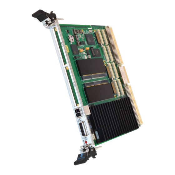
Page 17: Hardware Information And Configuration
USER’S MANUAL XVME-6500A 3.0 HARDWARE INFORMATION AND CONFIGURATION Fig. 3.1.a: XVME-6500A Top View Acromag, Inc. Tel: 248-295-0310 - 16 - - 16 - https://www.acromag.com http://www.acromag.com... -
Page 18: Module Hardware Switch Configuration
OFF the onboard 3.3V regulator is automatically enabled whenever 3.3V is not detected on the backplane. Setting this switch to ON forces the onboard 3.3V regulator to be enabled always. Acromag, Inc. Tel: 248-295-0310 - 17 - - 17 - https://www.acromag.com... -
Page 19: Core Configuration Switch Sw2
SW2-3 and 2-4 are used to override the automatic VGA monitor detection on the VGA ports. If a monitor connected to a port is not automatically recognized, setting the switches as shown will force a particular VGA port to be active. Acromag, Inc. Tel: 248-295-0310 - 18 - - 18 - https://www.acromag.com... -
Page 20: Vme Configuration Switch Sw4
If SW4-3 is on, a VME SYSRESETn assertion on the backplane will cause a local reset. Otherwise, the signal will be isolated from the backplane. If a VME64x backplane is being used, SW4-4 can be used to enable Auto Slot Identification. Acromag, Inc. Tel: 248-295-0310 - 19 - - 19 - https://www.acromag.com... -
Page 21: Jtag Vref Configuration Switch Sw5
Upper Site VREF = 3.3V (J9) JTAG VREF Upper Site VREF = 2.5V Configuration SW5 is used to select the VREF voltage for the XMC/PMC JTAG connections on J8 and J9. Acromag, Inc. Tel: 248-295-0310 - 20 - - 20 - https://www.acromag.com http://www.acromag.com... -
Page 22: Vme Pcie Configuration Switch Sw6
SW6 is for the PCIe memory configuration of the VME bridge. Do not use a prefetchable memory BAR size greater than 1024 Mbytes while in A32 addressing mode (SW6-1 off). Acromag, Inc. Tel: 248-295-0310 - 21 - - 21 - https://www.acromag.com... -
Page 23: Vme Configuration Switch Sw7
P2 I/O to be accessible to the XVME-6500A, as well as allows for the maximum available power from the backplane (90W from 5V and 66W from 3.3V). This is the recommended system for the XVME- 6500A. Acromag, Inc. Tel: 248-295-0310 - 22 - - 22 - https://www.acromag.com... -
Page 24: Programmable Cpu Power Limits
PL1 an equivalent amount of time must be spent below PL1 in order for it to rise again to PL2. The maximum time could be as much 2.5x the value of PL1 Time. Acromag, Inc. Tel: 248-295-0310 - 23 - - 23 - https://www.acromag.com... -
Page 25: Power Management
PMC/XMC modules. More details about programming these power limits using the BIOS setup utility are provided in The Acromag Core BIOS Manual. 3.2.3 Power Management The XVME-6500A module uses the Advanced Configuration and Power Interface (ACPI) 3.0 standard to provide user-managed power via the... -
Page 26: Cpu
More details about this feature are provided in The APTIO Haswell Core BIOS Manual For Acromag Products. 3.3.3 PCI Express Graphics (PEG) The x16 PEG interface is bifurcated into 2 x8 general PCIe ports that connect the Intel®4... -
Page 27: Platform Controller Hub (Pch)
HDA Audio – The HDA audio port is connected to an ALC892 high definition audio codec. Analog stereo line-in and line-out ports are available on the VME P2 connector. Acromag, Inc. Tel: 248-295-0310 - 26 - - 26 - https://www.acromag.com... -
Page 28: System Memory
The processor also integrates a dedicated Mini HD audio controller to drive audio on an HDMI connection. The HD audio controller on the PCH would continue to support down CODECs, and so on. Acromag, Inc. Tel: 248-295-0310 - 27 - - 27 - https://www.acromag.com... -
Page 29: Dvi
3.6.2.3 Integrated Audio (The information below is from Intel® document No. 328901, “Mobile 4th Generation Intel® Core™ Processor Family Datasheet – Volume 1 of 2”, Rev: 002; September, 2013.) Acromag, Inc. Tel: 248-295-0310 - 28 - - 28 - https://www.acromag.com... -
Page 30: Configuring The Primary Display
3.6.3 Configuring the Primary Display To select a specific primary display, refer to The APTIO Haswell Core BIOS Manual For Acromag Products. 3.6.4 Configuring the Video Memory To configure the video memory, refer to The APTIO Haswell Core BIOS Manual For Acromag Products. -
Page 31: General I/O
(POST) codes to the dual 7-segment display. For further information regarding the system BIOS and LPC interfaces, refer to The APTIO Haswell Core BIOS Manual For Acromag Products. 3.9.3 Serial Ports Four 16550‐compatible serial ports are supplied by the NCT6776 Super I/O chip: •... -
Page 32: Usb
(consult factory for more info). For further information regarding BIOS serial port configuration, refer to The APTIO Haswell Core BIOS Manual For Acromag Products. 3.9.4 USB The Intel® Lynx Point PCH has up to two Enhanced Host Controller Interface (EHCI) host controllers to support USB high‐speed signaling on all eight USB... -
Page 33: Battery Powered Real Time Clock (Rtc)
USER’S MANUAL XVME-6500A For information regarding how to boot from the network, refer to The APTIO Haswell Core BIOS Manual For Acromag Products. 3.11 Battery Powered Real Time Clock (RTC) A Motorola® MS146818B‐compatible real‐time clock (RTC) is included in the Intel®... -
Page 34: System Management
The Intel® HT Technology is enabled by default; no action by the operator is required. For further information on disabling support for this technology, refer to The APTIO Haswell Core BIOS Manual For Acromag Products. 3.13.2 Enhanced Intel SpeedStep Technology (EIST) ®... -
Page 35: Intel ® Trusted Execution Technology (Txt)
TXT works in conjunction with the TPM so that the system software may make trust decisions. The Intel TXT feature is enabled by default. For further information on disabling support for this technology, refer to The APTIO Haswell Core BIOS Manual For Acromag Products. 3.13.5 Intel Turbo Boost Technology ®... -
Page 36: Intel ® Active Management Technology
USER’S MANUAL XVME-6500A Refer to The APTIO Haswell Core BIOS Manual For Acromag Products and the appropriate processor Turbo Implementation Guide for more information. 3.13.6 Intel Active Management Technology ® ® (Note: The following information is from Intel publication “External Design ®... -
Page 37: Thermal Monitoring
For further information on configuring the memory bandwidth throttling based on temperature readings from the DIMM’s thermal sensor, refer to The APTIO Haswell Core BIOS Manual For Acromag Products. 3.14.4 Thermal Management Hardware The XVME-6500A is available in air-cooled and extended air-cooled models only. -
Page 38: Watchdog
When the watchdog timer expires the module by default causes a system reset. For further information on the Watchdog feature, refer to The APTIO Haswell Core BIOS Manual For Acromag Products. 3.16 Expansion Sites The XVME-6500A features two expansion sites that allow the board to be customized for a wide array of customer applications. -
Page 39: Pmc Modules
Adapter cables to connect between J8/J9 and a Xilinx USB programmer are available. Please consult factory for more information. VREF voltage on the connector can be selected as either 2.5V or 3.3V using switch SW5. Acromag, Inc. Tel: 248-295-0310 - 38 - - 38 - https://www.acromag.com... -
Page 40: Xbrd-9060 I/O Expander Module
40W. To determine the value to use for PL1: PL1= 90W - 40W – 23.5W = 26.5W. A value no larger than 26.5 should be programmed into the BIOS setup utility for PL1 in this situation. Acromag, Inc. Tel: 248-295-0310 - 39 - - 39 - https://www.acromag.com... - Page 41 5-row with 5V & 3.3V supplied 5V: 20W 3.3V: 63.5W 5-row with 5V only supplied 5V: 17.5W 3.3V: included in 5V 3-row with 5V only supplied ONLY SUPPORTED WITH PL1 lowered Acromag, Inc. Tel: 248-295-0310 - 40 - - 40 - https://www.acromag.com http://www.acromag.com...
-
Page 42: Vme Interface
TOGGLE Fast – LTSSM L1 states ON – any other state *Refer to PCI Express specification. For driver information on the FPGA VME Bridge please refer to ALTHEA 7910 Application Programming Interface manual. Acromag, Inc. Tel: 248-295-0310 - 41 - - 41 - https://www.acromag.com http://www.acromag.com... -
Page 43: Front Panel Layout
RESET Switch: The front panel switch can be configured to cause a local reset and also may reset the VME backplane, depending on the configuration of SW1-1 and SW4-6. Acromag, Inc. Tel: 248-295-0310 - 42 - - 42 - https://www.acromag.com http://www.acromag.com... -
Page 44: Firmware/Bios Information And Configuration
Note the mezzanine must support use of the MVMRO signal. • The rear DVI-D port can be enabled/disabled. 4.2 Drivers and Utilities Drivers and Utilities for the XVME-6500A can be downloaded from Acromag's website at https://www.acromag.com/. Acromag, Inc. Tel: 248-295-0310... -
Page 45: Service And Repair
5.3 Where to Get Help If the problem persists, the next step should be to visit the Acromag website at https://www.acromag.com. Our web site contains the most up-to-date product and software information. -
Page 46: Connector Information
6.2.3 J17 FPGA-based VME Bridge Programming Header This header is used to program the 128Mb SPI Flash EPROM containing the FPGA firmware and is for factory use only. SIGNAL JTAG_TDI JTAG_TDO JTAG_TCK JTAG_TMS JTAG_VREF Acromag, Inc. Tel: 248-295-0310 - 45 - - 45 - https://www.acromag.com http://www.acromag.com... -
Page 47: Vme Interface
+3.3V_TO_RTM is fused by a 2A slow blow fuse on the SBC. +3.3V_TO_RTM is used by ethernet activity LEDs and MSATA modules on the XVME-9640 RTM module. Care should be taken to not exceed 2A. Acromag, Inc. Tel: 248-295-0310 - 46 - - 46 - https://www.acromag.com... -
Page 48: P1 Vme Connector
+3.3V IRQ4# IRQ3# +3.3V IRQ2# IRQ1# +3.3V -12V +12V NC = NO CONNECT The XVME-6500A will use +3.3V from the backplane, if present, but it is not required. Acromag, Inc. Tel: 248-295-0310 - 47 - - 47 - https://www.acromag.com http://www.acromag.com... -
Page 49: P2 Vme Connector (Standard I/O)
UPR_IO22_N UPR_IO14_P UPR_IO7_P UPR_IO30_P VME_D30 UPR_IO22_P UPR_IO14_N UPR_IO30_N VME_D31 UPR_IO15_N UPR_IO15_P UPR_IO7_N UPR_IO31_P UPR_IO23_P UPR_IO31_N UPR_IO23_N TX- and RX- only used when serial port is in RS-422/RS-485 mode Acromag, Inc. Tel: 248-295-0310 - 48 - - 48 - https://www.acromag.com http://www.acromag.com... -
Page 50: P2 Vme Connector (Xvme-6300 Compatible I/O - Consult Factory For This Option)
COM4_DTR# GPOUT1 GPOUT2 GPOUT3 NC = NO CONNECT TX- and RX- only used when serial ports is in RS-422/RS-485 mode. RTS# and DSR# are available in RS-232 mode. Acromag, Inc. Tel: 248-295-0310 - 49 - - 49 - https://www.acromag.com http://www.acromag.com... -
Page 51: Lower Pmc/Xmc Site
IRDY# DEVSEL# PCIXCAP PU to 3.3V +3.3V AD(15) AD(12) AD(11) AD(9) C/BE(0)# AD(6) AD(5) AD(4) +3.3V AD(3) AD(2) AD(1) AD(0) REQ64# NC = NO CONNECT PU = PULLUP Acromag, Inc. Tel: 248-295-0310 - 50 - - 50 - https://www.acromag.com http://www.acromag.com... -
Page 52: J12 Lower Pmc Site Pci-X Connector
AD(20) AD(18) AD(16) C/BE(2)# TRDY# +3.3V STOP# PERR# +3.3V SERR# C/BE(1)# AD(14) AD(13) M66EN AD(10) AD(8) +3.3V AD(7) +3.3V ACK64# +3.3V NC = NO CONNECT PU = PULLUP Acromag, Inc. Tel: 248-295-0310 - 51 - - 51 - https://www.acromag.com http://www.acromag.com... -
Page 53: J13 Lower Pmc Site Pci-X Connector
AD(53) AD(52) AD(51) AD(50) AD(49) AD(48) AD(47) AD(46) AD(45) +3.3V AD(44) AD(43) AD(42) AD(41) AD(40) AD(39) AD(38) AD(37) AD(36) AD(35) AD(34) AD(33) +3.3V AD(32) NC = NO CONNECT Acromag, Inc. Tel: 248-295-0310 - 52 - - 52 - https://www.acromag.com http://www.acromag.com... -
Page 54: J14 Lower Pmc Site Rear-I/O Connector
LWR_IO18_P LWR_IO19_P LWR_IO18_N LWR_IO19_N LWR_IO20_P LWR_IO21_P LWR_IO20_N LWR_IO21_N LWR_IO22_P LWR_IO23_P LWR_IO22_N LWR_IO23_N LWR_IO24_P LWR_IO25_P LWR_IO24_N LWR_IO25_N LWR_IO26_P LWR_IO27_P LWR_IO26_N LWR_IO27_N LWR_IO28_P LWR_IO29_P LWR_IO28_N LWR_IO29_N LWR_IO30_P LWR_IO31_P LWR_IO30_N LWR_IO31_N Acromag, Inc. Tel: 248-295-0310 - 53 - - 53 - https://www.acromag.com http://www.acromag.com... -
Page 55: J15 Lower Xmc Site Pcie Connector
This 6-pin Molex 78171-5006 connector carries the Lower PMC or XMC module's JTAG interface. The VREF voltage can be selected between 2.5V, or 3.3V with SW5. SIGNAL JTAG_TDI JTAG_TDO JTAG_TCK JTAG_TMS JTAG_VREF Acromag, Inc. Tel: 248-295-0310 - 54 - - 54 - https://www.acromag.com http://www.acromag.com... -
Page 56: J16 Lower Xmc Site Rear I/O Connector
LWR_IO24_N LWR_IO25_N LWR_IO14_P LWR_IO14_N LWR_IO24_P LWR_IO15_P LWR_IO15_N LWR_IO25_P LWR_IO22_N LWR_IO23_N LWR_IO16_P LWR_IO16_N LWR_IO22_P LWR_IO17_P LWR_IO17_N LWR_IO23_P LWR_IO20_N LWR_IO21_N LWR_IO18_P LWR_IO18_N LWR_IO20_P LWR_IO19_P LWR_IO19_N LWR_IO21_P NC = NO CONNECT Acromag, Inc. Tel: 248-295-0310 - 55 - - 55 - https://www.acromag.com http://www.acromag.com... -
Page 57: Upper Pmc/Xmc Site
IRDY# DEVSEL# PCIXCAP PU to 3.3V +3.3V AD(15) AD(12) AD(11) AD(9) C/BE(0)# AD(6) AD(5) AD(4) +3.3V AD(3) AD(2) AD(1) AD(0) REQ64# NC = NO CONNECT PU = PULLUP Acromag, Inc. Tel: 248-295-0310 - 56 - - 56 - https://www.acromag.com http://www.acromag.com... -
Page 58: J22 Upper Pmc Site Pci-X Connector
AD(20) AD(18) AD(16) C/BE(2)# TRDY# +3.3V STOP# PERR# +3.3V SERR# C/BE(1)# AD(14) AD(13) M66EN AD(10) AD(8) +3.3V AD(7) +3.3V ACK64# +3.3V NC = NO CONNECT PU = PULLUP Acromag, Inc. Tel: 248-295-0310 - 57 - - 57 - https://www.acromag.com http://www.acromag.com... -
Page 59: J23 Upper Pmc Site Pci-X Connector
AD(53) AD(52) AD(51) AD(50) AD(49) AD(48) AD(47) AD(46) AD(45) +3.3V AD(44) AD(43) AD(42) AD(41) AD(40) AD(39) AD(38) AD(37) AD(36) AD(35) AD(34) AD(33) +3.3V AD(32) NC = NO CONNECT Acromag, Inc. Tel: 248-295-0310 - 58 - - 58 - https://www.acromag.com http://www.acromag.com... -
Page 60: J24 Upper Pmc Site Rear I/O Connector
UPR_IO18_P UPR_IO19_P UPR_IO18_N UPR_IO19_N UPR_IO20_P UPR_IO21_P UPR_IO20_N UPR_IO21_N UPR_IO22_P UPR_IO23_P UPR_IO22_N UPR_IO23_N UPR_IO24_P UPR_IO25_P UPR_IO24_N UPR_IO25_N UPR_IO26_P UPR_IO27_P UPR_IO26_N UPR_IO27_N UPR_IO28_P UPR_IO29_P UPR_IO28_N UPR_IO29_N UPR_IO30_P UPR_IO31_P UPR_IO30_N UPR_IO31_N Acromag, Inc. Tel: 248-295-0310 - 59 - - 59 - https://www.acromag.com http://www.acromag.com... -
Page 61: J25 Upper Xmc Site Pcie Connector
This 6-pin Molex 78171-5006 connector carries the Lower PMC or XMC module's JTAG interface. The VREF voltage can be selected between 2.5V, or 3.3V with SW5. SIGNAL JTAG_TDI JTAG_TDO JTAG_TCK JTAG_TMS JTAG_VREF Acromag, Inc. Tel: 248-295-0310 - 60 - - 60 - https://www.acromag.com http://www.acromag.com... -
Page 62: J7 Upper Pmc/Xmc Site Expansion Connector
+3.3V +3.3V +1.5V NC = NO CONNECT ENET1 signals may instead be switched to XBRD-9060 I/O Expander module, if installed. ENET1_SEL# Auto-switches ENET1 signals to XBRD-9060 when low. Acromag, Inc. Tel: 248-295-0310 - 61 - - 61 - https://www.acromag.com http://www.acromag.com... -
Page 63: Front Panel Connectors
Note: The DB-9 serial connector on this dongle cable is wired as a DTE port. SIGNAL USB0_P USB0_N +5V USB POWER VGA_I2C_DAT VGA_RED VGA_GRN VGA_BLUE USB1_P USB1_N +5V VGA POWER VGA_I2C_CLK GND_RED GND_GREEN GND_BLUE COM1_CTS# COM1_RTS# COM1_DSR# COM1_DTR# COM1_TXD COM1_RXD VGA_VSYNC VGA_HSYNC Acromag, Inc. Tel: 248-295-0310 - 62 - - 62 - https://www.acromag.com http://www.acromag.com... -
Page 64: J4 Dual Ethernet Rj Point 5 Connector
6.2.8 P3 CPU Fan Connector This 5-pin connector, Molex 53398-0571, can be used to power a 5V fan in situations where more cooling is necessary. SIGNAL NO CONNECT FAN TACH FAN PWM Acromag, Inc. Tel: 248-295-0310 - 63 - - 63 - https://www.acromag.com http://www.acromag.com... -
Page 65: P2 I/O Signal Requirements
It is strongly suggested that ESD protection be included in interface circuitry on the VGA and USB ports. Failure to do so may cause damage the XVME- 6500A in the event of an ESD discharge into the I/O pins. Acromag, Inc. Tel: 248-295-0310 - 64 - - 64 - https://www.acromag.com... -
Page 66: Power Requirements
Operating System. Passmark Burn-In test running the following tests: CPU, Memory, 2D Graphics, 3D Graphics, Disk, and Network. 16GB RAM. 1 connected SATA device, one USB keyboard, one USB mouse, VGA monitor, DVI monitor. No PMC/XMC cards installed. Acromag, Inc. Tel: 248-295-0310 - 65 - - 65 - https://www.acromag.com... -
Page 67: Environmental Considerations
Conducted RF Immunity (CRFI), per IEC 61000-4-6, Class A. • Emissions per EN 61000-6-4: Enclosure Port, per CISPR 16-2-3 Class A. Low Voltage AC Mains Port, per CISPR 16-2-3 Class A. Acromag, Inc. Tel: 248-295-0310 - 66 - - 66 - https://www.acromag.com http://www.acromag.com... -
Page 68: Reliability Prediction
FN2. Per MIL-HDBK-217, Ground Benign, Controlled, G Temperature MTBF (Hours) MTBF (Years) Failure Rate (FIT 25°C 201,131 23.0 4,971.9 40°C 147,044 16.8 6,800.7 FIT is Failures in 10 hours. Acromag, Inc. Tel: 248-295-0310 - 67 - - 67 - https://www.acromag.com http://www.acromag.com... -
Page 69: Xvme-6500A Certificate Of Volatility
Clear Flash memory by □ No erasing all sectors of the Flash Acromag Representative Name: Title: Email: Office Phone: Office Fax: Russ Nieves Dir. of Sales solutions@acromag.com 248-624-0310 248-624-9234 Marketing Acromag, Inc. Tel: 248-295-0310 - 68 - - 68 - https://www.acromag.com http://www.acromag.com... -
Page 70: Xbrd-9060 I/O Expander Accessory Module
RAID0/1 array if redundancy or extra speed is desired. 7.1 Ordering Information The XBRD-9060 is only available in a lead-free solder model. The full model number is XBRD-9060-LF. Acromag, Inc. Tel: 248-295-0310 - 69 - - 69 - https://www.acromag.com... -
Page 71: Hardware Information And Configuration
Once the module is seated in the connector, install the four screws provided from the back side of the XVME-6500A. In a high-vibration environment the addition of a removable thread locker, such as Loctite 242, is recommended. Acromag, Inc. Tel: 248-295-0310 - 70 - - 70 - https://www.acromag.com... -
Page 72: Specifications
The XBRD-9060 dimensions are shown below: Length 128.0 mm (5.039 in) Width 74..0 mm (2.913 in) Height from XVME-6500A (includes PCB) 12.6 mm (0.496 in) Unit Weight 2.3 oz (0.067 kg) Acromag, Inc. Tel: 248-295-0310 - 71 - - 71 - https://www.acromag.com http://www.acromag.com... -
Page 73: Connector Information
+3.3V ENET1_SEL# +3.3V +3.3V +1.5V NC = NO CONNECT ENET1 signals are not available when is in position 2-3. ENET1_SEL# enables ENET1 signals when is in position 1-2. Acromag, Inc. Tel: 248-295-0310 - 72 - - 72 - https://www.acromag.com http://www.acromag.com... -
Page 74: J7 Ethernet Connector
SIGNAL COM3_RXD COM3_TXD 7.5.2.4 RS-232 Serial Adapter Cable Use the included shielded adapter cable to have a standard DB-9 connector wired as a DTE port. SIGNAL COM3_TXD COM3_RXD Acromag, Inc. Tel: 248-295-0310 - 73 - - 73 - https://www.acromag.com http://www.acromag.com... -
Page 75: J4 Usb 2.0 Connector
Note: Even though the connector is a USB 3.0 connector, it will only function at USB 2.0 or lower speeds. There is no USB 3.0 superspeed signal connection. SIGNAL +5V USB POWER USB3_N USB3_P Acromag, Inc. Tel: 248-295-0310 - 74 - - 74 - https://www.acromag.com http://www.acromag.com... -
Page 76: J1 Msata Connector
XBRD-9060. SIGNAL SIGNAL +3.3V +1.5V PLT_RST# SATA0_RX_N +3.3V SATA0_RX_P +1.5V SMB_CLK SATA0_TX_N SMB_DATA SATA0_TX_P +3.3V +3.3V +1.5V +3.3V NC = NO CONNECT Acromag, Inc. Tel: 248-295-0310 - 75 - - 75 - https://www.acromag.com http://www.acromag.com... -
Page 77: J6 Msata Connector
XBRD-9060. SIGNAL SIGNAL +3.3V +1.5V PLT_RST# SATA1_RX_N +3.3V SATA1_RX_P +1.5V SMB_CLK SATA1_TX_N SMB_DATA SATA1_TX_P +3.3V +3.3V +1.5V +3.3V NC = NO CONNECT Acromag, Inc. Tel: 248-295-0310 - 76 - - 76 - https://www.acromag.com http://www.acromag.com... -
Page 78: Power Requirements
FN2. Per MIL-HDBK-217, Ground Benign, Controlled, G Temperature MTBF (Hours) MTBF (Years) Failure Rate (FIT 25°C 16,280,016 1,858.4 61.4 40°C 10,353,596 1,181.9 96.6 FIT is Failures in 10 hours. Acromag, Inc. Tel: 248-295-0310 - 77 - - 77 - https://www.acromag.com http://www.acromag.com... -
Page 79: Xbrd-9060 Certificate Of Volatility
Storage of User Data Refer to mSATA module module □ No documentation dependent Acromag Representative Name: Title: Email: Office Phone: Office Fax: Joseph Primeau Dir. of Sales solutions@acromag.com 248-295-0310 248-624-9234 Marketing Acromag, Inc. Tel: 248-295-0310 - 78 - - 78 - https://www.acromag.com http://www.acromag.com... -
Page 80: Xvme-9640 Rear-Transition Accessory Module
WARNING: The XVME-9640 should not be used with an XVME-6500A that is built with the 'XVME-6300 Compatible I/O' option. For this option instead use the XVME-9630 module (RTM for XVME-6300). Acromag, Inc. Tel: 248-295-0310 - 79 - - 79 - https://www.acromag.com... - Page 81 USER’S MANUAL XVME-6500A Acromag, Inc. Tel: 248-295-0310 - 80 - - 80 - https://www.acromag.com http://www.acromag.com...
-
Page 82: Ordering Information
In a high-vibration environment the addition of a removable thread locker, such as Loctite 242, is recommended. For installation of half-size (26.8mm) mSATA modules please consult factory. Acromag, Inc. Tel: 248-295-0310 - 81 - - 81 - https://www.acromag.com... -
Page 83: Specifications
3.3V_FROM_CPU is fused by a 2A slow blow fuse on the SBC. 3.3V_FROM_CPU is used by ethernet activity LEDs and MSATA modules on the XVME-9640 RTM module. Care should be taken to not exceed 2A. Acromag, Inc. Tel: 248-295-0310 - 82 - - 82 - https://www.acromag.com... -
Page 84: Rj2 Vme Connector
UPR_IO7_P UPR_IO30_P UPR_IO22_P UPR_IO14_N UPR_IO30_N UPR_IO15_N UPR_IO15_P UPR_IO7_N UPR_IO31_P UPR_IO23_P UPR_IO31_N UPR_IO23_N NC = NO CONNECT TX- and RX- only used when serial port is in RS-422/RS-485 mode Acromag, Inc. Tel: 248-295-0310 - 83 - - 83 - https://www.acromag.com http://www.acromag.com... -
Page 85: J1 Vga Connector
This 4-pin USB 2.0 A-style, Molex 67329-8001, connector Brings USB port 5 out the front panel. The power is current limited to 1A (shared with J4). SIGNAL +5V USB POWER USB5_N USB5_P Acromag, Inc. Tel: 248-295-0310 - 84 - - 84 - https://www.acromag.com http://www.acromag.com... -
Page 86: J7 Dvi-D Connector
VGA connector. SIGNAL DVI_P2_N DVI_P2_P DVI_I2C_CLK DVI_I2C_DAT DVI_P1_N DVI_P1_P +5V DVI (1A MAX) HOT PLUG DETECT DVI_P0_N DVI_P0_P DVI_CLK_P DVI_CLK_N NC = NO CONNECT Acromag, Inc. Tel: 248-295-0310 - 85 - - 85 - https://www.acromag.com http://www.acromag.com... -
Page 87: J8 Dual Ethernet Rj Point 5 Connector
SIGNAL ENET0_MX0_P ENET0_MX0_N ENET0_MX1_P ENET0_MX1_N ENET0_MX2_P ENET0_MX2_N ENET0_MX3_P ENET0_MX3_N ENET1_MX0_P ENET1_MX0_N ENET1_MX1_P ENET1_MX1_N ENET1_MX2_P ENET1_MX2_N ENET1_MX3_P ENET1_MX3_N ENET1 signals not available when enabled on XBRD-9060 I/O Expander module. Acromag, Inc. Tel: 248-295-0310 - 86 - - 86 - https://www.acromag.com http://www.acromag.com... -
Page 88: J5 Upper Pmc/Xmc User I/O Connector
UPR_IO18_P UPR_IO18_N UPR_IO19_P UPR_IO19_N UPR_IO20_P UPR_IO20_N UPR_IO21_P UPR_IO21_N UPR_IO22_P UPR_IO22_N UPR_IO23_P UPR_IO23_N UPR_IO24_P UPR_IO24_N UPR_IO25_P UPR_IO25_N UPR_IO26_P UPR_IO26_N UPR_IO27_P UPR_IO27_N UPR_IO28_P UPR_IO28_N UPR_IO29_P UPR_IO29_N UPR_IO30_P UPR_IO30_N UPR_IO31_P UPR_IO31_N Acromag, Inc. Tel: 248-295-0310 - 87 - - 87 - https://www.acromag.com http://www.acromag.com... -
Page 89: P4 Lower Pmc/Xmc User I/O Connector (Optional)
These signals can be accessed through a standard DB-9 connector by using a DB9M TO IDC10 SERIAL (DTK) cable. SIGNAL SIGNAL COM2_RX- COM2_RX COM2_TX COM2_TX- TX- and RX- only used when serial port is in RS-422/RS-485 mode Acromag, Inc. Tel: 248-295-0310 - 88 - - 88 - https://www.acromag.com http://www.acromag.com... -
Page 90: P3 Lower Pmc/Xmc User I/O Connector (Optional)
This 5-pin connector, Molex 533980571, is used for the stereo audio line-in and line-out connections. The mate to this audio connector is Molex 0510210500 and the crimp is 0500588000 (for 28-32AWG). SIGNAL AUD_OUT_L AUD_OUT_R AUD_AGND AUD_IN_L AUD_IN_R Acromag, Inc. Tel: 248-295-0310 - 89 - - 89 - https://www.acromag.com http://www.acromag.com... -
Page 91: J6 Msata Connector
This standard 52-pin mSATA connector, TE 2041119-1, is used for connecting an mSATA drive module to the XBRD-9060. SIGNAL SIGNAL +3.3V SATA2_RX_N +3.3V SATA2_RX_P SATA2_TX_N SATA2_TX_P +3.3V +3.3V +3.3V NC = NO CONNECT Acromag, Inc. Tel: 248-295-0310 - 90 - - 90 - https://www.acromag.com http://www.acromag.com... -
Page 92: J2 Msata Connector
This standard 52-pin mSATA connector, TE 2041119-1, is used for connecting an mSATA drive module to the XBRD-9060. SIGNAL SIGNAL +3.3V SATA3_RX_N +3.3V SATA3_RX_P SATA3_TX_N SATA3_TX_P +3.3V +3.3V +3.3V NC = NO CONNECT Acromag, Inc. Tel: 248-295-0310 - 91 - - 91 - https://www.acromag.com http://www.acromag.com... -
Page 93: Power Requirements
Enclosure Port, per CISPR 16-2-3, Class A. Low Voltage AC Mains Port, per CISPR 16-2-3, Class A. Note: This is a Class A product with the exception of DVI. Acromag, Inc. Tel: 248-295-0310 - 92 - - 92 - https://www.acromag.com... -
Page 94: Reliability Prediction
Storage of User Data Refer to Msata module module □ No documentation dependent Acromag Representative Name: Title: Email: Office Phone: Office Fax: Joseph Primeau Dir. of Sales solutions@acromag.com 248-295-0310 248-624-9234 Marketing Acromag, Inc. Tel: 248-295-0310 - 93 - - 93 - https://www.acromag.com http://www.acromag.com... -
Page 95: Revision History
USER’S MANUAL XVME-6500A Revision History The following table shows the revision history for this document: Release Date Version EGR/DOC Description of Revision 11 AUG 2022 Initial Acromag release. Acromag, Inc. Tel: 248-295-0310 - 94 - - 94 - https://www.acromag.com http://www.acromag.com...
Need help?
Do you have a question about the Intel 4 XVME-6500A and is the answer not in the manual?
Questions and answers