
Subscribe to Our Youtube Channel
Related Manuals for Lovibond BD 600


Summary of Contents for Lovibond BD 600
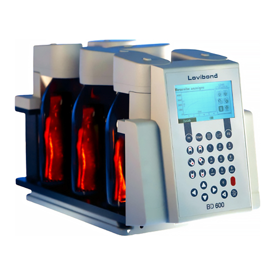
- Page 1 Lovibond Water Testing ® Tintometer Group ® BOD-System BD 600 Instruction Manual www.lovibond.com...
- Page 2 IMPORTANT ! Read this entire manual carefully before use! Carefully read and follow the SAFETY INSTRUCTIONS at the beginning of this manual! The system may only be used by qualified persons! Keep this manual for later reference! Also observe important notices in order to avoid malfunctions and faults. If possible, save the complete transport packaging for later transport.
-
Page 3: Safety Instructions
Safety instructions Follow the safety instructions listed here for your own safety! The safety instructions draw your attention to potential dangers. They also contain information for how you can prevent danger with appropriate conduct. Use is only permitted for qualified persons. DANGER of electric shock! Only handle the mains adapter with dry hands! Protect the mains adapter from moisture... - Page 4 Wear protective gloves! Avoid contact with the eyes and skin! ATTENTION! Only use the supplied mains adapter! If an incorrect mains adapter is used, the EMC protective goals may not be achieved. SAFETY DATA SHEETS: http://www.lovibond.com/support/sicherheitsdatenblatter BD 600_GB_1 08/2015...
-
Page 5: Table Of Contents
Content Important information Disposal The Measurement System Principle of the method ......... 8 Area of application . - Page 6 Determining the BOD Selection of sample volume ........26 Preparation of the water sample.
-
Page 7: Important Information
Important information ATTENTION! The tolerances / measurement precision specified here only apply for use of the devices in EMC en- vironments in compliance with the basic requirements in accordance with DIN EN 61326-1:2013. Only use the supplied mains adapter! Use of an incorrect mains adapter can result in damage to the measurement system and/or the stirrer drive. -
Page 8: Disposal
Disposal Disposal of consumable materials, batteries, and, if applicable, the entire system must take place in accordance with local legal regulations. The Measurement System Principle of the method BOD measurement by means of pressure differential in a closed system (respirometric BOD measure- ment). -
Page 9: Information About The Method
1 x BOD base unit with integrated bottle rack 6 x BOD sensor (material ABS)* 6 x BOD bottles 6 x seal cup 6 x magnetic stir bar 3 x battery, alkali manganese ( C / LR14 ) 1 x retaining tube for batteries 1 x stirrer drive 1 x mains adapter + primary adapter plug... -
Page 10: Sample Preparation / Brief Summary
Sample preparation / brief summary WARNING! Observe the SAFETY INSTRUCTIONS at the beginning of the manual! • Estimate the measurement range of the sample to be tested and the sample volume as indicated in section 6.1. • If necessary, pre-treat the sample as indicated in 6.2 (e.g. adjust pH value, filtrate) •... - Page 11 Figure 2 BD 600_GB_1 08/2015...
-
Page 12: Initial Commissioning
Initial commissioning The device can be supplied with power via the accompanying mains adapter or batteries. If the mains adapter is connected and batteries are inserted, the device is supplied via the mains adapter and the batteries are not used. If the mains adapter is removed during operation, a seamless transition to battery operation takes place automatically. -
Page 13: Switching On And Off
Insert the mains adapter in the socket and connect it to the side of the device. The mains adapter can supply the BD 600 measurement system and the stirring device with power via the supplied Y-adap- ter. -
Page 14: General Menu Information
General menu information The name of the submenu which the device is currently activated is shown to the left in the header. The date and time are displayed to the right. The display format for date and time can be adjusted under ‚Options‘. The display area is reserved for the open menu. -
Page 15: Start Measurement/Measurement Series
5.5.2 Start measurement/measurement series The ‚Start measurement series‘ menu is divided into three areas ‚Measurement position / name‘, ‚Measuring range / sample volume / ATH‘, and ‚Measuring duration / measuring interval‘. You can switch between the three areas with the up ▲... -
Page 16: Display Current Values
5.5.3 Display current values All six measurement positions are displayed with a symbol. The corresponding current value is displayed next to them. If no head is present, the symbol is completely grey and no current value is displayed (Figure 7, Measurement positions 1 to 4). - Page 17 If ‚Underr.‘ appears instead of the measurement value (ab- breviation for underrange, see Figure 9), the recorded mea- surement value is below the starting measurement value. With ‚Overr.‘ (abbreviation for overerrange, see Figure 9), the recorded measurement value is outside the measuring range.
-
Page 18: Export Measurement Series
5.5.5 Export measurement series A schematic diagram of the rack can be shown to the left in the screen. Like in the other menus, the grey symbol (Figure 12, measurement position 6) also means that no head was recognised there by the device. In Figure 12 the heads at measurement positions 1 to 4 are selected. -
Page 19: Options
Options The settings for further submenus, such as ‚Date / time‘ or ‚Name heads‘ are saved in the respective submenu. If the menu is exited with function key F1 (cancel), the old settings take effect again. The new settings are permanently adopted with function key F2 (adopt). -
Page 20: Language
5.6.5 Language The desired language can be set here. The change does not take effect until function key F2 (adopt) is pressed. 5.6.6 Date / Time ATTENTION. Date and time should not be changed before all measurement series have been completed. -
Page 21: Auto-Off
Ensure that both conditions are met and start the update with the right arrow ► key. A security query follows. Confirm this with function key F2 (OK). Now the boot loader which performs the update starts up. The device then restarts. Updates can be found on our website www.lovibond.com under ‚Support‘. BD 600_GB_1 08/2015... -
Page 22: Interfaces
Interfaces Figure 18 1 SD card holder 2 USB host interface NOTE! The USB host interface is only intended for USB sticks. USB hubs, external hard disks, and adapter sticks (e.g. USB SD card adapters) are not supported. Battery operation entails the limitation that the host interface can only provide 200 mA. -
Page 23: Remote Control
Remote control 5.8.1 Preparation The device can also be controlled via remote control. For this purpose, activate the remote control item in the Options menu and assign the two-digit device ID. If multiple devices are used, enter a dif- ferent device ID for each device. This is necessary for the remote control commands to reach a specific device. -
Page 24: Error Messages And Notices
Error messages and notices Message in the display Meaning RTC Error! The message appears when the device is switched on and the RTC Please set the date and time (real-time clock) has forgotten its time. Adjust the time in the follo- again. - Page 25 Updates are only possible in This appears if an update is started from the Options menu and the mains operation. mains adapter is not connected. The update file ‚bod.hex‘ This appears if an update was started from the Options menu and was not found.
-
Page 26: Determining The Bod
Determining the BOD WARNING! Observe the SAFETY INSTRUCTIONS at the beginning of the manual. DANGERS can arise from the sample, the KOH, and the nitrification inhibitor! Selection of sample volume The BOD value of the sample to be expected determines the volume used. A BOD measurement range (without dilution of the sample) from 0 –... - Page 27 This can take place directly in the thermostat cabinet. Alternatively, due to the user-friendly design of the BD 600, it is also possible to remove the entire BOD base unit with the integrated bottle rack from the thermostat cabinet, while the inductive stirring system remains in the cabinet.
-
Page 28: Instructions For Evaluation Of Results
Instructions for evaluation of results Figure 21, typical BOD curve 1. The BOD measurement values must always be higher than on the preceding day. 2. The BOD measurement values do not increase linearly. The increase is always smaller than on the preceding day. -
Page 29: Testing The Measurement System
Testing the measurement system A test kit (Art. no. 2418328) is available for testing the BD 600. The test kit enables the testing of all components. It comprises special reagent tablets which generate a defined vacuum in the closed BOD bottle. -
Page 30: Inductive Stirring System
10 Inductive stirring system 1 Mains adapter 2 DC connection cable 3 Stirrer drive 4 Stirring position 5 Y-cable Figure 22, stirrer drive, mains adapter, Y-cable 10.1 Device description and functional description The inductive stirring system is designed for the stirring of liquids in special BOD bottles. It comprises a super-flate stirrer drive with 6 stirring positions and the mains adapter. -
Page 31: Magnetic Stir Bars
Connect the DC connection cable of the mains adapter with the supplied Y-cable. Insert on of the Y-cable plugs into the power supply socket of the stirrer drive. The second branch of the Y-cable is intended for power supply of the measurement system. Plug the mains adapter into a suitable socket. In order to ensure smooth stirring operation, it may be necessary to adjust the screws on the bottle rack. -
Page 32: Decommissioning
11 Decommissioning Disconnect the external power supply from the unit in order to decommission the system. Disconnect the mains adapter plug from the mains supply. Remove batteries from the measurement system. Remove seal caps from the test bottles and clean in the correct manner. Empty and clean test bottles correctly. -
Page 33: Technical Data
12 Technical data 12.1 BOD Measurement System Type BD 600 Measuring principle Respirometric; electronic pressure sensor Measurement ranges [mg/l O 0 40, 0 80, 0 200, 0 400, 0 800, 0 2000, 0 4000 Applications , BOD , OECD 301 F, etc. -
Page 34: Mains Adapter
12.3 Mains adapter Type SRP1502300P Design Mains adapter plug, switching power supply Input voltage, frequency 100 – 240 V, 50 / 60Hz Input current 1500 mA Primary adapter Europe, UK, Australia, USA Protection class Output voltage, frequency 15 V, DC Max. -
Page 35: Accessories And Spare Parts List
13 Accessories and spare parts list Article Order code Spare BOD sensor 2444470 Mains adapter plug 444454 Inductive stirrer drive, with mains adapter 2444456 Test kit for system testing 2418328 Potassium hydroxide solution, 50 ml 2418634 Nitrificaiton inhibitor B, 50 ml 2418642 BOD bottle 418644... - Page 36 Tintometer GmbH The Tintometer Limited Tintometer AG Tintometer Inc. Lovibond ® Water Testing Lovibond House / Solar Way Hauptstraße 2 6456 Parkland Drive Schleefstraße 8-12 Solstice Park / Amesbury, SP4 7SZ 5212 Hausen AG Sarasota, FL 34243 44287 Dortmund Tel.: +44 (0)1980 664800 Tel.: +41 (0)56/4422829...
Need help?
Do you have a question about the BD 600 and is the answer not in the manual?
Questions and answers