Table of Contents
Advertisement
Quick Links
SETUP & OPERATION MANUAL
FEATURES
Powerful 3 HP motor provides plenty of power to
suit a wide variety of cutting applications.
Variable blade speed - ideal for cutting ferrous
materials.
Mitering capabilities - stops at 90°, 45° left and
45° right.
Heavy-duty spindle and worm gear box.
Quick-clamp vise for easy work piece loading.
Control handle with safety trigger switch.
Coolant pump system with high volume tank.
Specially designed water channel for better
cooling effect.
Shock-proof control panel.
Overload protected inverter.
Digital spindle speed display.
SPECIFICATIONS
• Cutting capacity at 90º
3 3/8" (85 mm)
4 3/4" (120 mm) 3" (75 mm)
4" x 4" (102 x 102 mm)
6 1/8" x 3 1/2" (155 x 90 mm)
• Cutting capacity at 45°
3" (75 mm)
3 3/4" (95 mm)
3 1/8" x 3 1/8" (80 x 80 mm)
3 1/8" x 2 3/4" (80 x 70 mm)
• Blade
14" x 1 1/4" (350 x 32 mm) - optional
• Spindle speed
24 to120 rpm
• Maximum vise opening
6 11/16" (170 mm)
• Coolant pump
1/8 HP
• Coolant tank
5 liters
• Overall dimensions
47 1/4" x 40 1/8" x 76 3/4"
(1200 x 1020 x 1950 mm)
• Stand dimensions
23 5/8" x 22 13/16" x 28 3/8"
(600 x 580 x 720 mm)
• Motor
3 HP , 220 V, 3 Ph, 9.6 A
• Weight
550 lbs (250 kg)
Version
2_Revision
2 - October 2015
#
#
© Copyright General International
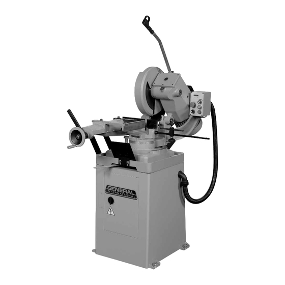
14" COLD CUT SAW
- ELECTRONIC VARIABLE SPEED
MODEL
60-350
#
Advertisement
Table of Contents

Related Manuals for General International 60-350


Summary of Contents for General International 60-350
- Page 1 23 5/8” x 22 13/16” x 28 3/8” (600 x 580 x 720 mm) • Motor 3 HP , 220 V, 3 Ph, 9.6 A 60-350 • Weight 550 lbs (250 kg) Version 2_Revision 2 - October 2015 © Copyright General International...
- Page 2 Telephone (514) 326-1161 • Fax (514) 326-5555 • www.general.ca THANK YOU for choosing this General® International model 60-350 14” variable speed cold cut saw. This cold cut saw has been carefully tested and inspected before shipment and if properly used and maintained, will provide you with years of reliable service.
- Page 3 GENERAL INTERNATIONAL WARRANTY ® All component parts of General International and Excalibur by General International products ® ® are carefully inspected during all stages of production and each unit is thoroughly inspected upon completion of assembly. Limited Lifetime Warranty Because of our commitment to quality and customer satisfaction, General International agrees to ®...
-
Page 4: Table Of Contents
TABLE OF CONTENTS Rules for safe operation ..................... 5 Electrical requirements ...................... 6 Identification of main parts and components ..............7 Unpacking .......................... 8 Basic functions ........................8 Placement within the shop ....................9 Assembly instructions ....................9-14 Installing the downfeed handle ........................9 Installing a blade .............................. -
Page 5: Rules For Safe Operation
RULES FOR SAFE OPERATION To help ensure safe operation, please take a moment to learn the machine’s applications and limitations, as well as potential hazards. General International disclaims any real or implied warranty and hold itself ® harmless for any injury that may result from the improper use of its equipment. 1. -
Page 6: Electrical Requirements
ELECTRICAL REQUIREMENTS BEFORE CONNECTING THE MACHINE TO THE POWER SOURCE, VERIFY THAT THE VOLTAGE OF YOUR POWER SUPPLY CORRESPONDS WITH THE VOLTAGE SPECIFIED ON THE MOTOR I.D. NAMEPLATE. A POWER SOURCE WITH GREATER VOLTAGE THAN NEEDED CAN RESULT IN SERIOUS INJURY TO THE USER AS WELL AS DAMAGE TO THE MACHINE. -
Page 7: Identification Of Main Parts And Components
IDENTIFICATION OF MAIN PARTS AND COMPONENTS LEVELING BOLT (4) ELECTRONIC INVERTER ACCESS DOOR SWIVEL BASE LOCK LEVER VISE HANDLE QUICK LOCK LEVER VISE BLADE GUARD DOWNFEED HANDLE PANEL CONTROL MOTOR WORKPIECE STOP BAR DEPTH STOP MITER SCALE WORKPIECE STOP... -
Page 8: Unpacking
4 MM ALLEN KEY ..............1 BASIC FUNCTIONS This General International model 60-350 14” slow speed cold cut saw is designed for multipurpose cutting applica- tions in all types of metal fabrication shops. With the correct carbide or hi-speed steel blade, the built-in coolant system, and its low rpm blade speed this unit is designed to produce cleaner more accurate cuts, as compared to abrasive wheels, on a variety of materials including, aluminum, steel, brass and other work pieces of various sizes and profiles. -
Page 9: Placement Within The Shop
PLACEMENT WITHIN THE SHOP / SAFETY ZONE THIS COLD CUT SAW MODEL 60-350 IS HEAVY. DO NOT OVER-EXERT. A HOIST OR FORKLIFT WITH STRAPS SHOULD BE USED TO LIFT THIS MACHINE. TO LIMIT THE RISK OF SERIOUS INJURY OR DAMAGE TO THE MACHINE, ANY EQUIPMENT USED TO LIFT THIS MACHINE SHOULD HAVE A RATED CAPACITY IN EXCESS OF 550 LBS (250 KG). -
Page 10: Installing A Blade
Ask your local tool dealer for suggestions for 14” x 1 1/4” (350 X 32 mm) cold cut blades. Please note that General International offers an optional a 14” hi-speed steel general purpose blade (#60-355). - Page 11 BEFORE ASSEMBLING, MAKE SURE THAT THE SWITCH IS IN THE ”OFF” POSITION AND THAT THE POWER CORD IS UNPLUGGED. DO NOT PLUG IN OR TURN ON THE MACHINE UNTIL YOU HAVE COMPLETED THE ASSEMBLY AND INSTALLATION STEPS DESCRIBED IN THIS SECTION OF THE MANUAL. INSTALLING A BLADE (CONTINUED) Remove the blade flange screw using a 10 mm Al- Remove the blade flange from the blade holder.
-
Page 12: Installing The Support Roller
BEFORE ASSEMBLING, MAKE SURE THAT THE SWITCH IS IN THE ”OFF” POSITION AND THAT THE POWER CORD IS UNPLUGGED. DO NOT PLUG IN OR TURN ON THE MACHINE UNTIL YOU HAVE COMPLETED THE ASSEMBLY AND INSTALLATION STEPS DESCRIBED IN THIS SECTION OF THE MANUAL. INSTALLING A BLADE (CONTINUED) 10. -
Page 13: Installing The Work Stop
BEFORE ASSEMBLING, MAKE SURE THAT THE SWITCH IS IN THE ”OFF” POSITION AND THAT THE POWER CORD IS UNPLUGGED. DO NOT PLUG IN OR TURN ON THE MACHINE UNTIL YOU HAVE COMPLETED THE ASSEMBLY AND INSTALLATION STEPS DESCRIBED IN THIS SECTION OF THE MANUAL. INSTALLING THE WORKPIECE STOP Remove the workpiece stop support using a 5 mm Using a rubber mallet, tap gently on the support to... -
Page 14: Installing The Vise Handle
BEFORE ASSEMBLING, MAKE SURE THAT THE SWITCH IS IN THE ”OFF” POSITION AND THAT THE POWER CORD IS UNPLUGGED. DO NOT PLUG IN OR TURN ON THE MACHINE UNTIL YOU HAVE COMPLETED THE ASSEMBLY AND INSTALLATION STEPS DESCRIBED IN THIS SECTION OF THE MANUAL. INSTALLING THE VISE HANDLE Screw the handle into the mounting hole on the Tighten the handle using a 12 mm wrench. -
Page 15: Blade Speed Adjustment
MAKE SURE THE MACHINE HAS BEEN TURNED OFF AND UNPLUGGED FROM THE POWER SOURCE BEFORE PERFORM- ING ANY MAINTENANCE OR ADJUSTMENTS. BLADE SPEED ADJUSTMENT The blade speed ranges from 24 to 120 rpm. The blade speed control knob is located on the control box, just above the on button. -
Page 16: Adjusting The Cut Angle
MAKE SURE THE MACHINE HAS BEEN TURNED OFF AND UNPLUGGED FROM THE POWER SOURCE BEFORE PERFORM- ING ANY MAINTENANCE OR ADJUSTMENTS. ADJUSTING THE CUT ANGLE To unlock the swivel base push lever A to the left as Refer to the graduated scale B at the base of the shown. -
Page 17: Adjusting The Machine Head Stops
MAKE SURE THE MACHINE HAS BEEN TURNED OFF AND UNPLUGGED FROM THE POWER SOURCE BEFORE PERFORM- ING ANY MAINTENANCE OR ADJUSTMENTS. ADJUSTING AND USING THE VISE (CONTINUED) To adjust the vise jaw, loosen screw A with a 10 mm Note: Pull back the vise assembly to allow the rotation of the saw head all way to the right, especially for miter cuts. -
Page 18: Operating Instructions
OPERATING INSTRUCTIONS CHECKLIST BEFORE STARTING VERIFY ALL CHECK POINTS BEFORE STARTING. FAILURE TO COMPLY CAN RESULT IN SERIOUS INJURIES. Make sure you and any assistants are wearing safe and appropriate workshop attire. To reduce the risk of damage to the machine, as well as potential for personal injury, after initial set-up as well as before each use, make sure that everything is securely installed and that all fasteners and moving parts on this machine are locked in place before starting the machine. -
Page 19: Maintenance
MAKE SURE THE MACHINE HAS BEEN TURNED OFF AND UNPLUGGED FROM THE POWER SOURCE BEFORE PERFORM- ING ANY MAINTENANCE OR ADJUSTMENTS. MAINTENANCE CLEANING For optimum performance from your machine follow this maintenance schedule and refer to any specific instruc- tions given in this section. After using your machine, sweep up and discard any excess metal chips and debris. REGULAR MAINTENANCE TASK FREQUENCY DAILY WEEKLY... -
Page 20: Fuse Replacement
MAKE SURE THE MACHINE HAS BEEN TURNED OFF AND UNPLUGGED FROM THE POWER SOURCE BEFORE PERFORM- ING ANY MAINTENANCE OR ADJUSTMENTS. FUSE REPLACEMENT Shut off the power source by turning the lock-out Remove the two front plate screws with a Phillips safety switch counterclockwise. -
Page 21: Parts List & Diagrams
DIAGRAM... - Page 22 PARTS LIST IMPORTANT: When ordering replacement parts, always give the model number, serial number of the machine and part number. Also a brief description of each item and quantity desired. PART # DESCRIPTION SPECIFICATIONS 60350-A01 BASE LOCK LEVER 60350-A02 NYLOCK NUT 60350-A03 CAP SCREW 60350-A04...
- Page 23 PARTS LIST IMPORTANT: When ordering replacement parts, always give the model number, serial number of the machine and part number. Also a brief description of each item and quantity desired. PART # DESCRIPTION SPECIFICATIONS 60350-A55 CAP SCREW 60350-A56 60350-A57 WASHER 60350-A58 LINK PLATE W/THREAD 60350-A59...
- Page 24 PARTS LIST IMPORTANT: When ordering replacement parts, always give the model number, serial number of the machine and part number. Also a brief description of each item and quantity desired. PART # DESCRIPTION SPECIFICATIONS 60350-A109 LOCK KNOB 5 X 55 60350-A110 WORKPIECE STOP BRACKET 60350-A111...
- Page 25 DIAGRAM & PARTS LIST CABINET AND PUMP IMPORTANT: When ordering replacement parts, always give the model number, serial number of the machine and part number. Also a brief description of each item and quantity desired. PART # DESCRIPTION SPECIFICATIONS QTY PART # DESCRIPTION SPECIFICATIONS QTY...
- Page 26 WIRING DIAGRAM...
- Page 27 NOTES...
-
Page 28: Contact Information
8360 Champ-d’Eau, Montreal (Quebec) Canada H1P 1Y3 Tel.: (514) 326-1161 Fax: (514) 326-5565 - Parts & Service / (514) 326-5555 - Order Desk orderdesk@general.ca www.general.ca Follow us:...
Need help?
Do you have a question about the 60-350 and is the answer not in the manual?
Questions and answers