Table of Contents
Advertisement
Quick Links
A Beijer Electronics Group Company
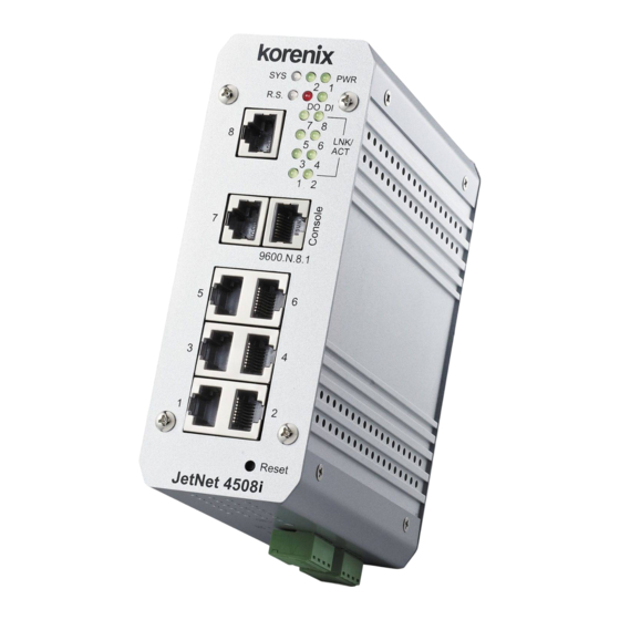
JetNet 4508i/4508if Series Industrial Ethernet Managed Switch
Quick Installation Guide V1.0
Overview
The JetNet 4508i/JetNet 4508if are new generation industrial managed Fast Ethernet Switch
with advanced layer-2 management features and isolated system design for the power
distribution or power feeding application.
The JetNet 4508i/4508if series offer 6-port Fast Ethernet RJ-45 connectors plus 2-port Fast
Ethernet Fiber interfaces – JetNet 4508if, or 8-port Fast Ethernet RJ-45 connectors – JetNet
4508i. Both of models adopted 32Gbps High performance Ethernet Switch Fabric to ensure
real-time and high quality connectivity in various networking application, and the isolated
system design fulfilled a very high level EMC inquire for the Substation application and
compliance with IEC 61850-3 and IEEE 1613 as well. The Switches also supports IP31
enclosure protection and 2 operating temperature models- normal temperature for general
purpose -25~70°C (JetNet4508i), -10~70°C (JetNet 4508if ) and wide operating temperature
for rugged environment -40~75°C (JetNet 4508i-w/ JetNet 4508if-w).
This quick installation guide introduces the system powering, device installation and how to
connect the Ethernet interface. For more switch configuration, please download the JetNet
4508 series user manual from Korenix Website.
Package Check List
A Beijer Electronics Group Company
JetNet 4508i or JetNet 4508if
JetNet 4508i/4508if Series Industrial Ethernet Managed Switch
Quick Installation Guide V1.0
Overview
The JetNet 4508i/JetNet 4508if are new generation industrial managed Fast Ethernet Switch
with advanced layer-2 management features and isolated system design for the power
with DIN Rail kit x1
distribution or power feeding application.
The JetNet 4508i/4508if series offer 6-port Fast Ethernet RJ-45 connectors plus 2-port Fast
Ethernet Fiber interfaces – JetNet 4508if, or 8-port Fast Ethernet RJ-45 connectors – JetNet
4508i. Both of models adopted 32Gbps High performance Ethernet Switch Fabric to ensure
real-time and high quality connectivity in various networking application, and the isolated
system design fulfilled a very high level EMC inquire for the Substation application and
compliance with IEC 61850-3 and IEEE 1613 as well. The Switches also supports IP31
Quick Installation Guide
enclosure protection and 2 operating temperature models- normal temperature for general
purpose -25~70°C (JetNet4508i), -10~70°C (JetNet 4508if ) and wide operating temperature
for rugged environment -40~75°C (JetNet 4508i-w/ JetNet 4508if-w).
This quick installation guide introduces the system powering, device installation and how to
connect the Ethernet interface. For more switch configuration, please download the JetNet
4508 series user manual from Korenix Website.
Console Cable (RJ-45 /DB9)
Installation
Mount the unit
Din-Rail mount: Mount the din-rail clip on the rear of JetNet
4508i/4508if on the DIN rail. For information about the DIN Rail
installation, please refer to user's manual.
Grounding JetNet Switch
There is one grounding screw on the bottom
side of JetNet 4508i/4508if. Connect the frame
grounding of JetNet 4508i/4508if to the
grounding surface to ensure safety and prevent
noise to interfere communication.
Wiring the Power Inputs
1. Insert the positive and
negative wires into the V+ and V-
contact on the terminal block
connector.
2. Tighten the wire-clamp screws to prevent the power wires from being loosened.
Notes: The recommended typical operating voltage is DC 24V (Input range: DC12~ 36
V), maximum power consumption is 15 Watts.
Wiring the Relay Output (DO)
The relay output contacts are in
the bottom side as shown on
Figure-3. The relay output (DO)
is controlled by the pre-defined
operating rules. To activate relay
output function, please refer to
the User's Manual for the Relay
Figure-3
Output information.
Note: The relay contactors only supports 1A current, DC 24V. It is not recommended to
apply voltage and current higher than the specifications.
Wiring the Digital Input (DI)
The Digital Input (D.I.) contacts
are in the bottom side of the
device as shown in Figure-4.
It accepts one external DC type
signal
input
and
can
be
configured to send alert message
through Ethernet when the signal
Figure-4
is changed.
Note: the DI accepts DC type signal and supports isolated input circuit with Digital
High Level input DC 11V~30V and Digital Low Level input DC 0V~10V. Do not apply
voltage higher than the specification; it may cause internal circuit damage or a wrong
action of DI.
Connecting to Network
1. Connecting the Ethernet Port: Connect the Ethernet port of JetNet 4508i/JetNet 4508if
series with the other Ethernet device by Cat-5/Cat-6 UTP or STP cable, and then the
LNK/ACT LED will turn on and start flashing to indicate the communication is occurred
between 2 devices.
2. Connecting the Fiber Port: Cross-connect the transmit channel at each end to the receive
channel at the opposite end as illustrated in the Figure-5 (JetNet 4508if series).
ATTENTION
This is a Class 1 Laser/LED product.
Don't look into the Laser/LED Beam.
A
Device Management
JetNet 4508i/JetNet 4508if series provide both in-band and out-band configuration methods,
and adopted same software as JetNet 4508/4508f series. You can configure the switch via the
RS-232 console with the attached console cable or you can remotely manage the switch via
network. You can choose Telnet/SSH, Web/HTTPS management.
1. Preparation for console management: Attach the RS-232 DB9 connector to your PC's
COM port. Connect the RJ-45 connector to the console port of the JetNet 4508i/4508if
Switch.
Go to Start -> Program -> Accessories -> Communication -> Hyper Terminal
Give a name to the new console connection.
Choose the COM name and select the correct serial settings. The serial port settings of
JetNet 4508 are as below: 9600bps, No parity check, 8 Data bits, 1 stop bit
After connected, you will see the Switch login request. Type the username and password and
then you can login. The default username is "admin", password is "admin".
Follow the manual to configure the software features.
2. Preparation for Web management: Before you attempt to use the embedded web
interface to manage switch operation, verify that JetNet 4508i/4508if is properly installed
on your network and that every PC on this network can access the switch via the web
browser.
Type http://4508_IP_Address (The default IP address is
192.168.10.1.), then press Enter.
The login screen will appear next.
Type in the user name and password and click "OK"
button. The welcome page of the Web-Based management
interface will appear then. The default user name and
password is admin/admin.
At the left column of the web
management interface are the software
features, where ring column will list the
available settings.
For more operating instructions, please
refer to the User's manual of JetNet 4508i/JetNet 4508if V2 series included in the packing
or downloadable from the Korenix Website – www.korenix.com.
Support
5 Years Warranty
Each of Korenix's product line is designed, produced, and tested with high industrial
standard. Korenix warrants that the Product(s) shall be free from defects in materials and
workmanship for a period of five (5) years from the date of delivery provided that the
Product was properly installed and used.
This warranty is voided if defects, malfunctions or failures of the warranted Product are
caused by damage resulting from force measure (such as floods, fire, etc.), other external
forces such as power disturbances, over spec power input, or incorrect cabling; or the
warranted Product is misused, abused, or operated, altered and repaired in an unauthorized
or improper way.
TX
TX
Attention! To avoid system damage caused by sparks, please DO NOT plug in power
connector when power is on.
The product is in compliance with Directive 2002/95/EC and 2011/65/EU of the European
RX
RX
B
Parliament and of the Council of 27 January 2003 on the restriction of the use of certain
hazardous substances in electrical and electronics equipment(RoHS Directives & RoHS 2.0)
Korenix Customer Service
KoreCARE is Korenix Technology's global service center, where our professional staffs are
ready to solve your problems at any time Korenix global service center's e-mail is
KoreCARE@korenix.com.
For more information and documents download please visit our website:
http://www.korenix.com/downloads.htm
Advertisement
Table of Contents

Related Manuals for Korenix JetNet 4508i Series


Summary of Contents for Korenix JetNet 4508i Series
- Page 1 4508 series user manual from Korenix Website. Connecting to Network standard. Korenix warrants that the Product(s) shall be free from defects in materials and Console Cable (RJ-45 /DB9) workmanship for a period of five (5) years from the date of delivery provided that the 1.
- Page 2 -40~75°C (JetNet 4508i-w/ JetNet 4508if-w). This quick installation guide introduces the system powering, device installation and how to connect the Ethernet interface. For more switch configuration, please download the JetNet 4508 series user manual from Korenix Website. (RJ-45 /DB9) Figure-4...
Need help?
Do you have a question about the JetNet 4508i Series and is the answer not in the manual?
Questions and answers