
Related Manuals for Icegame Bean Bag Toss


Summary of Contents for Icegame Bean Bag Toss
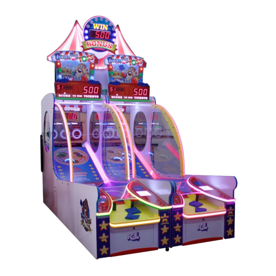
- Page 1 Service Manual Innovative Concepts in Entertainment 10123 Main Street Clarence, New York 14031...
- Page 2 Table of Contents Safety and Warnings Before you Begin Game Assembly Unbox and install the conveyor belt Cabinet Assembly Mega Marquee Setup How to program Program Options Suggestive Ticket Settings Error Codes & Solutions 20 - 28 Fast Access to the Sensors Access to the playfield 30 - 31 Stir Stick Update...
- Page 3 SAFETY AND WARNINGS BEFORE YOU BEGIN WARNING: WHEN INSTALLING THIS GAME, A GROUNDED A.C. RECEPTACLE MUST BE USED. FAILURE TO DO SO COULD RESULT IN INJURY TO YOURSELF OR OTHERS. FAILURE TO USE A GROUNDED RECEPTACLE COULD ALSO CAUSE IMPROPER GAME OPERATION, OR DAMAGE TO THE ELECTRONICS. NOTE: THIS GAME IS INTENDED FOR INDOOR USE ONLY.
- Page 4 Components Included with your Game and Needed for Assembly. Note: Game might ship assembled. FOUND ON TOP OF GAME WRAPPED FOUND IN BOX FOUND ON TOP OF GAME WRAPPED BEAN BAGS QTY 20 12 = GAME 8 = SPARE Found in a box inside the game.
- Page 5 Unbox and INSTALL THE BELT A) Install the belt by tilting the motor under the front control panel. B) Push the Belt Assembly forward C) Secure the belt assembly with PC60622 bolts with washers in 8 places. Then add the AA655 in 4 places. (this will secure the metal frame to the wood cabi- net.) Adjust the metal plate (if needed) the metal plate...
- Page 6 Step 1: Remove both the back panel at the top and bottom of the back section of the cabinet. Note: Wood panel version is shown. AA6281 + AA6212 = Wood PC60622 + AA6212 = ABS Plastic Unlock the lower panel...
- Page 7 Step 2: Parts A + B + C + D. READ ALL PARTS BEFORE PROCEEDING! (A) With the cabinet still separated, attach the two harnesses located near the floor. Attach both the AC and front harness extensions together. ** WARNING ** Pay attention to the conveyor and playfield assemblies when sliding the two cabinets together.
- Page 8 ** WARNING ** (C) The cabinets must be equally leveled before sliding together!! (D) The playfield cannot touch the conveyor belt when cabinets are flush. There must be a gap of 1/8 to 1/4 inch between the belt and playfield assembly. Serious damage to the belt will occur if touching. To adjust the gap, loosen the two Hex bolts shown below, pull the playfield assembly slightly back un- til the desired gap is made.
- Page 9 Step 3: Latch the two cabinets together using the provided latch tool. Step 4: Attach the left playfield shield by Inserting AA6220 bolts and AA6212 washers through the outside of the cabinet.
- Page 10 Step 5: From the inside attach AA6212 washers and AA6966 nylon nuts but do not tighten now. Step 6: If installed, remove the conveyor finger shield and put aside. Four bolts secure the finger shield. If your unit is packaged with a finger shield removed, then you will install this after step 8.
- Page 11 Step 7: Plug the RGB LED harness in and re-install cover. Do not reinstall the finger guard cover until both sides glass panels are installed. Slide the TL3213 LED cover on the left side and T3212 led cover on the right side.
- Page 12 Step 9: Repeat steps 4 through 7 for the right side . Step 10: Slide the front playfield shield with the curved side toward the front of the cabinet.
- Page 13 Step 11: Secure the plastic by inserting a TL3243 into the top slot and use AA6210 hat nut outside and AA6211 on the inside. Some units will have two plastic locks per side for a total of four TL3243’s holding the front shield. Step 12: Lift the small marquee up onto the game.
- Page 14 Step 13: Secure the small marquee with four AA6281 and AA6212, two on each side. Put 12 bean bags ONLY into the game. Do not use more or less!! If you don’t have a Mega Marquee, proceed to programming. 12 ONLY...
- Page 15 Components Included with your Mega Marquee. X’s 9 AA6019 TL3216B TL3216A Step 1: Mega Marquee Install Attach the two piece 1/2 spacer using five AA6019 wood screws at the front and four across the top. ONLY ONE SIDE SHOULD A SPACER BE INSTALLED...
- Page 16 Step 2: Position two games together as shown Step 3: Note the position of the indicated holes. These will be used to mount the mega marquee.
- Page 17 Step 4: Lift the marquee up onto the game. Secure it using four AA6281 Allen bolts and four AA6212 washers. Connect one of the games to the marquee sign using provided link cable. Plug AC power cord and made sure switch is set to the on position (I, not O).
- Page 18 Programming Options for Tail Gate Toss Software Revision 2.06 Option Default Game Volume Game Volume. Music Volume Music Volume. Coin 1 Cost of Game. # of Coin 1 pulse’s. Discount # of Games till Disc. Games Per Credit # of Games Added per Credit. Game Time Game in Seconds.
- Page 19 (8-32 x 1”) screws. NOTE: To print a Custom Score Chart please contact ICE technical support at (716) 759-0360 Monday through Friday 8:30am to 6:00pm Eastern Standard Time or at www.icegame.com. The values used must be within the software’s maximum and minimum limits.
- Page 20 ERROR CODES When AC power is applied, some devices will do a self-test. The following error codes can be displayed: Error 1 Compact Flash Error Error 2 Wheel Blue Sensor Error on Error 3 Wheel Green Sensor Error on Error 4 Wheel Red Sensor Error on Error 5 Wheel Blue Sensor Error off...
- Page 21 Step 4: First examine the pins both at both boards and at the slip ring. Found bad pins? If yes, repair/replace, reconnect all connectors and retest game. If no, continue. Step 5: Leave the harness unplugged and unplug J9 from the Rotate I/O board (TL2035X). Measure the resistance of the wires going through the slip ring.
- Page 22 Playfield Movement (No error code will be generated at startup): The Playfield motor is turned on through a relay and its direction of rotation is also controlled by the same relay. The motor is turned on by sending a ground signal from main board at J15, pin 2 to the relay J1 connector, at pin 2.
- Page 23 Step by Step to resolve Playfield Movement Issues: No Movement: Step 1: Use a voltage meter and measure between pin 1 of J1 on the relay board and ground on the either power supply. Is +15 VDC present at pin 1? Yes, continue.
- Page 24 Resolving conveyor problems The conveyor motor is powered with 110/230 volts of AC power. AC is provided to the motor when the solid state relay activates. The relay controls the “hot” line of AC to the motor while neutral is connected directly to the motor. The relay is turned on by the main board (TL2034X) by Q5 (Tip 122).
- Page 25 Resolving errors 2 through 7. There are three score holes which are colored red, green, and blue. In each of these holes are two sensors that detect when a bean bag has fallen into the hole. These sensors are enabled by two enable lines. When the game is powered on it will enable only one enable line for the score sensors.
- Page 26 Resolving Error 10. Located at the back of the game is the miss sensor. This sensor is slightly different than the score hole sensors but function the same. When this sensor fails, it will generate error 10 when the game is powered on. A small LED diode located on the sensor board indicates the status of sensor.
- Page 27 How to test Tip122 and IRL 540 transistors in and out of circuit. For the most part, when these components fail, they will short. Although it is best to remove the component in question to do these tests it can be done in circuit and without removing them. Use a multi-meter set it to diode test/check.
- Page 28 How to test Tip122 and IRL 540 transistors in and out of circuit. This test is quick and simply. Using a multi-meter set to diode check, insert the black probe to J21, pin 6. Using the red probe, touch each transistor’s (either a Tip 122 or IRL540) metal tab. The meter should show open.
- Page 29 Easy Access to Sensors: Remove the back cover, and locate the Rotate I/O harness connectors shown below and unplug.
- Page 30 Accessing Playfield Sensors and the Rotate I/O board. Remove the Upper Back Door There are 6 Allen bolts and washers holding the upper back door assembly together. Remove the hardware and put the back door aside. Release the Playfield Drawer There are 2 Allen bolts and washers holding the play- field to the cabinet.
- Page 31 Unplug the LED harnesses Disconnect the LED harnesses on each side. The playfield can now slide out.
- Page 32 SENSOR HOLE STIR STICK STIR STICK SENSOR HOLE...
- Page 33 STIR STICK GREEN HOLE BLUE HOLE IMPORTANT: STIR STICK FLAT END OF THE STIR STICK SHOULD BUTT- FLUSH TO THE EDGE OF THE BLACK PLASTIC. ONCE IN PLACE, DRILL 1/8” PILOT HOLES AND THEN USE SCREWS. GREEN HOLE BLUE HOLE SENSOR HOLE SENSOR HOLE STIR STICK...
- Page 34 TL3030X Assembly TL3035X Assembly...
- Page 35 TL3036X Assembly TL3037X Assembly...
- Page 36 TL3081X Assembly...
- Page 37 TL3090X Assembly...
- Page 39 TL1200X BEAN BAG TOSS GAME Item number Description Item number Description TL2037X Front I/O E00724TLAX ASY (LED STRIP LARGE RGB 24 CUTS TL2007X ASY (POWER MOD 6 AMP) E00724TLCX ASY (LED STRIP LARGE RGB 26 CUTS TL2032X PCBA TIME E00724TLGX...
- Page 40 TL3222X ASY (MARQUEE) Item number Description AA0219 T MOLDING (3/4 BRIGHT GREEN) BL1054X ASY (BALL GATE BRACKET/ARM/ PW2006LB TURQUOISE FUNLIGHT BULB ASY PW2006LG GREEN FUNLIGHT BULB ASY PW2006R RED FUNLIGHT BULB ASSY More Mechanical: • TL1051 (PLAYFIELD BEARING) • WK1050 (PLAYFIELD BEARING) •...
- Page 41 (including labor) that is performed by such a distributor. Innovative Concepts in Entertainment 10123 Main St. Clarence, NY 14031 Phone #: (716) - 759 – 0360 Fax #: (716) – 759 – 0884 www.icegame.com...
Need help?
Do you have a question about the Bean Bag Toss and is the answer not in the manual?
Questions and answers