
Related Manuals for Icegame AF1000X


Summary of Contents for Icegame AF1000X
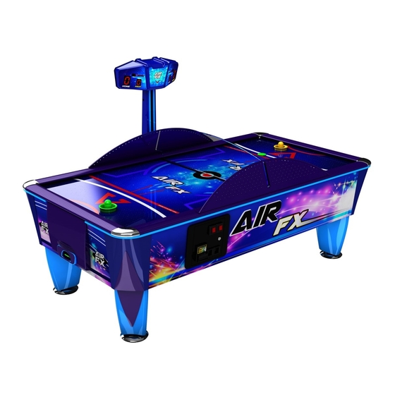
- Page 1 ICE AIR FX AF1000X User Manual Innovative Concepts In Entertainment 10123 Main street, Clarence, NY 14031 WWW.ICEGAME.COM (716) 759-0360 Monday through Friday 8:30am to 6:00pm Eastern Standard...
- Page 2 Table of Contents Assembly Main Board Layout RGB Driver Board Layout Programming 10-12 Deflector Layout Score Display Settings Parts 15-17 Warranty Rev C 10/14/2015...
- Page 3 Locate keys and Open The keys are either located in the coin return of the coin door or screwed to the bottom of the cabinet. There should be two different types of keys. One set for the coin door and another to open the player’s puck doors. Coin Door Locate the legs and feet.
-
Page 4: Assembly
Leg Assembly: After removing the legs from the cabinet, remove the bolt using a 6mm Allen wrench on each leg. You will have to also use a wrench to hold the adjustment rod from spinning out. Then place one feet per leg and reattach the 6mm bolt. - Page 5 Positioning the Table Flip the table onto its legs using at least four people on either side. Opening The cabinet Top: Located in the cash box is the Allen wrench key to open the cabinet top playfield. Insert the wrench as shown and turn counter-clock-wise to unlock the playfield.
-
Page 6: Assembly
Locating the Score Head and sides: The score head assembly is bolted to the bottom of the cabinet. The side rails and divider are attached with straps stapled to the bottom of the cabinet. Installing Score Head: The score head is mounted on the opposite side of the coin door. Insert the wire harness from the score header marquee into the cabinet. - Page 7 Attaching Side Guards: Using four AA6032 8x1/2 Hex w/tek screws attach the side guards. Slide the playfield divider into the side guard slot. Slide the other side guard into the other end of the playfield divider and attach using AA6032 8x1/2 Hex w/tek screws...
- Page 8 Rev B board layout 8 8 8 8 Total FUSE 2 100 volts Enter 230 Volts Down CN10 120 volts CN21 FUSE 1 VOLUME CONTROL CN23 CN19 CN22 CN15 CN11 CN13 CN24 CN19 right speaker + red/white +9 VDC pink right speaker - brown/white ground...
- Page 9 AR2035X RGB Driver Board J1: Connector J2: Connector Color wire Description Color wire Description Orange +12 volts Orange +12 volts Yellow/red Red RGB LED Yellow/red Red RGB LED Yellow/green Green RGB LED Yellow/green Green RGB LED Yellow/blue Blue RGB LED Yellow/blue Blue RGB LED Orange/black...
- Page 10 Ticket PCB CN4: Connector ; Ticket dispensers CN1: Connector ; Power Color wire Description Color wire Description Orange +12 VDC Green w/yellow Earth ground Black Ground No connection Violet/white Ticket run line ; Goes High when tickets are owed. Blue Neutral AC Violet/blue Notch Line ;...
-
Page 11: Programming
Programming: To access configuration menu the machine should have no credits and be at attract mode. To enter the Program Menu press and hold <ENTER> for a few seconds. The display will show “P1”. This informs you that you are in program mode. To navigate the menu: Momentarily pressing the <ENTER>... - Page 12 P1 (goals): Maximum number of goals per game: o Minimum value 2. o Maximum value 9. P2 (time): Maximum length of the game (in minutes): o Minimum value 2. o Maximum value 9. P3 (free games): Length of the free games mode (in hours). o Minimum value 1.
- Page 13 T3: When tickets per goal are delivered. o Minimum value 1 (when goal is scored). o Maximum value 2 (at the end of the game). T4: Number of tickets per won game. o Minimum value 0. o Maximum value 9. T5: Display tickets counter in collection sequence (only if T1=2).
- Page 14 Ball Deflector Mounting Positions ** NOTE ** Color has been changed to red to accent. SA0185W LONG Tone Bar SABOLTKITNEW SA0186W SHORT Tone Bar...
- Page 15 Accessing the SA1228 Boards Step 1: Remove the back cover. Step 2: Remove the standoffs that hold the boards . SA12228 Mounting position determines dipswitch settings. Display SA12230 SA12230...
- Page 16 AR2035X LED Board GF2010 Power supply SA12226A PCB Main AF2007X Power Module WS1022 TICKETBIN (Option) SA6669W Side Protector SA5945W Goal Door assembly SA201605104906 Leg Purple SA11149 AF5001 Leg Leveler Coin Door...
- Page 17 SA6689W SA6689W SA10170 Side Rail Side Rail Corner SA6688W End Rail AF7003 Playfield...
-
Page 18: Parts
SA204200000200 Playfield Motor AF7002 End Decal AF7000 Side Decal Spare Parts List ICE part Description SA0259 Bright Yellow (hard/fast) puck SA1006RF Player handle red SA1007BF Player handle blue E00724AFAX LED strip RGB 59 cuts E00724AFBX LED strip dual 4 cuts E00852AFX LED strip large white 19 cuts AA5014... -
Page 19: Parts
ICE Inc. We cannot be responsible for the quality, suitability or safety of any non-ICE part, modification (including labor) that is performed by such a distributor. Innovative Concepts in Entertainment 10123 Main St. Clarence, NY 14031 Phone #: (716) - 759 – 0360 Fax #: (716) – 759 – 0884 www.icegame.com...
Need help?
Do you have a question about the AF1000X and is the answer not in the manual?
Questions and answers