Table of Contents
Advertisement
Quick Links
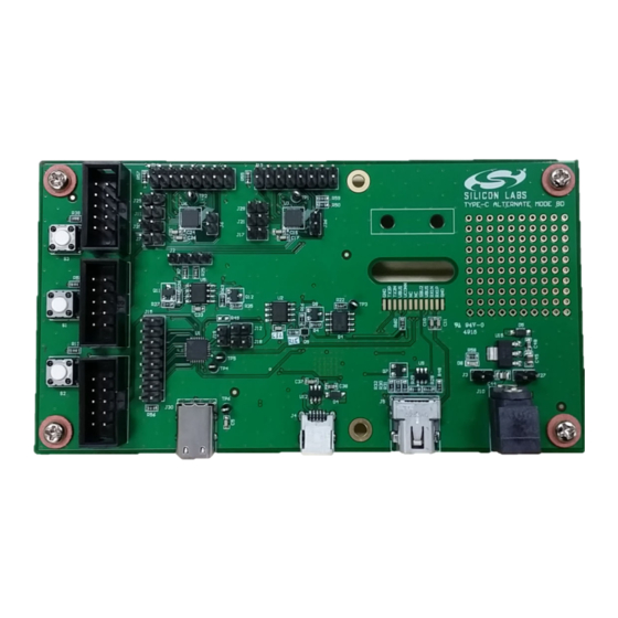
UG233: USB Type-C Reference Design
User's Guide
The EFM8 USB Type-C Reference Design is intended to aid the
development of various USB Type-C applications and consists of
a development board, Simplicity Studio libraries, and example
code.
The board contains Power Delivery (PD) controllers, Billboard devices, and Alternate
Mode functionality.
silabs.com | Smart. Connected. Energy-friendly.
KEY POINTS
• Describes the Type-C reference design
board
• Explains how to load the software
examples and begin evaluation and
development
• Discusses the power scenarios/options
related to the reference board
• Shows how to configure the Debug Serial
Terminal
• Shows the reference design board
schematics
Rev. 0.2
Advertisement
Table of Contents

Related Manuals for Silicon Laboratories UG233


Summary of Contents for Silicon Laboratories UG233
- Page 1 UG233: USB Type-C Reference Design User's Guide The EFM8 USB Type-C Reference Design is intended to aid the KEY POINTS development of various USB Type-C applications and consists of a development board, Simplicity Studio libraries, and example • Describes the Type-C reference design board code.
-
Page 2: Introduction And Running The Demo
UG233: USB Type-C Reference Design User's Guide Introduction and Running the Demo 1. Introduction and Running the Demo The USB Type-C Reference Design is intended to aid the development of various USB Type-C applications and consists of a develop- ment board, Simplicity Studio libraries, and example code. Out of the box, the board is configured as a DisplayPort alternate mode video adapter. -
Page 3: Board Description
UG233: USB Type-C Reference Design User's Guide Board Description 2. Board Description The Type-C reference design board is a platform for developing and evaluating hub and dongle Type-C solutions. The board contains Power Delivery (PD) controllers, Billboard devices, and Alternate Mode functionality. The PD Controller is implemented with EFM8 Busy Bee 3 (EFM8BB3) MCU, and takes advantage of the feature-rich peripherals available on-chip. - Page 4 UG233: USB Type-C Reference Design User's Guide Board Description Figure 2.1. Board Layout Table 2.1. Board Component Map Component Name Function Jumper Must be closed for proper operation. Jumper Alternate Mode PD controller MCU power supply monitoring jumper. Must be closed for normal operation.
- Page 5 UG233: USB Type-C Reference Design User's Guide Board Description The following block diagram can be used to understand the main functions of the reference design and the connections between devi- ces and plugs. Figure 2.2. Functional Block Diagram Overview silabs.com | Smart. Connected. Energy-friendly.
-
Page 6: Evaluation And Development
UG233: USB Type-C Reference Design User's Guide Evaluation and Development 3. Evaluation and Development The Type-C reference design with all of the above-mentioned capabilities is available for free once a Software License Agreement has been signed. After getting the demo to run, the next step is to load the software examples and source code to begin development. - Page 7 UG233: USB Type-C Reference Design User's Guide Power 4. Power For developers’ convenience, the reference board supports a flexible powering scheme, as depicted in the following diagram: Figure 4.1. Power Block Diagram Various power sources can co-exist due to the presence of separate diodes. Below are some power scenarios: 1.
-
Page 8: Debug Serial Terminal Configuration
UG233: USB Type-C Reference Design User's Guide Debug Serial Terminal Configuration 5. Debug Serial Terminal Configuration 1. Install the appropriate CP2108 (USB to Quad UART Bridge Controller) driver for your OS. 2. When connecting the development board for the first time, it may take a while until the USB host enumerates the device. Check the driver installation message and/or the Device Manager for completion. - Page 9 UG233: USB Type-C Reference Design User's Guide Schematics 6. Schematics The schematics for the reference design board are shown below. These are also available within the reference design folder. Figure 6.1. Alternate Mode UFP silabs.com | Smart. Connected. Energy-friendly. Rev. 0.2 | 8...
- Page 10 UG233: USB Type-C Reference Design User's Guide Schematics Figure 6.2. USB Type-C Charging Port silabs.com | Smart. Connected. Energy-friendly. Rev. 0.2 | 9...
- Page 11 UG233: USB Type-C Reference Design User's Guide Schematics Figure 6.3. Billboard Device silabs.com | Smart. Connected. Energy-friendly. Rev. 0.2 | 10...
- Page 12 UG233: USB Type-C Reference Design User's Guide Schematics Figure 6.4. USB to UART Bridge silabs.com | Smart. Connected. Energy-friendly. Rev. 0.2 | 11...
-
Page 13: Simplicity Studio
The products are not designed or authorized to be used within any Life Support System without the specific written consent of Silicon Laboratories. A "Life Support System" is any product or system intended to support or sustain life and/or health, which, if it fails, can be reasonably expected to result in significant personal injury or death.
Need help?
Do you have a question about the UG233 and is the answer not in the manual?
Questions and answers