Table of Contents
Advertisement
Quick Links
UG524: xG24 Dev Kit User's Guide
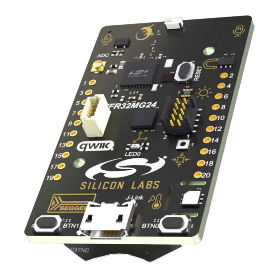
The xG24 Dev Kit is a low-cost, small form factor development
and evaluation platform for the EFR32MG24 Wireless Gecko Sys-
tem-on-Chip.
The board is a small and cost-effective, feature-rich, prototype and development platform
based on the EFR32™ Wireless Gecko System-on-Chip. The xG24 Dev Kit is an ideal
platform for developing energy-friendly connected IoT devices.
The xG24 Dev Kit ships with a Bluetooth demo that works with a cloud-connected smart-
phone app, showcasing easy collection of environmental and motion sensor data.
A built-in SEGGER J-Link debugger ensures easy debugging through the USB Micro-B
connector.
silabs.com | Building a more connected world.
Copyright © 2022 by Silicon Laboratories
TARGET DEVICE
• EFR32 Wireless Gecko System-on-Chip
(EFR32MG24B310F1536IM48-B)
• High-performance 2.4 GHz radio
• 32-bit ARM® Cortex®-M33 with 78.0 MHz
maximum operating frequency
• 1536 flash and 256 kB RAM
KIT FEATURES
• 2.4 GHz ceramic chip antenna
• Power control of on-board peripherals for
ultra-low power operation
• Relative humidity and temperature sensor
• Ambient light sensor
• Hall effect sensor
• 6-axis inertial sensor
• MEMS stereo microphones
• Pressure sensor
• 32 Mbit flash for OTA programming and
data logging
• RGB LED and two push buttons
• Precise voltage reference and dedicated
U.FL connector for ADC measurements
• 20-pin 2.54 mm breakout pads
• Qwiic® connector
• SEGGER J-Link on-board debugger
• Virtual COM port
• Packet Trace Interface (PTI)
• Mini Simplicity connector for AEM and
packet trace using external Silicon Labs
debugger
• USB or coin cell battery powered
• External battery connector
SOFTWARE SUPPORT
• Simplicity Studio™
Rev. 0.1
Advertisement
Table of Contents


Need help?
Do you have a question about the UG524 and is the answer not in the manual?
Questions and answers