Table of Contents
Advertisement
Quick Links
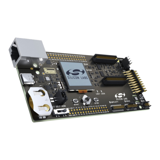
UG573: Si-MB4002A Wireless Pro Kit
Mainboard User's Guide
The Silicon Labs Pro Kit Mainboard is a carrier board for Silicon
Labs radio boards.
The mainboard provides all necessary tools for application development and debugging
of both the attached radio board as well as external hardware. Its features include an on-
board J-Link debugger, Packet Trace Interface (PTI) support, and a Virtual COM port.
The embedded Advanced Energy Monitor (AEM) can accurately measure the radio
board current consumption from 0.1 µA to 495 mA with a time resolution of 100 kSps. All
of these features can be accessed either through USB or Ethernet. The mainboard also
contains sensors and UI peripherals for easy demonstration of some of the capabilities of
an attached radio board.
silabs.com | Building a more connected world.
Copyright © 2024 by Silicon Laboratories
MAINBOARD FEATURES
• Advanced Energy Monitor
• Packet Trace Interface
• Logic analyzer
• Virtual COM Port
• SEGGER J-Link on-board debugger
• External device debugging
• Ethernet and USB connectivity
• Silicon Labs Si7021 Relative Humidity and
Temperature sensor
• Low-power 128x128 pixel Memory LCD
• User LEDs / Pushbuttons
• Joystick
• 20-pin 2.54 mm EXP header
• Breakout pads for radio board I/O
• CR2032 coin cell battery support
SOFTWARE SUPPORT
• Simplicity Studio
• Energy Profiler
• Network Analyzer
ORDERING INFORMATION
• Si-MB4002A
Rev. 1.0
Advertisement
Table of Contents

Related Manuals for Silicon Laboratories UG573


Summary of Contents for Silicon Laboratories UG573
- Page 1 UG573: Si-MB4002A Wireless Pro Kit Mainboard User's Guide The Silicon Labs Pro Kit Mainboard is a carrier board for Silicon Labs radio boards. MAINBOARD FEATURES • Advanced Energy Monitor The mainboard provides all necessary tools for application development and debugging •...
-
Page 2: Table Of Contents
Table of Contents 1. Introduction ....... . 4 1.1 Ordering Information ......4 1.2 Getting Started . - Page 3 6.3.2 Host-to-Target......23 6.3.3 Limitations ......23 6.3.4 Troubleshooting .
-
Page 4: Introduction
UG573: Si-MB4002A Wireless Pro Kit Mainboard User's Guide Introduction 1. Introduction The Pro Kit Mainboard is a carrier board for all Silicon Labs radio boards, featuring several tools for easy evaluation and development of wireless applications. An on-board J-Link debugger enables programming and debugging on the target device over USB or Ethernet. -
Page 5: Hardware Overview
UG573: Si-MB4002A Wireless Pro Kit Mainboard User's Guide Hardware Overview 2. Hardware Overview 2.1 Hardware Layout The layout of the Wireless Pro Kit Mainboard is shown below. Radio Board Breakout Pads Ultra-low power 128x128 pixel Radio Board Socket memory LCD... -
Page 6: Block Diagram
UG573: Si-MB4002A Wireless Pro Kit Mainboard User's Guide Hardware Overview 2.2 Block Diagram A block diagram of the Wireless Pro Kit is shown in the figure below. RJ-45 Ethernet Board Connector Controller Connector Simplicity UART Multiplexer Connector Logic Debug Packet Trace... -
Page 7: Connectors
UG573: Si-MB4002A Wireless Pro Kit Mainboard User's Guide Connectors 3. Connectors This chapter gives you an overview of the Wireless Pro Kit Mainboard connectivity. The placement of the connectors is shown in the figure below. EXP Header P101 (P0 - P14) -
Page 8: Breakout Pads
UG573: Si-MB4002A Wireless Pro Kit Mainboard User's Guide Connectors 3.3 Breakout Pads Most of the radio board pins are routed from the radio board to breakout pads at the top and bottom edges of the Wireless Pro Kit Mainboard. A 2.54 mm pitch pin header can be soldered on for easy access to the pins. The figure below shows you how the pins of the radio board map to the pin numbers printed on the breakout pads. -
Page 9: Exp Header
UG573: Si-MB4002A Wireless Pro Kit Mainboard User's Guide Connectors 3.4 EXP Header The EXP header is an angled, 20-pin header that allows connection of peripherals or plugin boards to the kit. It is located on the right- hand side of the mainboard and contains several I/O pins that can be used with most of the radio board's features. Additionally, the VMCU, 3V3, and 5V power rails are also exposed. -
Page 10: Debug Connector
UG573: Si-MB4002A Wireless Pro Kit Mainboard User's Guide Connectors 3.6 Debug Connector The debug connector serves multiple purposes based on the "debug mode" setting which can be configured in Simplicity Studio. When the debug mode is set to "Debug IN", the debug connector can be used to connect an external debugger to the radio board on the radio board. -
Page 11: Simplicity Connector
UG573: Si-MB4002A Wireless Pro Kit Mainboard User's Guide Connectors 3.7 Simplicity Connector The Simplicity Connector enables the advanced debugging features, such as the AEM, the virtual COM port, and the Packet Trace Interface, to be used towards an external target. The pinout is illustrated in the figure below. -
Page 12: Mini Simplicity Connector
UG573: Si-MB4002A Wireless Pro Kit Mainboard User's Guide Connectors 3.8 Mini Simplicity Connector The Mini Simplicity Connector on the Wireless Pro Kit Mainboard offers advanced debugging features on a 10-pin connector to be used towards an external target. The Mini Simplicity Connector offers the following features: •... -
Page 13: Power Supply And Reset
UG573: Si-MB4002A Wireless Pro Kit Mainboard User's Guide Power Supply and Reset 4. Power Supply and Reset 4.1 Radio Board Power Selection The radio board on a Wireless Pro Kit can be powered by one of these sources: • The debug USB cable •... -
Page 14: Kit Power
UG573: Si-MB4002A Wireless Pro Kit Mainboard User's Guide Power Supply and Reset 4.2 Kit Power The board is designed to be powered from the debug USB port. In this case, there are normally two main contributors to its current consumption: •... -
Page 15: Peripherals
UG573: Si-MB4002A Wireless Pro Kit Mainboard User's Guide Peripherals 5. Peripherals The Wireless Pro Kit has a set of peripherals that showcase some of the radio board features. Note that most radio board I/Os routed to peripherals are also routed to the breakout pads or the EXP header, which must be taken into consideration when using these I/Os. -
Page 16: Memory Lcd-Tft Display
UG573: Si-MB4002A Wireless Pro Kit Mainboard User's Guide Peripherals 5.2 Memory LCD-TFT Display A 1.28-inch SHARP Memory LCD-TFT is available on the kit to enable interactive applications to be developed. The display has a high resolution of 128 x 128 pixels and consumes very little power. It is a reflective monochrome display, so each pixel can only be light or dark, and no backlight is needed in normal daylight conditions. -
Page 17: Si7021 Relative Humidity And Temperature Sensor
UG573: Si-MB4002A Wireless Pro Kit Mainboard User's Guide Peripherals 5.3 Si7021 Relative Humidity and Temperature Sensor The Si7021 I C relative humidity and temperature sensor is a monolithic CMOS IC integrating humidity and temperature sensor ele- ments, an analog-to-digital converter, signal processing, calibration data, and an I C Interface. -
Page 18: Virtual Com Port
UG573: Si-MB4002A Wireless Pro Kit Mainboard User's Guide Peripherals 5.4 Virtual COM Port An asynchronous serial connection to the board controller is provided for application data transfer between a host PC and the target radio board. This eliminates the need for an external serial port adapter. -
Page 19: Host Interfaces
UG573: Si-MB4002A Wireless Pro Kit Mainboard User's Guide Peripherals 5.4.1 Host Interfaces Data can be exchanged between the board controller and the target device through the VCOM interface, which is then available to the user in two different ways: • Virtual COM port using a standard USB-CDC driver •... -
Page 20: Hardware Handshake
UG573: Si-MB4002A Wireless Pro Kit Mainboard User's Guide Peripherals 5.4.3 Hardware Handshake The VCOM peripheral supports basic RTS/CTS flow control. VCOM_CTS (target clear to send) is a signal that is output from the board controller and input to the target device. The board controller de-asserts this pin whenever its input buffer is full and it is unable to accept more data from the target device. -
Page 21: Board Controller
UG573: Si-MB4002A Wireless Pro Kit Mainboard User's Guide Board Controller 6. Board Controller 6.1 Introduction The Wireless Pro Kit Mainboard contains a dedicated microcontroller for some of the advanced kit features provided. This microcontrol- ler is referred to as the board controller and is not programmable by the user. The board controller acts as an interface between the host PC and the target device on the radio board, as well as handling some housekeeping functions on the board. -
Page 22: Built-In Help
UG573: Si-MB4002A Wireless Pro Kit Mainboard User's Guide Board Controller 6.2.2 Built-in Help The admin console has a built-in help system which is accessed by the command. The command will print a list of all top help help level commands: WPK>... -
Page 23: Host-To-Target
UG573: Si-MB4002A Wireless Pro Kit Mainboard User's Guide Board Controller 6.3.2 Host-to-Target Host-to-target communication utilizes SEGGER's Real Time Transfer (RTT) technology. A full explanation of how this works can be found in J-Link/J-Trace User Guide (UM08001). Briefly summarized, RTT consists of a structure called the RTT Control Block, which is located in RAM. -
Page 24: Advanced Energy Monitor
UG573: Si-MB4002A Wireless Pro Kit Mainboard User's Guide Advanced Energy Monitor 7. Advanced Energy Monitor 7.1 Introduction Any embedded developer seeking to make their embedded code spend as little energy as the underlying architecture supports needs tools to easily and quickly discover inefficiencies in the running application. This is what the Simplicity Energy Profiler is designed to do. -
Page 25: Aem Details
UG573: Si-MB4002A Wireless Pro Kit Mainboard User's Guide Advanced Energy Monitor 7.3.1 AEM Details The key parameters of the AEM are summarized in the table below, with more in-depth information given in the text that follows. Table 7.1. Advanced Energy Monitor Parameters... -
Page 26: On-Board Debugger
UG573: Si-MB4002A Wireless Pro Kit Mainboard User's Guide On-Board Debugger 8. On-Board Debugger The Wireless Pro Kit Mainboard contains an integrated debugger, which can be used to download code and debug the radio board. In addition to programming a target on a plug-in radio board, the debugger can also be used to program and debug external Silicon Labs EFM32, EFM8, EZR32, and EFR32 devices connected through the debug connector. -
Page 27: Debug Modes
UG573: Si-MB4002A Wireless Pro Kit Mainboard User's Guide On-Board Debugger 8.2 Debug Modes The kit can be used in various debug modes as explained in this chapter. The on-board debugger can be used to debug the radio board on the radio board, or it can be used to debug a supported external target board using either the debug connector or the Mini Simplicity Connector. -
Page 28: Debugging During Battery Operation
UG573: Si-MB4002A Wireless Pro Kit Mainboard User's Guide On-Board Debugger Note: For "Debug IN" to work, the kit board controller must be powered through the debug USB connector. Debug MINI: In this mode, the on-board debugger can be used to debug a supported Silicon Labs device mounted on a custom board over Serial Wire Debug. -
Page 29: Kit Configuration And Upgrades
UG573: Si-MB4002A Wireless Pro Kit Mainboard User's Guide Kit Configuration and Upgrades 9. Kit Configuration and Upgrades The kit configuration dialog in Simplicity Studio allows you to change the J-Link adapter debug mode, upgrade its firmware, and change other configuration settings. To download Simplicity Studio, go to silabs.com/simplicity. -
Page 30: Schematics, Assembly Drawings, And Bom
UG573: Si-MB4002A Wireless Pro Kit Mainboard User's Guide Schematics, Assembly Drawings, and BOM 10. Schematics, Assembly Drawings, and BOM Schematics, assembly drawings, and bill of materials (BOM) are available through Simplicity Studio when the kit documentation pack- age has been installed. They are also available from the kit page on the Silicon Labs website: silabs.com. -
Page 31: Kit Revision History
UG573: Si-MB4002A Wireless Pro Kit Mainboard User's Guide Kit Revision History 11. Kit Revision History The kit revision can be found printed on the kit packaging label, as outlined in the figure below. The revision history given in this section may not list every kit revision. -
Page 32: Document Revision History
UG573: Si-MB4002A Wireless Pro Kit Mainboard User's Guide Document Revision History 12. Document Revision History Revision 1.0 March 2024 Initial document version. silabs.com | Building a more connected world. Rev. 1.0 | 32... - Page 33 Note: This content may contain offensive terminology that is now obsolete. Silicon Labs is replacing these terms with inclusive language wherever possible. For more information, visit www.silabs.com/about-us/inclusive-lexicon-project Trademark Information Silicon Laboratories Inc. , Silicon Laboratories , Silicon Labs , SiLabs...
Need help?
Do you have a question about the UG573 and is the answer not in the manual?
Questions and answers