Table of Contents
Advertisement
Quick Links
UG431: EFR32xG22 2.4 GHz 6 dBm QFN32
Wireless Starter Kit User's Guide
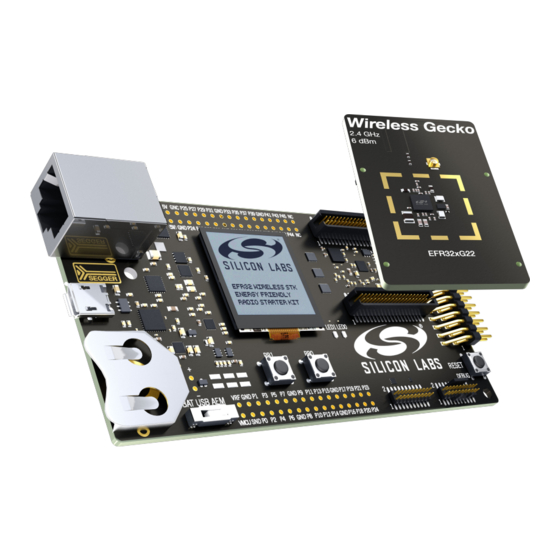
A Wireless Starter Kit with the BRD4183A Radio Board is an ex-
cellent starting point to get familiar with the EFR32™ Wireless
Gecko Wireless System-on-Chip. It also provides all necessary
tools for developing a Silicon Labs wireless application.
BRD4183A is a plug-in board for the Wireless Starter Kit Mainboard. It is a complete ref-
erence design for the EFR32xG22 Wireless SoC, with matching network and a PCB an-
tenna for 6 dBm output power in the 2.4 GHz band.
The Wireless Starter Kit Mainboard contains an on-board J-Link debugger with a Packet
Trace Interface and a Virtual COM port, enabling application development and debug-
ging of the attached radio board as well as external hardware.
This document describes how to use the BRD4183A Radio Board together with a Wire-
less Starter Kit Mainboard.
silabs.com | Building a more connected world.
BRD4183A RADIO BOARD FEATURES
• EFR32xG22 Wireless Gecko Wireless
SoC with 512 kB Flash and 32 kB RAM
(EFR32MG22C224F512IM32).
• Inverted-F PCB antenna (2.4 GHz band)
• 8 Mbit low-power serial flash for over-the-
air upgrades
WIRELESS STK MAINBOARD FEATURES
• Advanced Energy Monitor
• Packet Trace Interface
• Virtual COM port
• SEGGER J-Link on-board debugger
• External device debugging
• Ethernet and USB connectivity
• Low power 128x128 pixel Memory LCD-
TFT
• User LEDs / pushbuttons
• 20-pin 2.54 mm EXP header
• Breakout pads for Wireless SoC I/O
• CR2032 coin cell battery support
SOFTWARE SUPPORT
• Simplicity Studio™
• Energy Profiler
• Network Analyzer
ORDERING INFORMATION
• SLWSTK6021A
• SLWRB4183A
Rev. 1.0
Advertisement
Table of Contents

Related Manuals for Silicon Laboratories EFR32xG22


Summary of Contents for Silicon Laboratories EFR32xG22
- Page 1 BRD4183A is a plug-in board for the Wireless Starter Kit Mainboard. It is a complete ref- • Inverted-F PCB antenna (2.4 GHz band) erence design for the EFR32xG22 Wireless SoC, with matching network and a PCB an- • 8 Mbit low-power serial flash for over-the- tenna for 6 dBm output power in the 2.4 GHz band.
-
Page 2: Table Of Contents
Table of Contents 1. Introduction ....... . 4 1.1 Radio Boards ......4 1.2 Ordering Information . - Page 3 7. Advanced Energy Monitor ......7.1 Introduction .......23 7.2 Theory of Operation .
-
Page 4: Introduction
1. Introduction The EFR32xG22 Wireless Gecko Wireless SoC is featured on a radio board that plugs directly into a Wireless Starter Kit (WSTK) Main- board. The mainboard features several tools for easy evaluation and development of wireless applications. An on-board J-Link debug- ger enables programming and debugging on the target device over USB or Ethernet. -
Page 5: Hardware Overview
UG431: EFR32xG22 2.4 GHz 6 dBm QFN32 Wireless Starter Kit User's Guide Hardware Overview 2. Hardware Overview 2.1 Hardware Layout The layout of the EFR32xG22 2.4 GHz 6 dBm QFN32 Wireless Starter Kit is shown in the figure below. Radio Board Breakout Pads Plug-in Radio Board Si7021 Humidity and... -
Page 6: Block Diagram
UG431: EFR32xG22 2.4 GHz 6 dBm QFN32 Wireless Starter Kit User's Guide Hardware Overview 2.2 Block Diagram An overview of the EFR32xG22 2.4 GHz 6 dBm QFN32 Wireless Starter Kit is shown in the figure below. Board USB Mini-B Controller... -
Page 7: Connectors
UG431: EFR32xG22 2.4 GHz 6 dBm QFN32 Wireless Starter Kit User's Guide Connectors 3. Connectors This chapter gives you an overview of the Wireless STK Mainboard connectivity. The placement of the connectors are shown in the figure below. Ethernet Connector... -
Page 8: Breakout Pads
UG431: EFR32xG22 2.4 GHz 6 dBm QFN32 Wireless Starter Kit User's Guide Connectors 3.3 Breakout Pads Most pins of the EFR32 are routed from the radio board to breakout pads at the top and bottom edges of the Wireless STK Mainboard. -
Page 9: Exp Header
(EXP boards) that can plug into a number of different Silicon Labs Starter Kits. However, due to limitations in the number of available I/O pins on the EFR32xG22, the connector on this kit has a reduced feature set. -
Page 10: Exp Header Pinout
UG431: EFR32xG22 2.4 GHz 6 dBm QFN32 Wireless Starter Kit User's Guide Connectors 3.4.1 EXP Header Pinout The pin-routing on the EFR32 is very flexible, so most peripherals can be routed to any pin. However, many pins are shared between the EXP header and other functions on the Wireless STK Mainboard. -
Page 11: Debug Connector
UG431: EFR32xG22 2.4 GHz 6 dBm QFN32 Wireless Starter Kit User's Guide Connectors 3.5 Debug Connector The debug connector serves multiple purposes based on the "debug mode" setting which can be configured in Simplicity Studio. When the debug mode is set to "Debug IN", the debug connector can be used to connect an external debugger to the EFR32 on the radio board. -
Page 12: Simplicity Connector
UG431: EFR32xG22 2.4 GHz 6 dBm QFN32 Wireless Starter Kit User's Guide Connectors 3.6 Simplicity Connector The Simplicity Connector enables the advanced debugging features, such as the AEM, the virtual COM port, and the Packet Trace Interface, to be used towards an external target. The pinout is illustrated in the figure below. -
Page 13: Debug Adapter
UG431: EFR32xG22 2.4 GHz 6 dBm QFN32 Wireless Starter Kit User's Guide Connectors 3.7 Debug Adapter The BRD8010A STK/WSTK Debug Adapter is an adapter board which plugs directly into the debug connector and the Simplicity Con- nector on the mainboard. It combines selected functionality from the two connectors to a smaller footprint 10-pin connector, which is more suitable for space constrained designs. -
Page 14: Power Supply And Reset
UG431: EFR32xG22 2.4 GHz 6 dBm QFN32 Wireless Starter Kit User's Guide Power Supply and Reset 4. Power Supply and Reset 4.1 Radio Board Power Selection The EFR32 on a Wireless Starter Kit can be powered by one of these sources: •... -
Page 15: Board Controller Power
UG431: EFR32xG22 2.4 GHz 6 dBm QFN32 Wireless Starter Kit User's Guide Power Supply and Reset 4.2 Board Controller Power The board controller is responsible for important features, such as the debugger and the AEM, and is powered exclusively through the USB port in the top left corner of the board. -
Page 16: Peripherals
UG431: EFR32xG22 2.4 GHz 6 dBm QFN32 Wireless Starter Kit User's Guide Peripherals 5. Peripherals The starter kit has a set of peripherals that showcase some of the features of the EFR32. Be aware that most EFR32 I/O routed to peripherals are also routed to the breakout pads or the EXP header. This must be taken into consideration when using these. -
Page 17: Virtual Com Port
UG431: EFR32xG22 2.4 GHz 6 dBm QFN32 Wireless Starter Kit User's Guide Peripherals 5.3 Virtual COM Port An asynchronous serial connection to the board controller is provided for application data transfer between a host PC and the target EFR32. This eliminates the need for an external serial port adapter. -
Page 18: Host Interfaces
UG431: EFR32xG22 2.4 GHz 6 dBm QFN32 Wireless Starter Kit User's Guide Peripherals 5.3.1 Host Interfaces Data can be exchanged between the board controller and the target device through the VCOM interface, which is then available to the user in two different ways: •... -
Page 19: Hardware Handshake
UG431: EFR32xG22 2.4 GHz 6 dBm QFN32 Wireless Starter Kit User's Guide Peripherals 5.3.3 Hardware Handshake The VCOM peripheral supports basic RTS/CTS flow control. VCOM_CTS (target clear to send) is a signal that is output from the board controller and input to the target device. The board controller de-asserts this pin whenever its input buffer is full and it is unable to accept more data from the target device. -
Page 20: Board Controller
UG431: EFR32xG22 2.4 GHz 6 dBm QFN32 Wireless Starter Kit User's Guide Board Controller 6. Board Controller The Wireless STK Mainboard contains a dedicated microcontroller for some of the advanced kit features provided. This microcontroller is referred to as the board controller and is not programmable by the user. The board controller acts as an interface between the host PC and the target device on the radio board, as well as handling some housekeeping functions on the board. -
Page 21: Command Examples
UG431: EFR32xG22 2.4 GHz 6 dBm QFN32 Wireless Starter Kit User's Guide Board Controller 6.1.3 Command Examples PTI Configuration pti config 0 efruart 1600000 Configures PTI to use the "EFRUART" mode at 1.6 Mb/s. Serial Port Configuration serial config vcom handshake enable Enables hardware handshake on the VCOM UART connection. -
Page 22: Troubleshooting
UG431: EFR32xG22 2.4 GHz 6 dBm QFN32 Wireless Starter Kit User's Guide Board Controller 6.2.4 Troubleshooting Problem Solution No data received after ending a After certain debugger operations the host computer manually disables SWO on the target in order debug session. -
Page 23: Advanced Energy Monitor
UG431: EFR32xG22 2.4 GHz 6 dBm QFN32 Wireless Starter Kit User's Guide Advanced Energy Monitor 7. Advanced Energy Monitor 7.1 Introduction Any embedded developer seeking to make their embedded code spend as little energy as the underlying architecture supports needs tools to easily and quickly discover inefficiencies in the running application. -
Page 24: Aem Accuracy And Performance
UG431: EFR32xG22 2.4 GHz 6 dBm QFN32 Wireless Starter Kit User's Guide Advanced Energy Monitor 7.3 AEM Accuracy and Performance The AEM is capable of measuring currents in the range of 0.1 µA to 95 mA. For currents above 250 µA, the AEM is accurate within 0.1 mA. -
Page 25: On-Board Debugger
UG431: EFR32xG22 2.4 GHz 6 dBm QFN32 Wireless Starter Kit User's Guide On-Board Debugger 8. On-Board Debugger The Wireless STK Mainboard contains an integrated debugger, which can be used to download code and debug the EFR32. In addition to programming a target on a plug-in radio board, the debugger can also be used to program and debug external Silicon Labs EFM32, EFM8, EZR32, and EFR32 devices connected through the debug connector. -
Page 26: Debug Modes
UG431: EFR32xG22 2.4 GHz 6 dBm QFN32 Wireless Starter Kit User's Guide On-Board Debugger 8.2 Debug Modes Programming external devices is done by connecting to a target board through the provided debug connector and by setting the debug mode to [Out]. The same connector can also be used to connect an external debugger to the EFR32 Wireless SoC on the kit by setting debug mode to [In]. -
Page 27: Debugging During Battery Operation
UG431: EFR32xG22 2.4 GHz 6 dBm QFN32 Wireless Starter Kit User's Guide On-Board Debugger Note: For "Debug IN" to work, the kit board controller must be powered through the Debug USB connector. 8.3 Debugging During Battery Operation When the EFR32 is powered by battery and the J-Link USB is still connected, the on-board debug functionality is available. If the USB power is disconnected, the Debug IN mode will stop working. -
Page 28: Kit Configuration And Upgrades
UG431: EFR32xG22 2.4 GHz 6 dBm QFN32 Wireless Starter Kit User's Guide Kit Configuration and Upgrades 9. Kit Configuration and Upgrades The kit configuration dialog in Simplicity Studio allows you to change the J-Link adapter debug mode, upgrade its firmware, and change other configuration settings. -
Page 29: Schematics, Assembly Drawings, And Bom
UG431: EFR32xG22 2.4 GHz 6 dBm QFN32 Wireless Starter Kit User's Guide Schematics, Assembly Drawings, and BOM 10. Schematics, Assembly Drawings, and BOM Schematics, assembly drawings, and bill of materials (BOM) are available through Simplicity Studio when the kit documentation pack- age has been installed. -
Page 30: Kit Revision History
UG431: EFR32xG22 2.4 GHz 6 dBm QFN32 Wireless Starter Kit User's Guide Kit Revision History 11. Kit Revision History The kit revision can be found printed on the kit packaging label, as outlined in the figure below. EFR32xG22 2.4 GHz 6 dBm QFN32 Radio Board... -
Page 31: Document Revision History
UG431: EFR32xG22 2.4 GHz 6 dBm QFN32 Wireless Starter Kit User's Guide Document Revision History 12. Document Revision History Revision 1.0 21 February 2020 Initial document version. silabs.com | Building a more connected world. Rev. 1.0 | 31... - Page 32 Trademark Information Silicon Laboratories Inc.® , Silicon Laboratories®, Silicon Labs®, SiLabs® and the Silicon Labs logo®, Bluegiga®, Bluegiga Logo®, ClockBuilder®, CMEMS®, DSPLL®, EFM®, EFM32®, EFR, Ember®, Energy Micro, Energy Micro logo and combinations thereof, "the world’s most energy friendly microcontrollers", Ember®, EZLink®, EZRadio®, EZRadioPRO®, Gecko®, Gecko OS, Gecko OS Studio, ISOmodem®, Precision32®, ProSLIC®, Simplicity Studio®, SiPHY®, Telegesis, the Telegesis Logo®, USBXpress®...
Need help?
Do you have a question about the EFR32xG22 and is the answer not in the manual?
Questions and answers