Moxa Technologies W345 Quick Installation Manual
Hide thumbs
Also See for W345:
- Hardware user manual (29 pages) ,
- Quick installation manual (2 pages) ,
- Quick installation manual (2 pages)
Table of Contents
Advertisement
Quick Links
W345
Quick Installation Guide
Second Edition, April 2008
1. Overview
The W345 embedded computer has four RS-232/422/485 serial ports,
one 10/100 Mbps Ethernet port, an embedded GSM/GPRS module, an
SD socket interface for storage expansion, two USB 2.0 host ports, and
one relay output channel. This combination of features makes the
W345 ideal for your wireless embedded applications.
2. Package Checklist
Before installing W345, verify that the package contains the following
items:
1 W345 embedded computer
Quick Installation Guide
Document & Software CD
Cross-over Ethernet cable: RJ45 to RJ45, 100 cm
Console port cable: CBL-4PINDB9F-100, 4-pin header to
female DB9 cable
1 dBi antenna
Universal Power Adaptor
Product Warranty Statement
Optional Accessories
35 mm DIN-Rail Mounting Kit (DK-35A)
Please notify your sales representative if any of the above items are
missing or damaged.
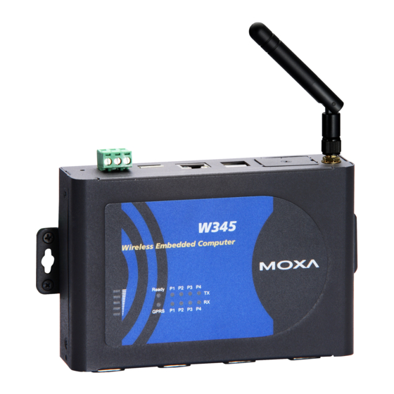
3. W345 Panel Layout
The W345 comes with four RS-232/422/485 serial ports, one RS-232
console port, one 10/100 Mbps LAN port, an embedded GSM/GPRS
module, an SD socket interface for storage expansion, two USB 2.0 host
ports, and one relay output channel. The following figures show the panel
layouts of the W345.
P/N: 1802003450011
— 1 —
Top View
Reset Button
Relay Output
USB 2.0 Host
Ethernet
12 to 48 VDC
10/100BaseTX
Front View
USB 2.0 Host x 2
Ethernet
(10/100BaseTx)
Relay Output
12 to 48 VDC
5
Serial Port 1 to 4
(RS-232/422/485)
Bottom View
— 2 —
LED Indicators
The following table describes the LED indicators located on the front
1. Internal SD Slot for
Storage Expansion
panel of the W345.
2. Internal SIM Card Slot
(remove cover to access)
LED Name
Ready
SD
Wireless GSM/GPRS
antenna connector
GSM/GPRS
Wireless
GSM/GPRS
antenna
Signal
Strength
1. Internal SD Slot for
Storage Expansion
2. Internal SIM Card Slot
(remove cover to access)
LAN
TxD
P1-P4
RxD
Serial
P1-P4
console port
4. Installing the W345
Wall or Cabinet Mounting
The W345 embedded computers have built-in "ears"
for attaching the embedded computers to a wall or
the inside of a cabinet. We suggest using two screws
per ear to attach the W345 to a wall or cabinet. The
heads of the screws should be less than 6.0 mm in
diameter, and the shafts should be less than 3.5 mm
in diameter, as shown by the figure at the right.
DIN-Rail Mounting
DIN-rail attachments can be purchased separately to attach the product to
Serial Ports x 4
(RS-232/422/485)
a DIN-rail. When snapping the attachments to the DIN-rail, make sure
that the stiff metal springs are at the top.
LED Color
LED Function
Green
Power is on and functioning normally
Off
Power is off or power error exists
SD card is detected
Green
Off
SD card is not detected
ON:
GPRS is ready
Green
Blinking: Conflict with GPRS IP, or
DHCP server not responding
Off
GPRS is not ready or function error exists
Number of glowing LEDs indicates signal
strength:
5: Excellent
Green
4: Very good
3: Good
2: Fair
1: Bad
Off
No signal, or GPRS connection failed
Orange
10 Mbps Ethernet link
Green
100 Mbps Ethernet link
Off
Disconnected or short circuit
Green
Serial ports P1-P4 transmitting data
Off
Serial ports P1-P4 not transmitting data
Yellow
Serial ports P1-P4 receiving data
Off
Serial ports P1-P4 not receiving data
6.0 mm
3.5 mm
— 3 —
Advertisement
Table of Contents

Related Manuals for Moxa Technologies W345


Summary of Contents for Moxa Technologies W345
- Page 1 We suggest using two screws Bottom View missing or damaged. per ear to attach the W345 to a wall or cabinet. The 3.5 mm heads of the screws should be less than 6.0 mm in 3.
- Page 2 Ready LED will light up. 7. Connecting the W345 to a PC There are two ways to connect the W345 to a PC: (1) through the serial SD Slot console port, or (2) by Telnet over the network. The COM settings for the 5.
Need help?
Do you have a question about the W345 and is the answer not in the manual?
Questions and answers