Table of Contents
Advertisement
Advertisement
Table of Contents

Related Manuals for GE HEALTHCARE AKTAprime plus


Summary of Contents for GE HEALTHCARE AKTAprime plus
- Page 1 ÄKTAprime plus Operating Instructions Original instructions...
-
Page 2: Table Of Contents
Table of Contents Table of Contents Introduction ......................Important user information ......................Regulatory information ........................Instrument ............................... Monitoring and evaluation ....................... User documentation ........................... Safety instructions ....................Safety precautions ..........................Labels ................................. Emergency procedures ........................Recycling information ......................... Declaration of Hazardous Substances (DoHS) ................ Installation ...................... - Page 3 Table of Contents Reference information ..................Specifications ............................Chemical resistance ..........................System recommendations ....................... Health and Safety Declaration Form ................... Ordering information .......................... Appendix A Connection diagram - Liquid flow path ......... Appendix B Tubing ....................ÄKTAprime plus Operating Instructions 28-9597-89 AC...
-
Page 4: Introduction
1 Introduction Introduction Purpose of the Operating Instructions The Operating Instructions provide you with the instructions needed to handle ÄKTAprime plus in a safe way. Prerequisites In order to operate ÄKTAprime plus as is intended, the following pre-requisites must be fulfilled: ®... -
Page 5: Important User Information
1 Introduction 1.1 Important user information Important user information Read this before operating the product All users must read the entire Operating Instructions before installing, operating or maintaining the product. Always keep the Operating Instructions at hand when operating the product. Do not operate the product in any other way than described in the user documentation. -
Page 6: Regulatory Information
1 Introduction 1.1 Important user information Cautions CAUTION CAUTION indicates a hazardous situation which, if not avoided, could result in minor or moderate injury. It is important not to proceed until all stated conditions are met and clearly understood. Notices NOTICE NOTICE indicates instructions that must be followed to avoid damage to the product or other equipment. - Page 7 EU Declaration of Conformity (DoC) document. Requirement Content Name and address of manufacturer GE Healthcare Bio-Sciences AB, Björkgatan 30, SE 751 84 Uppsala, Sweden Conformity with EU Directives This product complies with the European directives listed in the table, by fulfilling the corresponding harmonized standards.
- Page 8 1 Introduction 1.2 Regulatory information International standards This product fulfills the requirements of the following standards: Standard Description Notes EN/IEC 61010-1, Safety requirements for electrical EN standard is harmonized UL 61010-1, equipment for measurement, with EU directive CAN/CSA-C22.2 control, and laboratory use 2006/95/EC No.
-
Page 9: Instrument
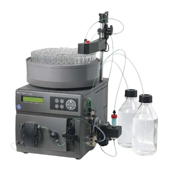
1 Introduction 1.2 Regulatory information Environmental conformity This product conforms to the following environmental requirements. Requirement Title 2011/65/EU Restriction of Hazardous Substances (RoHS) Directive 2012/19/EU Waste Electrical and Electronic Equipment (WEEE) Directive ACPEIP Administration on the Control of Pollution Caused by Electronic Information Products, China Restriction of Hazardous Sub- stances (RoHS) Regulation (EC) - Page 10 1 Introduction 1.3 Instrument Part Function Part Function Fraction collector Switch valve Monitor and controller Conductivity cell LCD display Flow restrictor Push buttons UV flow cell Pump Column Pressure sensor Sample loop Mixer Flow diversion valve Injection valve Column holder Buffer valve The Power switch is located at the rear of the system.
- Page 11 1 Introduction 1.3 Instrument Connection Connection Fraction collector Optical unit Measurement data to recorder Power switch On/off signals to recorder Mains power inlet UV lamp Navigation menu The system is operated from the push buttons and LCD display at the front panel. hold /cont feed...
- Page 12 1 Introduction 1.3 Instrument Button Description feed tube Advance the fraction collector one position. Basic flow path Figure 1.3: Basic flow path. Stage Part Description P, V1 Pump P pumps buffer from a buffer container connected to the buffer valve V1. SW, B To form a gradient the switch valve (SW) can be used to pull liquid from buffer container (B).
-
Page 13: Monitoring And Evaluation
1 Introduction 1.4 Monitoring and evaluation Monitoring and evaluation PrimeView ™ software PrimeView is a software that allows real time monitoring, evaluation and report generation on an external computer. For more information about PrimeView evaluation system and instructions for installation, see the PrimeView User Manual supplied. - Page 14 1 Introduction 1.5 User documentation User documentation Content ÄKTAprime plus training video Covers the system introduction, step by step installation, setting-up the run and evaluation of results. EU Declaration of Conformity for Document whereby the manufacturer ÄKTAprime plus ensures that the product satisfies and is in conformity with the essential require- ments of the applicable directives.
-
Page 15: Safety Instructions
2 Safety instructions Safety instructions About this chapter This chapter describes safety compliance, safety labels, general safety precautions, emergency procedures, power failure and recycling of ÄKTAprime plus. Safety precautions Introduction The ÄKTAprime plus instrument is powered by mains voltage and handles pressurized liquids that may be hazardous. - Page 16 2 Safety instructions 2.1 Safety precautions WARNING Operation and user maintenance of the ÄKTAprime plus instrument should be performed by properly trained personnel only. WARNING Before connecting a column to the ÄKTAprime plus instrument, read the instructions for use of the column. To avoid exposing the column to excessive pressure, make sure that the pressure limit is set to the specified maximum pressure of the column.
- Page 17 2 Safety instructions 2.1 Safety precautions NOTICE Avoid condensation by letting the unit equilibrate to ambient tem- perature. Using flammable liquids When using flammable liquids with the ÄKTAprime plus instrument, follow these precau- tions to avoid any risk of fire or explosion. WARNING Fire Hazard.
- Page 18 WARNING ÄKTAprime plus must always be connected to a grounded power outlet. WARNING Power cord. Only use power cords with approved plugs delivered or approved by GE Healthcare. ÄKTAprime plus Operating Instructions 28-9597-89 AC...
- Page 19 2 Safety instructions 2.1 Safety precautions WARNING Access to power switch and power cord with plug. Do not block access to the power switch and power cord. The power switch must always be easy to access. The power cord with plug must always be easy to disconnect.
- Page 20 2 Safety instructions 2.1 Safety precautions WARNING Hazardous biological agents during run. When using hazardous biological agents, run System CIP and Column CIP to flush the entire system tubing with bacteriostatic solution (e.g. NaOH) fol- lowed by a neutral buffer and finally distilled water, before service and maintenance.
- Page 21 2.1 Safety precautions Maintenance WARNING Electrical shock hazard. All repairs should be done by service personnel authorized by GE Healthcare. Do not open any covers or replace parts unless specifically stated in the user documenta- tion. WARNING Disconnect power. Always disconnect power from the instrument before replacing any component on the instrument, unless stated otherwise in the user documentation.
- Page 22 2 Safety instructions 2.1 Safety precautions WARNING NaOH is corrosive and therefore dangerous to health. When using hazardous chemicals, avoid spillage and wear protective glasses and other suitable Personal Protective Equipment (PPE). WARNING After assembly, the piping system must be tested for leakage at maximum pressure for continued protection against injury risks due to fluid jets, burst pipes or explosive atmosphere.
-
Page 23: Labels
2 Safety instructions 2.1 Safety precautions NOTICE Cleaning. Keep the instrument dry and clean. Wipe regularly with a soft damp tissue and, if necessary, a mild cleaning agent. Let the instrument dry completely before use. Labels In this section This section describes the instrument labels and labels concerning hazardous substances that are attached to the ÄKTAprime plus instrument. - Page 24 2 Safety instructions 2.2 Labels Symbols used in instrument labels Label Meaning Warning! Read the user documentation before using the equipment. Do not open any covers or replace parts unless specifically stated in the user documentation. The equipment complies with the requirements for electromagnetic compliance (EMC) in Australia and New Zealand.
-
Page 25: Emergency Procedures
2 Safety instructions 2.2 Labels Label Meaning This symbol indicates that the product contains hazardous materials in excess of the limits established by the Chinese standard SJ/T11363-2006 Requirements for Concentration Limits for Certain Hazardous Substances in Electronics. Emergency procedures In this section This section describes how to do an emergency shutdown of the ÄKTAprime plus system. -
Page 26: Recycling Information
2 Safety instructions 2.4 Recycling information Recycling information Decontamination ÄKTAprime plus shall be decontaminated before decommissioning and all local regula- tions shall be followed with regard to scrapping of the equipment. Disposal, general instructions When taking ÄKTAprime plus out of service, the different materials must be separated and recycled according to national and local environmental regulations. -
Page 27: Declaration Of Hazardous Substances (Dohs)
2 Safety instructions 2.5 Declaration of Hazardous Substances (DoHS) Declaration of Hazardous Substances (DoHS) 根据SJ/T11364-2006《电子信息产品污染控制标识要求》特提供如下有关污染 控制方面的信息。 The following product pollution control information is provided according to SJ/T11364-2006 Marking for Control of Pollution caused by Electronic Information Products. 电子信息产品污染控制标志说明 Explanation of Pollution Control Label 该标志表明本产品含有超过SJ/T11363-2006《电子信息产品中有毒有害物质的限... - Page 28 2 Safety instructions 2.5 Declaration of Hazardous Substances (DoHS) 有毒有害物质或元素的名称及含量 Name and Concentration of Hazardous Substances 产品中有毒有害物质或元素的名称及含量 Table of Hazardous Substances’ Name and Concentration 部件名称 有毒有害物质或元素 Component name Hazardous substance 铅 汞 镉 六价铬 多溴联苯 多溴二苯醚 Cr6+ PBDE 11-0013-13 表示该有毒有害物质在该部件所有均质材料中的含量均在SJ/T11363-2006 标准规定的限 量要...
-
Page 29: Installation
3 Installation Installation ÄKTAprime plus is delivered in protective packing material and shall be unpacked with great care. Any equipment connected to ÄKTAprime plus must fulfill applicable standards and local regulations. A video describing the installation process, is supplied with each ÄKTAprime plus system. For detailed information on Installation, see ÄKTAprime plus User Manual. -
Page 30: Unpacking
3 Installation 3.2 Transport NOTICE Lift the instrument in the upright position. Do not use the fraction- ation arm as a lifting handle. Before moving the system: • disconnect all cables and tubing connected to peripheral components and liquid containers. •... -
Page 31: Spare Parts And Accessories
3 Installation 3.4 Connections Flow path All parts and tubing are mounted on the system at delivery. Connect a waste tube, buffer and sample bottles, and optional accessories. Electrical power Connect the power cord to a grounded power outlet specified in Section 3.1 Site require- ments, on page Spare parts and accessories... -
Page 32: Operation
4 Operation Operation About this chapter This chapter provides instructions for the use of ÄKTAprime plus. Operation overview Workflow The typical workflow in ÄKTAprime plus, after turning on the system, can be divided into a number of steps. Step Action Section Prepare the system for a run Section 4.3 Preparations before start, on page 33... -
Page 33: Preparations Before Start
4 Operation 4.2 Starting the instrument 4 The self-test takes about 30–40 seconds. When the test is completed, the display shows the Templates menu. Note: The system can be used for most applications after 15 min of lamp warm-up but the full specifications are not obtained until after 1 hour. Preparations before start Buffer preparation Prepare buffers according to ÄKTAprime plus cue cards. - Page 34 4 Operation 4.3 Preparations before start 6 Choose to wash the A2–A8 inlet tubing that is used by pressing OK at those cursor positions. A1 and B will always be washed. Note: At delivery, only A1 and B are installed. 7 Scroll to OK and press the OK button.
- Page 35 4 Operation 4.3 Preparations before start 2 Press OK. The switch valve turns to the inlet B port. 3 Draw buffer with the purge syringe until liquid enters the syringe. 4 Replace the purge tubing with the stop plug. 5 Stop the pump by pressing end and then OK. Flushing the pump with 100% ethanol: 1 Put inlet tubing A1 in deionized water.
- Page 36 4 Operation 4.3 Preparations before start Description Description Tubing from injection valve HisTrap column 1/16" male connector UV cell Note: Other unions and connectors might be required for other columns. Preparing the fraction collector 1 Fill the fraction collector rack with, for example, 18 mm tubes (minimum 40 pcs.). 2 Adjust the height of the delivery arm using the lock knob (1) so that the bottom of the tube sensor (2) is about 5 mm below the top of the tubes.
- Page 37 4 Operation 4.3 Preparations before start 4 Check that the tube sensor (1) is in the correct position for the tube size. The eluent tubing should be over the center of the collection tube. Use the red sensor control knob (2) to position the tube holder (3). 5 Rotate the rack by hand until the rear half of the tube sensor rests against the first tube.
-
Page 38: Performing A Run
4 Operation 4.3 Preparations before start 1 Connect a sample loop between port 2 and 6 on the injection valve. Make sure that the sample loop is large enough for your sample. 2 Connect a luer female/1/16" male union to port 3. 3 Fill a syringe with five loop volumes of deionized water or binding buffer. - Page 39 4 Operation 4.4 Performing a run Viewing the run When the pump starts running, the progress of the run can be viewed in the two panes in PrimeView. • The Curves pane displays monitor signal values graphically. • The Logbook pane displays all actions (e.g. method start and end, base instructions and method instructions) and unexpected conditions (e.g.
-
Page 40: Procedures After A Run
4 Operation 4.4 Performing a run Ending the run Press OK at the Method Complete prompt. This will cause all valves to return to their default positions. To stop the run on a system before it is finished: 1 Press the end button. 2 Select yes and press OK. - Page 41 4 Operation 4.5 Procedures after a run NOTICE Do not allow particles to enter the UV flow cell as damage to the flow cell might occur. Buffers not containing any salt can be left in the system for a short time after a run, even overnight (not in the pH electrode, see instructions below).
-
Page 42: Maintenance
For maintenance of a specific component, carefully read the component manual and follow the instructions. WARNING Electrical shock hazard. All repairs should be done by service personnel authorized by GE Healthcare. Do not open any covers or replace parts unless specifically stated in the user documenta- tion. WARNING Disconnect power. -
Page 43: User Maintenance Schedule
5 Maintenance 5.1 General WARNING Do not perform any type of maintenance work while the system is powered electrically or when the piping system is pressurized. Note that the piping system can be pressurized even when the system is closed down. WARNING When using hazardous chemical and biological agents, take all suitable protective measures, such as wearing protective glasses... - Page 44 5 Maintenance 5.2 User maintenance schedule Table 5.1: User maintenance schedule Interval Action Instructions/reference Daily Leak inspection Visually inspect the system for leaks. Wash the system flow 1 For cleaning the flow path, see Cleaning-In- path Place, on page 2 For leaving the system for a few days, see Section 5.7 Storage, on page Calibrate pH electrode Calibrate the pH electrode (if applicable) accord-...
-
Page 45: Cleaning
5 Maintenance 5.2 User maintenance schedule Interval Action Instructions/reference Yearly Valve inspection Check for external or internal leakage. Replace channel plate and distribution plate yearly or when required. Refer to the relevant valve in- struction sheet. Cleaning Cleaning before planned maintenance/service To ensure the protection and safety of service personnel, all equipment and work areas must be clean and free of any hazardous contaminants before a Service Engineer starts... -
Page 46: Component Maintenance
The operator must carefully read and understand the instructions supplied for each component before disassembly and assembly of the component. When replacing con- sumables, such as tubing and tubing connectors, all neccessary safety precautions must be taken. Contact your local GE Healthcare representative if further information or help is needed. WARNING Disconnect power. -
Page 47: Calibration
5 Maintenance 5.5 Disassembly and assembly of components and consumables WARNING Before disassembly, check that there is no pressure in the piping system. WARNING After assembly, the piping system must be tested for leakage at maximum pressure for continued protection against injury risks due to fluid jets, burst pipes or explosive atmosphere. -
Page 48: Storage
5 Maintenance 5.7 Storage Storage General recommendation For storage, the system must first be cleaned as described in Cleaning-In-Place, on page 45. After cleaning, the system must be filled with 0.01 M NaOH or 20% ethanol solution. Columns and media shall be stored according to their respective instructions. Storage conditions The following conditions shall be maintained while the system is in storage: •... -
Page 49: Troubleshooting
6 Troubleshooting Troubleshooting UV curve problems Error symptom Possible cause Corrective action Ghost peak Dirt or residues in the Clean the system. Make sure air is flow path from previ- removed. ous runs. Air in the eluents. Residue in the column Clean the column according to the from previous runs column instructions. -
Page 50: Conductivity Curve Problems
6 Troubleshooting 6.1 UV curve problems Error symptom Possible cause Corrective action Low sensitivity Aging UV lamp Check the lamp run time according to and replace if necessary. Refer to ÄKTAprime plus User Manual. UV lamp in wrong po- Check that the lamp position and sition the filter position are both set to the wavelength to be used, 280 nm... - Page 51 6 Troubleshooting 6.2 Conductivity curve problems Error symptom Possible cause Corrective action Waves on the gradi- Incorrect pump func- Check that the pump is operating tion and is programmed correctly. Dirty mixing chamber Check that the mixing chamber is free from dirt or particles. Insufficient mixing Change to a larger mixing cham- chamber volume...
-
Page 52: Ph Curve Problems
6 Troubleshooting 6.2 Conductivity curve problems Error symptom Possible cause Corrective action Incorrect or unstable Loose connection of Check that the conductivity flow reading conductivity flow ca- cell cable is connected properly. Incorrect pump and Check that the pump and valves valves function operate correctly. - Page 53 6 Troubleshooting 6.3 pH curve problems Error symptom Possible cause Corrective action Slow pH response or Contaminated elec- Check the electrode glass mem- Calibration impossible trode glass mem- brane. If it is contaminated, clean brane the electrode following the instruc- tions in Monitor pH/C-900 User Manual.
- Page 54 6 Troubleshooting 6.3 pH curve problems Error symptom Possible cause Corrective action Incorrect or unstable Problem with elec- Check that the electrode cable is pH reading trode connected properly. Check that the electrode is correct- ly inserted in the flow cell and, if necessary, hand-tighten the nut.
-
Page 55: Pressure Curve Problems
6 Troubleshooting 6.3 pH curve problems Error symptom Possible cause Corrective action pH values vary with Problem with the Replace the pH electrode. varied back pressure electrode Pressure curve problems Error symptom Possible cause Corrective action Erratic flow, noisy Air bubbles passing Check all connections for leaks. -
Page 56: Reference Information
7 Reference information Reference information About this chapter This chapter contains technical data, regulatory and other information. Specifications Parameter Value Ingression protection Housing: IP20 Flow cells: IP44 Supply voltage 100-120/220-240 V AC ±10% autorange , 50 to 60 Hz Transient overvoltages Overvoltage category II Power consumption 90 VA... -
Page 57: Chemical Resistance
7 Reference information 7.2 Chemical resistance Chemical resistance Chemical Exposure Exposure CAS no. EEC no. Comments < 1 day up to 2 months Acetaldehyde Acetic acid, < 5% Acetic acid, 70% 64-19-7 200-580-7 Acetonitrile 75-05-8 200-835-2 PP and PE swell. Acetone, 10% Avoid PVDF is affected by... - Page 58 7 Reference information 7.2 Chemical resistance Chemical Exposure Exposure CAS no. EEC no. Comments < 1 day up to 2 months Ethanol, 100% 75-08-1 200-837-3 Ethyl acetate Avoid Silicone not resis- tant. Pressure limit for PEEK decreases. Ethylene glycol, 107-21-1 203-473-3 100% Formic acid, 100%...
- Page 59 7 Reference information 7.2 Chemical resistance Chemical Exposure Exposure CAS no. EEC no. Comments < 1 day up to 2 months Potassium chloride 7447-40-7 231-211-8 Pyridine Avoid Avoid ETFE, PP and PE not resistant. Sodium acetate Sodium bicarbon- Sodium bisulphate Sodium borate Sodium carbonate Sodium chloride...
-
Page 60: System Recommendations
7 Reference information 7.2 Chemical resistance Chemical Exposure Exposure CAS no. EEC no. Comments < 1 day up to 2 months Urea, 8M 57-13-6 200-315-5 o-Xylene and p-Xy- Avoid PP and PE are af- lene fected by long term use. System recommendations Refer to ÄKTAprime plus User Manual, or contact your local GE representative for the most current information. -
Page 61: Health And Safety Declaration Form
7 Reference information 7.4 Health and Safety Declaration Form Health and Safety Declaration Form On site service On Site e Servic ce Hea lth & Safety y Declar ration F Form Serv vice Ticket # To ma ke the mutual protection an nd safety of GE E service perso... - Page 62 7 Reference information 7.4 Health and Safety Declaration Form Product return or servicing Healt th & Safe ety Dec laration n Form for Pr roduct R Return o or Servic cing Retu rn authorizat and/or numb ber: Service Ticket t/Request: To ma ke sure the mu utual protectio...
-
Page 63: Ordering Information
7 Reference information 7.5 Ordering information Ordering information For ordering information visit www.gelifesciences.com/AKTA. ÄKTAprime plus Operating Instructions 28-9597-89 AC... -
Page 64: Appendix A Connection Diagram - Liquid Flow Path
A Connection diagram - Liquid flow path Appendix A Connection diagram - Liquid flow path Flow path and components Cond 1100 1000 1250 1250 1000 Description Description Buffers Loop (500 μl) Buffer valve Waste Gradient switch valve Column System pump Male/Male Pressure monitor Flow restrictor (0.2 MPa) -
Page 65: Appendix B Tubing
B Tubing Appendix B Tubing Names in the Label column in Table B.1 refer to tubing labels in the liquid flow path connection diagram, see Appendix A Connection diagram - Liquid flow path, on page Table B.1: Tubing specifications for ÄKTAprime plus Label Material Length... - Page 66 All goods and services are sold subject to the terms and conditions of sale of the company within GE Healthcare which supplies them. A copy of these terms and conditions is available on request. Contact your local GE Healthcare repre- sentative for the most current information.
Need help?
Do you have a question about the AKTAprime plus and is the answer not in the manual?
Questions and answers