Table of Contents
Advertisement
Advertisement
Table of Contents

Related Manuals for GE HEALTHCARE Monitor UV-900


Summary of Contents for GE HEALTHCARE Monitor UV-900
- Page 1 Monitor UV-900 Operating Instructions Original instructions...
-
Page 2: Table Of Contents
Restart after power failure ....................... Maintenance ......................Cleaning before planned service ....................Cleaning the instrument housing ....................User maintenance schedule ......................Cleaning-in-place ..........................Checking the instrument ........................Cleaning the flow cell and optical connectors ................ Monitor UV-900 Operating Instructions 28962214 AD... - Page 3 Troubleshooting ....................General ..............................Faults and actions ..........................Error messages ............................Reference information ..................Technical specifications ........................Health and Safety Declaration Form ................... Menu overview ............................Accessories and spare parts ......................Ordering information .......................... Monitor UV-900 Operating Instructions 28962214 AD...
-
Page 4: Introduction
1 Introduction Introduction About this chapter This chapter contains important user information, descriptions of safety notices, regula- tory information, intended use of the Monitor UV-900 system, and lists of associated documentation. In this chapter Section See page 1.1 About this manual 1.2 Important user information... -
Page 5: Important User Information
Intended use Monitor UV-900 is a UV-absorbtion monitor for use in liquid chromatograhy. Monitor UV-900 is intended for research use only, and shall not be used in any clinical procedures, or for diagnostic purposes. Prerequisites In order to operate Monitor UV-900 in the way it is intended: •... -
Page 6: Regulatory Information
Tip: A tip contains useful information that can improve or optimize your procedures. Regulatory information Introduction This section lists the regulations and standards that apply to the Monitor UV-900. Monitor UV-900 Operating Instructions 28962214 AD... -
Page 7: Eu Directives
If not included with the product, a copy of the EU Declaration of Conformity is available on request. Directive Title 2006/42/EC Machinery Directive (MD) 2014/30/EU Electromagnetic Compatibility (EMC) Directive 2014/35/EU Low Voltage Directive (LVD) 2011/65/EU Restriction of Hazardous Substances (RoHS) Directive Monitor UV-900 Operating Instructions 28962214 AD... -
Page 8: Eurasian Customs Union
GE Healthcare Life Sciences Presnenskaya nab., 10C, 12th floor RU-123 317 Moscow, Russian Federation Telephone 1: + 7 495 411 9714 Fax nr: + 7 495 739 6932 Email: LSrus@ge.com Monitor UV-900 Operating Instructions 28962214 AD... -
Page 9: Regulations For Usa And Canada
This product complies with the Canadian standard ICES-001/NMB-001 concerning electromagnetic compatibility. 1.3.4 Other regulations and standards Introduction This section describes the standards that apply to the Monitor UV-900 system. Environmental conformity This product conforms to the following environmental requirements. Requirement Title... -
Page 10: User Documentation
Generators (Canada) User documentation In addition to these Operating Instructions, the documentation package supplied with Monitor UV-900 also includes product documentation binders containing detailed specifications and traceability documents. The most important documents in the document package with regard to technical aspects of Monitor UV-900 are listed below. - Page 11 EU Declaration of Conformity for Document whereby the manufacturer ensures Monitor UV-900 that the product satisfies and is in conformity with the essential requirements of the applicable direc- tives. Monitor UV-900 Operating Instructions 28962214 AD...
-
Page 12: Safety Instructions
Safety precautions Introduction The Monitor UV-900 is powered by mains voltage and handles pressurized liquids that may be hazardous. Before installing, operating or maintaining the monitor, you must be aware of the hazards described in this manual. Follow the instructions provided to avoid personal injury or damage to the equipment. - Page 13 WARNING Do not use any accessories not supplied or recommended by GE. WARNING Do not use Monitor UV-900 if it is not working properly, or if it has suffered any damage, for example: • damage to the power cord or its plug •...
- Page 14 2 Safety instructions 2.1 Safety precautions Using flammable liquids When using flammable liquids with the Monitor UV-900, follow these precautions to avoid any risk of fire or explosion. WARNING Fire Hazard. Before starting the system, make sure that there is no leakage.
- Page 15 High intensity UV light. This product uses high intensity ultra-violet light. Do not disconnect the optical fibers while the lamp is on. CAUTION Make sure that the system is placed on a stable, level bench with adequate space for ventilation. Monitor UV-900 Operating Instructions 28962214 AD...
- Page 16 WARNING Use only approved parts. Only spare parts and accessories that are approved or supplied by GE may be used for maintaining or servicing the product. Monitor UV-900 Operating Instructions 28962214 AD...
-
Page 17: Labels
Disconnect power. Always disconnect power from the instrument before replacing any component on the instrument, unless stated otherwise in the user documentation. Labels Introduction This section describes the system label on Monitor UV-900 and its meaning. Monitor UV-900 Operating Instructions 28962214 AD... - Page 18 This symbol indicates that waste electrical and electron- ic equipment must not be disposed as unsorted munic- ipal waste and must be collected separately. Please contact an authorized representative of the manufac- turer for information concerning the decommissioning of equipment. Monitor UV-900 Operating Instructions 28962214 AD...
-
Page 19: Emergency Procedures
29 of the Code of Federal Regulations (29 CFR), Part 1910.7. Emergency procedures Introduction This section describes how to perform an emergency shutdown of Monitor UV-900. The section also describes the result in the event of power failure. Monitor UV-900 Operating Instructions 28962214 AD... -
Page 20: Procedures For Decommissioning
In the event of power failure the run is interrupted immediately. Procedures for decommissioning Introduction This section contains information about the decommissioning of Monitor UV-900. Decontamination The product must be decontaminated before decommissioning. All local regulations must be followed with regard to scrapping of the equipment. -
Page 21: Declaration Of Hazardous Substances (Dohs)
The unit of the period is “Year”. Monitor UV-900 Operating Instructions 28962214 AD... - Page 22 Periodic replacement of those consumables or parts to maintain the declared EFUP shall be done in accordance with the Product Maintenance Procedures. This product must not be disposed of as unsorted municipal waste, and must be collected separately and handled properly after decommissioning. Monitor UV-900 Operating Instructions 28962214 AD...
- Page 23 Indicates that this hazardous substance contained in at least one of the homo- geneous materials used for this part is above the limit requirement in GB/T 26572 Data listed in the table represents best information available at the time of • publication. Monitor UV-900 Operating Instructions 28962214 AD...
-
Page 24: System Description
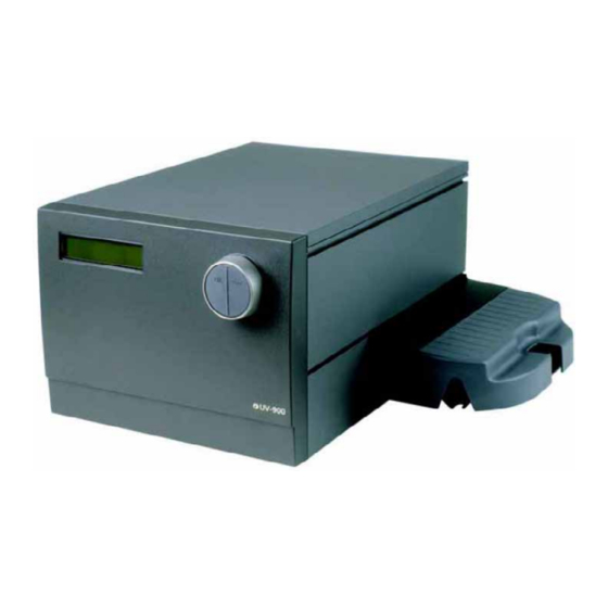
Two alternative flow cells with path length 2 mm and 10 mm. • Accurate and reliable monitoring through self-test, self-calibration and fiber optics. Illustrations Main unit Part Function Display Menu selection dial Cell holder Flow cell Monitor UV-900 Operating Instructions 28962214 AD... -
Page 25: Flow Cell
The optical path length of the flow cell is 2 mm and 10 mm. The flow cell is made of quartz with a titanium housing. The illustration below highlights the optical path cell length (CL). Monitor UV-900 Operating Instructions 28962214 AD... - Page 26 This maintains a high intensity of light to the detector. The long path length combined with a small cell volume increases sensitiv- ity. Optional flow cells The following flow cells can also be used with Monitor UV-900: • UV cell, 1/2/5 mm (ÄKTApilot) •...
-
Page 27: Monitor Principle
3 System description 3.3 Monitor principle Monitor principle Functional diagram of the UV monitor Part Function Flash lamp 100 Hz Condensor Blocking filter Aberration corrected holographic grating Monochromator Monitor UV-900 Operating Instructions 28962214 AD... - Page 28 50% of the light passing through the sample fiber (S) and the flow cell, and 50% being directed through the reference fiber (R). Two photodiodes with identical characteristics monitor the intensities of the sample and reference beams. Monitor UV-900 Operating Instructions 28962214 AD...
- Page 29 Calibration At calibration the instrument automatically finds two persistent lines in the spectrum of Xenon. The wavelengths of these known lines are used to calibrate the stepper motor that turns the grating. Monitor UV-900 Operating Instructions 28962214 AD...
-
Page 30: Installation
4 Installation Installation About this chapter This chapter provides required information to enable users and service personnel to unpack, install, move and transport Monitor UV-900. Precautions WARNING Before attempting to perform any of the procedures described in this chapter, you must read and understand all contents of the... -
Page 31: Unpacking
The instrument should not be used in a corrosive atmosphere or in an atmosphere where deposits are liable to form on the optical surfaces. Transport Before moving the equipment: disconnect all connected cables and tubing. Assembly The following parts must be added to Monitor UV-900 before use: • Flow cell • Optical fibers... - Page 32 Slide the rear white clip on the cell holder to its inner position for a 2 mm cell and to its outer position for a 10 mm cell. Monitor UV-900 Operating Instructions 28962214 AD...
- Page 33 Placing the flow cell with the serial number facing sideways. Connecting the optical fibers WARNING High intensity UV light. This product uses high intensity ultra-violet light. Do not disconnect the optical fibers while the lamp is on. Monitor UV-900 Operating Instructions 28962214 AD...
- Page 34 30% isopropanol using lens papers. NOTICE Do not twist the optical fibers during tightening. Step Action Remove the two black protective caps from the optical fiber connectors. Monitor UV-900 Operating Instructions 28962214 AD...
- Page 35 Slide the rubber sleeves on the two optical fibers onto the connectors. Make sure that the sleeves are pushed tight to the housing to prevent dust, fluid or light entering the connection. Monitor UV-900 Operating Instructions 28962214 AD...
- Page 36 Remove the red protective caps from the inlet and outlet of the flow cell. The inlet is on the top of the flow cell, the same side as the serial number. Connect the tubing with 1/16" fingertight connectors. Monitor UV-900 Operating Instructions 28962214 AD...
-
Page 37: Connecting Electrical Cables
Lower the cover over the cell holder. Connecting electrical cables NOTICE The mains power to Monitor UV-900 must be switched off before connecting the instrument to any cells or external equipment. Monitor UV-900 Operating Instructions 28962214 AD... - Page 38 Any computer used with the equipment shall comply with IEC 60950 and be installed and used according to the manufacturer's instruc- tions. Connect any auxiliary equipment to the Remote socket, 9-pole D–Sub female (5 V TTL signals only). Monitor UV-900 Operating Instructions 28962214 AD...
- Page 39 PC and the termination plug. The UniNet-1 link connects, in series, the PC with Pump P-905, Monitor pH/C-900 and Monitor UV-900. The termination plug is connected to the last instrument in the chain.
- Page 40 Connect a mains cable between the instrument and a grounded mains socket. The instrument is delivered with both European and US type mains cables, as standard. Any voltage 100 to 240 VAC, 50 to 60 Hz, can be used. Monitor UV-900 Operating Instructions 28962214 AD...
-
Page 41: Operation
5 Operation Operation About this chapter This chapter provides the information required to safely operate Monitor UV-900. Precautions WARNING Before attempting to perform any of the procedures described in this chapter, you must read and understand all contents of the... -
Page 42: Starting The Instrument
The display for the third wavelength is reached by turning the dial clockwise. As an alternative, all 3 wavelengths can be shown in a single display, but limited to 3 decimals. This alternative is reached by turning the dial clockwise. Monitor UV-900 Operating Instructions 28962214 AD... -
Page 43: Menu Selection And Settings
Press OK button to select sub-menu. Press ESC button to return one menu level. If a menu has sub levels, the sub menu is displayed by pressing the OK button. Pressing the ESC button moves back one menu level. Monitor UV-900 Operating Instructions 28962214 AD... - Page 44 (1) being changed is shown in the top left of the display, the current value (2) is shown below the parameter and the new value to be (3) is shown in the lower right of the display. Set Wavelength ( 280 nm ) 250.0 Monitor UV-900 Operating Instructions 28962214 AD...
- Page 45 Main operating menu (Main menu 2). Wavelength display showing first two wavelengths and, if the instrument is in Run mode, their absorbance. Autozero the instrument. Produce event mark. Set wavelengths for the measurements. Setting the recorder output. Noise filtering. Monitor UV-900 Operating Instructions 28962214 AD...
- Page 46 5 Operation 5.3 Menu selection and settings Menu Description Check internal operating values. See Monitor UV-900 User Manual. Setup language, unit number etc. See Monitor UV-900 User Manual. Set different timer options. See Monitor UV-900 User Manual. For a full menu overview, see Section 8.3 Menu overview, on page 70...
- Page 47 All three wavelengths are autozeroed. Autozero is recommended after wave- length changes in a method and before the sample is injected. Step Action Display Select main menu Autozero. Press OK. The normal absorbance value display is then shown. Monitor UV-900 Operating Instructions 28962214 AD...
- Page 48 The instrument has an automatic overrange function. If the monitor signal reaches the full scale value on the recorder, the signal will instantly drop to 0 V and give an accurate display of the peak starting from this position. Monitor UV-900 Operating Instructions 28962214 AD...
- Page 49 The spikes are 10% of the full scale of the chart recorder which corresponds to 0.1 V. Select main menu Event mark, press OK, to insert an event mark. Monitor UV-900 Operating Instructions 28962214 AD...
-
Page 50: Changing Flow Cell
10 mm to 2 mm when a lower sensitivity is desired, due to output signal limitation. Section 4.4 Assembly, on page Monitor UV-900 Operating Instructions 28962214 AD... -
Page 51: Uv Cell Calibration
To remove an old calibration value, press Esc while the display toggles between the two messages. The Set UV Cell Length menu appears. Press OK. At the Set Calibr. Length menu, set the cell length to 0. Press OK. Monitor UV-900 Operating Instructions 28962214 AD... - Page 52 Enter the concentration of the solutions in increasing order in the column UV Test kit Concentration (mg/l). Enter the absorbance value in increasing order in the column UV Test kit Absorbance (AU/cm). Monitor UV-900 Operating Instructions 28962214 AD...
- Page 53 When all absorbance values have been entered, the real cell length is shown next to the Real cell length Excel cell. Note: The regressions coefficient should be larger than 0.999. If not, one or several measured values are faulty. Monitor UV-900 Operating Instructions 28962214 AD...
-
Page 54: Restart After Power Failure
If the power supply to the instrument is interrupted, the instrument automatically restarts itself and displays the main operating window. All set values are retained in the instrument but the instrument starts with the lamp switched-off. Monitor UV-900 Operating Instructions 28962214 AD... -
Page 55: Maintenance
6 Maintenance Maintenance About this chapter This chapter provides required information to enable users and service personnel to clean and maintain the Monitor UV-900. The instrument contains no internal user re- placeable parts. Precautions WARNING Before attempting to perform any of the procedures described in... -
Page 56: Cleaning Before Planned Service
Copy the form you need from Section 8.2 Health and Safety Declaration Form, on page 69 or print it from the PDF file available on the User Documentation CD. Monitor UV-900 Operating Instructions 28962214 AD... -
Page 57: Cleaning The Instrument Housing
Follow local and/or national regulations for safe operation and maintenance of Monitor UV-900. WARNING Hazardous chemicals or biological agents. When using hazardous chemicals or biological agents, make sure that the entire system has been flushed thoroughly with bacteriostatic solution (e.g., NaOH) -
Page 58: Checking The Instrument
Select menu Check Lamp Intensity. If the lamp intensity is less than 20%, contact GE for lamp replacement or change of in- ternal optical fiber. Lamp on-time Step Action Display Select menu Check, press OK. Monitor UV-900 Operating Instructions 28962214 AD... -
Page 59: Cleaning The Flow Cell And Optical Connectors
CAUTION Hazardous chemicals or biological agents in UV flow cell. Make sure that the entire flow cell has been flushed thoroughly with bacteriostatic solution (e.g., NaOH) and distilled water, before service and maintenance. Monitor UV-900 Operating Instructions 28962214 AD... -
Page 60: Storage
Do not allow particles to enter the flow cell, as damage to the flow cell may occur. Overnight The flow cell can be left filled with buffer. Monitor UV-900 Operating Instructions 28962214 AD... - Page 61 The flow cell can also be stored dry by flushing as above with distilled water and then blowing a compressed inert gas such as nitrogen (N ) through the cell. Replace the pro- tective caps. Never use compressed air as this may contain droplets of oil. Monitor UV-900 Operating Instructions 28962214 AD...
-
Page 62: Troubleshooting
This chapter provides information required to enable users and service personnel to identify and correct problems that may occur when operating Monitor UV-900. If the suggested actions in this guide do not solve the problem, or if the problem is not covered by this guide, contact your GE representative for advice. -
Page 63: General
(used at flow rates < 50 μL) gives a back-pressure of 0.3 to 0.5 MPa If there is a lot of air in the water, degas the buffer continuously (we recom- mend helium sparging). Monitor UV-900 Operating Instructions 28962214 AD... -
Page 64: Error Messages
Cleaning the flow cell, on page Not calibrated Recalibrate by switching the instrument off and then back to on, or choose Recalibrate in the Check menu. Calibration failed Change lamp Contact GE for xenon lamp exchange. Monitor UV-900 Operating Instructions 28962214 AD... - Page 65 3 Switch on the instrument. ERROR key(Esc) ERROR key(OK+Esc) ERROR 100 ERROR 109-113 ERROR 120-121 ERROR 106-108 1 Switch off the instrument. ERROR 118 2 Check all UniNet connections. 3 Switch on the instrument. Monitor UV-900 Operating Instructions 28962214 AD...
-
Page 66: Reference Information
< 500 ms (one cycle from 214 to 254 nm and back to 214 nm) Filter bandwidth < 10 nm Linearity < 2% deviation up to 2 AU at 260 nm with Uracil at pH 2 Monitor UV-900 Operating Instructions 28962214 AD... - Page 67 3 signals, 0 to 1 V full scale, overrange function Digital inputs 5 V, 1 mA current sinking, lamp on/off, autozero, event mark Display 2 rows with 20 characters each Dimensions (H x W x D) 200 x 260 x 370 mm Monitor UV-900 Operating Instructions 28962214 AD...
- Page 68 100% Ethyl acetate, 100% Hexane, and 100% Tetrahydrofu- ran (THF). Tubing connections UNF 10-32 fingertight connectors for capillary tubing with 1/16” outer diameter Monitor UV-900 Operating Instructions 28962214 AD...
-
Page 69: Health And Safety Declaration Form
Signed: GE and GE monogram are trademarks of General Electric Company. GE Healthcare Bio-Sciences Corp, 800 Centennial Avenue, P.O. Box 1327, Piscataway, NJ 08855-1327 © 2010-14 General Electric Company—All rights reserved. First published April 2010. DOC1149542/28-9800-26 AC 05/2014... -
Page 70: Menu Overview
NJ 08855-1327, US © 2010-14 General Electric Company—All rights reserved. First published April 2010. DOC1149544/28-9800-27 AC 05/2014 Menu overview For full instructions on all menus see Monitor UV-900 User Manual. Monitor UV-900 Operating Instructions 28962214 AD... -
Page 71: Accessories And Spare Parts
( ->I ) ->\ ->I ->/ .00.00 Set Alarm 12:32:21 .00.00 Alarm/Timer 00:22.24 Alarm/Timer action (Bzz) Buzzer Run Accessories and spare parts For up to date information on spare parts and accessories visit: www.gelifesciences.com/AKTA Monitor UV-900 Operating Instructions 28962214 AD... - Page 72 Code no. FEP tubing, i.d. 1/8", o.d. 3/16" 18111247 Tubing connector for 3/16" o.d. tubing 18111249 Ferrule for 3/16" tubing 18111248 Stop plug, 5/16" 18111250 Stop plug, 1/16" 18111252 Union Luer female/ 1/16" male 18111251 Monitor UV-900 Operating Instructions 28962214 AD...
-
Page 73: Ordering Information
ETFE tubing, i.d. 0.25 mm, o.d. 1/16" 18112136 ETFE tubing, i.d. 0.75 mm, o.d. 1/16" 18111254 Fingertight connector 1/16" 18111255 Tools Item Quantity per pack Code no. Fiber detachment tool 18111116 Ordering information For ordering information visit: www.gelifesciences.com/AKTA Monitor UV-900 Operating Instructions 28962214 AD... - Page 74 All goods and services are sold subject to the terms and conditions of sale of the company within GE Healthcare which supplies them. A copy of these terms and conditions is available on request. Contact your local GE Healthcare repre- sentative for the most current information.
Need help?
Do you have a question about the Monitor UV-900 and is the answer not in the manual?
Questions and answers