Lutron Electronics GRAFIK 6000 Installation Instructions
Lighting control system
Hide thumbs
Also See for GRAFIK 6000:
- Installation instructions (2 pages) ,
- Installation instructions manual (33 pages)
Advertisement
Quick Links
Installation Instructions
Please Leave for Occupant
2.72 in. (69 mm)
4.57 in.
(116.1 mm)
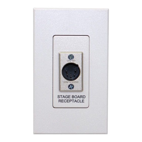
STAGEBOARD
RECEPTACLE
Description
The NT-DMXJ Theatrical Stageboard Receptacle allows a Lutron
Grafik 6000 Lighting Control System to connect to and control a
theatrical stage board. The receptacle features a five-pin XLR style
male jack for connecting Link B* of the Circuit Selector to a
theatrical stage board and provides a standard DMX-512 pinout
(theatrical protocol).
* If DMX is the primary communications protocol, the NT-DMXJ Receptacle
may also connect to Link A of the Circuit selector. Please contact Lutron for
more information regarding this configuration.
Important Notes
1. READ ALL INSTRUCTIONS CAREFULLY BEFORE STARTING
INSTALLATION.
2. This device must be installed by a qualified electrician.
3. Install in accordance with the National Electric Code
applicable local regulations.
4. Turn power OFF at the control panel before installing the
device. Do not connect high-voltage power to low voltage
terminals. Improper wiring can result in personal injury or
damage to the control or to other equipment.
®
0.875 in.
0.285 in.
(22.2 mm)
(7.2 mm)
0.385 in.
(9.8 mm)
and all
®
NT-DMXJ-IN
Theatrical Stageboard Receptacle
(Class 2/PELV Device)
Installation
DANGER! Always turn off the power to the con-
trol panel before doing any work. Failure to do
so can result in serious personal injury and
damage to equipment.
1. Prewiring: The Control Links require special wiring consider-
ations. Refer to the User's Guide and Lutron job drawings for
wiring restrictions and limitations that apply to your specific
project.
2. Turn power OFF.
3. Separate faceplate from faceplate adapter by pulling from the
center of the top of the faceplate. Unscrew faceplate adapter
and set aside.
4. Strip insulation from wires so 3/8" bare wire is exposed. This
device does not get an address and does not count as one of
the 32 controls allowed on the Control Link.
5. Connect wiring as shown on the following page and confirm
all connections.
6. Mount device as shown in the Mounting Diagram using the
mounting screws provided. Screw on faceplate adapter and
snap on faceplate.
7. Restore power to the control panel after the installation of
the system is complete.
Mounting Diagram
Walljack Mounting Screws
Standard U.S. Wallbox
Walljack
Adapter Mounting
Screws
Faceplate Adapter
Faceplate
Advertisement

Related Manuals for Lutron Electronics GRAFIK 6000


Summary of Contents for Lutron Electronics GRAFIK 6000
- Page 1 The NT-DMXJ Theatrical Stageboard Receptacle allows a Lutron device does not get an address and does not count as one of Grafik 6000 Lighting Control System to connect to and control a the 32 controls allowed on the Control Link.
- Page 2 International ++852-2104-7733 National Electrical Code is a registered trademark of National Fire Protection Association. International ++44-(0)207-702-0657 Lutron, and GRAFIK 6000 are registered trademarks, and 2Link is a trademark of Lutron Electronics Co. Inc. Fax: 2104-7633; Fax: (171) 480-6899; © 2003 Lutron Electronics Co., Inc.
Need help?
Do you have a question about the GRAFIK 6000 and is the answer not in the manual?
Questions and answers