
Related Manuals for Oliver 797-48


Summary of Contents for Oliver 797-48
- Page 1 Grand Rapids, Michigan, U.S.A. 49504-5298 USER’S OPERATING AND INSTRUCTION MANUAL MODEL 797-32, 797-48 & 797-PB” BREAD SLICERS 797S20000-C4...
-
Page 2: Table Of Contents
INDEX Section Description Document No. Page No. SAFETY INSTRUCTIONS ------------------------------- 0797S20063 --------------------- 1-1 DESCRIPTION/SPECIFICATIONS -------------------- 0797S20064---------------------- 2-1 Description -------------------------------------------------------------------------------------- 2-1 Specifications----------------------------------------------------------------------------------- 2-1 INSTALLATION INSTRUCTIONS --------------------- 0797S20065 --------------------- 3-1 Removing the Slicer from the Shipping Skid ------------------------------------------- 3-1 Installing Optional Casters ----------------------------------------------------------------- 3-2 OPERATING INSTRUCTIONS ------------------------- 0797S20067 --------------------- 4-1 Adjusting the Gravity Feed Slicer’s Holddown ----------------------------------------- 4-1 Adjusting the Slicer for Product Length -------------------------------------------------- 4-2... -
Page 3: Section Description Document No
INDEX (Continued) REPLACEMENT PARTS SECTION (Continued) Section Description Document No. Page No. BASE/CASTER & FEET --------------------------------- 0797S20072 --------------------- 9-1 Drawing ------------------------------------------------------------------------------------- 9-1 Parts List ----------------------------------------------------------------------------------- 9-2 SLICE PARTS & HOLDDOWN ------------------------ 0797S20073 -------------------- 10-1 Drawing ------------------------------------------------------------------------------------ 10-1 Parts List ---------------------------------------------------------------------------------- 10-2 32 &... - Page 4 INDEX (Continued) REPLACEMENT PARTS SECTION (Continued) Section Description Document No. Page No. THREE PHASE ELECTRICAL ------------------------ 0797S20081 -------------------- 18-1 Wiring Diagram -------------------------------------------------------------------------- 18-1 Drawing ------------------------------------------------------------------------------------ 18-1 Parts Lists --------------------------------------------------------------------------------- 18-2 WARRANTY ------------------------------------------------ GEN 040225 WARRANTY PROCEDURE ---------------------------- GEN 040226 RETURNED PARTS POLICY -------------------------- GEN 040227 REV.
-
Page 5: Safety Instructions
SAFETY INSTRUCTIONS WARNING VARIOUS SAFETY DEVICES AND METHODS OF GUARDING HAVE BEEN PROVIDED ON THIS MACHINE. IT IS ESSENTIAL HOWEVER THAT THE MACHINE OPERATORS AND MAINTENANCE PERSONNEL OBSERVE THE FOLLOWING SAFETY PRECAUTIONS. IMPROPER INSTALLATION, MAINTENANCE, OR OPERATION OF THIS EQUIPMENT COULD CAUSE SERIOUS INJURY OR DEATH. 1. -
Page 6: Description/Specifications
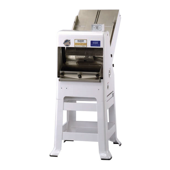
DESCRIPTION/SPECIFICATIONS Description The Oliver Model 797 series of Bread Slicers are of a compact, sturdy, time tested design, which has been used in bakeries worldwide for many years. The machine is easy to operate, with its gravity fed infeed chute, allowing production slicing of product in quantities of up to 600 loaves per hour. - Page 7 Space Requirements: Model 797-48, Space Requirements: Model 797-PB, 0797S20064...
- Page 8 Optional Slice Spacings, (At additional cost). (Specials available -- consult factory). 1/4 (min.), 5/16, 3/8, 5/8, 11/16, 3/4, 13/16, 7/8, 1, 1-1/4 (inches) Shipping Weight, (All Weights are Approximate) 797-32 = 320 lbs. 797-48 = 380 lbs. 797-PB = 450 lbs. 0797S20064...
-
Page 9: Installation Instructions
INSTALLATION INSTRUCTIONS Removing the Slicer from the Shipping Skid After removing the carton you should find the basic slicer completely assembled and strapped to the shipping skid. Cut both straps to free the slicer from the skid. CAUTION THE SLICER IS HEAVY, USE PROPER TECHNIQUE WHEN LIFTING. KEEP BACK STRAIGHT, KNEES BENT, AND LIFT WITH LEGS. - Page 10 CASTER INSTALLATION INSTRUCTIONS Place blocks on the floor approximately (8) and (38) inches from the discharge side of the slicer, see the illustration below. Lower the holddown to its lowest position and tighten the adjustment knob to prevent the outfeed table from swinging out. With one person on each side of the slicer, gently lower the slicer onto the blocks.
- Page 11 On all slicers equipped with either the Power Belt infeed chute option, or a Model 1179S bagger, a counter weight must be attached to the caster brackets on the right hand side of the machine, (as viewed from the outfeed side of the slicer). See the above illustration.
-
Page 12: Operating Instructions
OPERATING INSTRUCTIONS CAUTION ALWAYS USE CARE WHENEVER WORKING NEAR THE CUTTING KNIVES. Adjusting the Gravity Feed Slicer’s Holddown Loosen the holddown adjustment knob. Adjust the holddown so that the product just clears the bottom edge of the holddown as it passes through the cutting knives. Tighten the holddown adjustment knob when the holddown is in the desired location. -
Page 13: Adjusting The Slicer For Product Length
Adjusting the Slicer for Product Length Using a typical product, adjust the infeed chute side guides by applying hand pressure. See the next illustration. Set the side guides approximately 1/8 inch wider than the longest expected product. 0797S20067... -
Page 14: Adjusting The Outfeed Side Guides On A Standard Outfeed Table
Adjusting the Outfeed Side Guides on a Standard Outfeed Table Adjust the side guide extensions so that they are approximately 1/4 inch from the cutting knives. Loosen the outfeed guide adjustment knobs. Adjust the outfeed side guides to align with the infeed guides. See the illustration, which follows. Once satisfied with the location re-tighten the side guide adjustment knobs. -
Page 15: Operating A Gravity Feed Slicer
Operating a Gravity Feed Slicer Once the slicer has been properly adjusted for product clearance, the infeed chute may be loaded with the product to be sliced. Flipping the starting switch to the ON position will begin operation. Remove each sliced product from the discharge table as it is sliced. NOTE THE GRAVITY FEED SLICER’S OPTIMUM OPERATING EFFICIENCY WILL BE MAINTAINED BY ENSURING THAT THE INFEED CHUTE IS KEPT... - Page 16 Operating the Gravity Feed’s Lever Actuated Last Loaf Pusher (continued) CAUTION THE KNIVES ARE EXTREMELY SHARP. DO NOT TOUCH MOVING OR STATIONARY KNIVES. Once the last loaf pusher has fed the product into the cutting knives as far as it can, it may be necessary to pull the product the rest of the way through the knives by hand.
-
Page 17: Troubleshooting
TROUBLESHOOTING WARNING ALWAYS DISCONNECT THE SLICER FROM THE POWER SUPPLY BEFORE ATTEMPTING ANY TYPE OF MAINTENANCE TASK, INCLUDING TROUBLESHOOTING. The Slicer Will Not Start (Motor Is Not Humming) • The machine is not plugged in. • There is no power at the outlet. (Check by plugging in a small working appliance, like a lamp. -
Page 18: Bread Slices Vary In Thickness
Bread Slices Vary in Thickness • The blade frames are out of adjustment. (See the “Maintenance” section of this manual under “Adjusting the Blade Frames When Slices Vary in Thickness” on how to correct this problem.) The Blade Frames Are Knocking •... -
Page 19: Maintenance
MAINTENANCE WARNING ALWAYS DISCONNECT THE SLICER FROM THE POWER SUPPLY BEFORE ATTEMPTING ANY TYPE OF MAINTENANCE TASK. Cleaning Use a mild detergent solution to clean all exterior surfaces and empty the crumb tray daily or more often if necessary. Periodically swing out the discharge table to allow access to the drive area of the machine, then brush, blow, (if compressed air is available), or wipe all foreign material from all surfaces, especially from moving parts. -
Page 20: Removing The Blade Frames
Removing the Blade Frames WARNING ALWAYS DISCONNECT THE SLICER FROM THE POWER SUPPLY BEFORE ATTEMPTING ANY TYPE OF MAINTENANCE TASK. Swing out the discharge table from the slicer. See the next illustration. Always start by removing the discharge side blade frame first. Both blade frames should be removed from the discharge side of the machine, (see the note below). - Page 21 Removing the Blade Frames (Continued) NOTE NEVER LOOSEN THE NUTS ON THE ECCENTRIC PINS OR ATTEMPT TO REMOVE THEM TO AID IN REMOVING THE BLADE FRAMES. Start by pulling the hairpin clip from the eccentric pin, located at the top of each blade frame, see illustration below, then slide the top link toward the eccentric pin’s mounting plate.
- Page 22 Removing the Blade Frames (Continued) CAUTION THE BLADES ARE EXTREMELY SHARP. ALWAYS HANDLE BLADE FRAMES WITH CARE. The blade frame can now be carefully lifted from the slicer. See below. Removal of the infeed side blade frame is accomplished in a similar fashion. However the chute guard must first be removed by removing the four knobs which hold it in place this will allow access to the locking cams.
-
Page 23: Changing The Blades
Changing the Blades WARNING ALWAYS DISCONNECT THE SLICER FROM THE POWER SUPPLY BEFORE ATTEMPTING ANY TYPE OF MAINTENANCE TASK. CAUTION THE BLADES ARE EXTREMELY SHARP. ALWAYS HANDLE THEM WITH CARE. NOTE DO NOT INTERCHANGE THE TWO BLADE FRAMES. REPLACE THE BLADE FRAME TO THE SAME SIDE OF THE MACHINE AS IT WAS TAKEN FROM NOTE WHEN CHANGING BLADES FIRST NOTE THE DIRECTION THE SHARPENED... - Page 24 Changing the Blades (Continued) The new knife can be installed by reversing the removal procedure. A paper clip can be used to hold the knife in position on the lower pin to ease installation. See the illustration below. NOTE WHEN REPLACING ALL THE KNIVES, ALWAYS REMOVE THE CENTER KNIVES FIRST AND WORK TOWARD THE ENDS.
-
Page 25: Tightening The Belt
Tightening the Belt WARNING ALWAYS DISCONNECT THE SLICER FROM THE POWER SUPPLY BEFORE ATTEMPTING ANY TYPE OF MAINTENANCE TASK. CAUTION OVER-TIGHTENING THE DRIVE BELT MAY CAUSE BEARING OR MOTOR FAILURE. Remove the crumb tray from the slicer and swing out the discharge table. See the illustration below. - Page 26 Tightening the Belt (Continued) Loosen the lockbolt located below the belt adjustment mechanism. See the next illustration. Locate the adjustment bolt below the belt and turn it counter clockwise with a wrench to increase tension on the belt or clockwise to reduce tension on the belt. The drive belt should be just tight enough that, using moderate finger pressure, it would deflect about 3/8 of an inch when pressed midway between the motor drive pulley and the driven pulley.
-
Page 27: Replacing The Belt
Replacing the Belt WARNING ALWAYS DISCONNECT THE SLICER FROM THE POWER SUPPLY BEFORE ATTEMPTING ANY TYPE OF MAINTENANCE TASK. Referring to the “Tightening the Belt” section above, remove the crumb tray, swing out the discharge table, and reduce the tension on the belt by turning the adjusting bolt on the tightening mechanism clockwise until the belt can be slipped off from the motor pulley. -
Page 28: Adjusting The Blade Frames When Slices Vary In Thickness
Adjusting the Blade Frames When Slices Vary in Thickness WARNING ALWAYS DISCONNECT THE SLICER FROM THE POWER SUPPLY BEFORE ATTEMPTING ANY TYPE OF MAINTENANCE TASK. Swing out the discharge table of the slicer. Loosen, but do not remove the two capscrews which secure the blade frame to the swing shaft, (see below). -
Page 29: Adjusting The Clearance Between The Blade Frames
Adjusting the Clearance Between the Blade Frames WARNING ALWAYS DISCONNECT THE SLICER FROM THE POWER SUPPLY BEFORE ATTEMPTING ANY TYPE OF MAINTENANCE TASK. The distance between the blade frames is adjusted by rotating the eccentric pins located above the blade frames. Two wrenches are used to do this. One wrench is used to keep the eccentric pin from rotating while the second is used to loosen the lock nut on the end of the pin. -
Page 30: Recommended Spare Parts
Stud-Driven Pulley 6904-6001 Gasket-Driven Pulley 0797-0071-3 Rod-Connecting 0797-0057-2 Stud-Swing 5220-4040 Bearing-Rocker Shaft 5220-0020 Bearing-Swing Shaft 6301-3609* Motor-1/2 HP, 1-60-115/230 0797-0029-1 Knife-Type A As Req’d. *For Other Electrics Contact the Factory For Service Parts Call Oliver Products @ 800-253-3893 Rev. 8/2604 0797S20070... -
Page 31: Main Frame & Rocker
MAIN FRAME/ROCKER ASSEMBLY Rev. 9/16/04 0797S20071... - Page 32 TRAY- CRUMB (W/O BASE) 0797-0054 TRAY-EXTRA CAP. CRUMB (W/BASE) 0797-3079 ROCKER 0797-0047-2 SHAFT-SWING 0797-0060 COLLAR-HOLD DOWN 0797-0031-001 COLLAR-LOCATING 0797-0031-1 SCREW-SOCKET SET 3/8-16 X ¼ 5842-6156 BEARING-BALL 5220-0020 CAP-BALL BEARING 4090-0232-0004 FOR SERVICE PARTS CALL OLIVER PRODUCTS @ 800-253-3893 Rev. 9/16/04 0797S20071...
- Page 33 BASE/CASTER& FEET ASSEMBLY 0797S20072...
-
Page 34: Drawing
BASE/CASTER PARTS LIST ITEM NO PART DESCRIPTION PART NUMBER BASE-16” CASTER 0797-3068 152* FOOT-RUBBER (UNITS W/O BASE) 0797-3257 CASTER-3” RIGID 5902-2363 CASTER-3” SWIVEL 5902-2364 * Not Shown on Drawing FOR SERVICE PARTS CALL OLIVER PRODUCTS @ 800-253-3893 0797S20072... - Page 35 SLICE PARTS/HOLDDOWN ASSEMBLY 0797S20073 10-1...
- Page 36 0797-3012 HOLDDOWN 0797-0358-201 KNOB 5911-7001 601* FRAME-BLADE 0797-0300-5XX KNIFE-TYPE A 0797-0029-1 PIN-BLADE FRAME 0797-0059-2 609* GUIDE-KNIFE 0797-0092-0XX 612** TOOL-BLADE CHANGING 0797-0183 Specify Slice Thickness Not Shown on Drawing FOR SERVICE PARTS CALL OLIVER PRODUCTS @ 800-253-3893 Rev. 8/26/04 0797S20073 10-2...
- Page 37 32 & 48 INCH GRAVITY INFEED CHUTE ASSEMBLY 0797S20074 11-1...
- Page 38 COLLAR-3/4” SET 5806-7012 GUIDE-32” SIDE 0797-3005-002 GUIDE-48” SIDE 0797-3010-001 BUSHING-SNAP 5765-1058 PIN-SIDE GUIDE 0797-3011-002 WASHER-HORSESHOE 0793-0084 SPRING-COMPRESSION 7012-3102 GUARD-CHUTE 0797-0915-002 GUARD-CHUTE CROTCH 0797-0947 SHAFT-PUSHER CROSS 0797-2076-002 HUB-PUSHER LEVER 0797-3070-001 LEVER-PUSHER 0711-0024 FOR SERVICE PARTS CALL OLIVER PRODUCTS @ 800-253-3893 0797S20074 11-2...
- Page 39 48 INCH POWERBELT INFEED ASSEMBLY 0797S20075 12-1...
- Page 40 0797-3010-001 WASHER-BRASS HORSESHOE 0793-0084 PIN-SIDE GUIDE 0797-3011-002 BUSHING-SNAP 5765-1058 WASHER-NYLON FLAT 5851-8120 SPRING-COMPRESSION 7012-3102 BELT-CONVEYOR 5600-9468 PAN-BOTTOM 0797-3026 378* WEIGHT-COUNTER 0797-3080-001 379* TOOL-KNIFE (POWERBELT) 0797-0183-004 * Not Shown on Drawing FOR SERVICE PARTS CALL OLIVER PRODUCTS @ 800-253-3893 0797S20075 12-2...
- Page 41 DRIVEN PULLEY ASSEMBLY REV. 2/9/04 0797S20076 13-1...
- Page 42 DRIVEN PULLEY PARTS LIST ITEM NO PART DESCRIPTION PART NUMBER PULLEY (32” CHUTES) 0797-0049-103 PULLEY (48” CHUTES) 0797-3370 STUD-SWING 0797-0057-2 RING-RETAINING 5840-2825 STUD 0797-0058-1 ROD-CONNECTING 0797-0071-3 FOR SERVICE PARTS CALL OLIVER PRODUCTS @ 800-253-3893 REV. 2/9/04 0797S20076 13-2...
- Page 43 STANDARD OUTFEED ASSEMBLY 0797S20077 14-1...
- Page 44 BRACKET- RH OUTFEED TABLE 0797-3013-0001 BRACKET- LH OUTFEED TABLE 0797-3013-0002 CAP-NEOPRENE 5106-8920 STOP-BREAD 0797-0141 KNOB 5911-7000 GUIDE-BREAD 0797-0284 EXTENSION-RH GUIDE 0797-0285-0001 EXTENSION-LH GUIDE 0797-0285-0002 420* LIP-TABLE 0797-3001-0XX Specify Slice Thickness FOR SERVICE PARTS CALL OLIVER PRODUCTS @ 800-253-3893 0797S20077 14-2...
- Page 45 BAGGER OUTFEED ASSEMBLY 0797S20078 15-1...
- Page 46 BRACKET-CASE MOUNTING 1179-0011 BRACKET-CASE 1179-0012 TABLE-OUTFEED 1179-0008 418* LIP-TABLE 0797-3001-0XX GUIDE-SIDE RH 1179-0009-0001 GUIDE-SIDE LH 1179-0009-0002 WASHER-NYLON 5851-8120 SPRING-COMPRESSION 7013-2100 428** WEIGHT-COUNTER 0797-3080-001 Specify Slice Thickness Not Shown on Drawing FOR SERVICE PARTS CALL OLIVER PRODUCTS @ 800-253-3893 0797S20078 15-2...
- Page 47 CURVED OUTFEED ASSEMBLY 0797S20079 16-1...
- Page 48 TABLE-CURVED 0797-3029-1 411* LIP-TABLE 0797-3001-0XX GUIDE-SIDE RH 0797-3030-1001 GUIDE-SIDE LH 0797-3030-1002 COLLAR-FILLING 4130-0708-0003 NUT-ACORN ¼-20 5832-0590 WASHER-NYLON 5851-8120 WASHER-STAINLESS STEEL 5851-9304 SPRING-COMPRESSION 7013-2100 EXTENSION-RH 0797-0285-0001 EXTENSION-LH 0797-0285-0002 Specify Slice Thickness FOR SERVICE PARTS CALL OLIVER PRODUCTS @ 800-253-3893 0797S20079 16-2...
- Page 49 SINGLE PHASE ELECTRICAL Wiring Diagram (Single Phase) Single Phase Electrical Assembly Drawing 0797S20080 17-1...
-
Page 50: Parts List
BELT-V (4L36-1/2) (32” CHUTES) 5601-1966 BELT-V (XDV48-380) (48” CHUTES) 5601-1969 PULLEY-MOTOR (32” CHUTES) 4575-7104-2002 PULLEY-MOTOR (48” CHUTES) 4575-7104-2005 MOTOR 6301-3940 COVER-SWITCH ENCLOSURE 0797-3394-001 SWITCH-STARTER 5709-1125 COVER-RECEPTACLE ENCLOSURE 0797-3385 RECEPTACLE-220/230 VAC 5769-0523 For Service Parts Call Oliver Products @ 800-253-3893 0797S20080 17-2... - Page 51 THREE PHASE ELECTRICAL Wiring Diagram (Three Phase) Three Phase Electrical Assembly Drawing 0797S20081 18-1...
- Page 52 ITEM NO PART DESCRIPTION PART NUMBER STARTER 5709-3034 CORD-POWER 0797-3426 BELT-V (4L36-1/2) (32” CHUTES) 5601-1966 BELT-V (XDV48-380) (48” CHUTES) 5601-1969 PULLEY-MOTOR (32” CHUTES) 4575-7104-2002 PULLEY-MOTOR (48” CHUTES) 4575-7104-2005 MOTOR 6301-3975 For Service Parts Call Oliver Products @ 800-253-3893 0797S20081 18-2...
- Page 53 THIS PAGE WAS INTENTIONALLY LEFT BLANK. GEN020319...
- Page 54 Oliver) proves to be defective (as defined below) within one year after shipment, and if Buyer returns the defective part to Oliver within one year, Freight Prepaid to Oliver’s plant in Grand Rapids, MI, then Oliver, shall, at Oliver’s option, either repair or replace the defective part, at Oliver’s expense.
- Page 55 THIS PAGE WAS INTENTIONALLY LEFT BLANK. GEN020319...
- Page 56 4. The service dealer will then complete an invoice and send it to the Customer Service Department at Oliver Products Company. 5. The Customer Service Manager of Oliver Products Company will review the invoice and returned parts, if applicable, and approve for payment.
- Page 57 THIS PAGE WAS INTENTIONALLY LEFT BLANK. GEN020319...
- Page 58 This policy applies to all parts returned to the factory whether for warranted credit, replacement, repair or re-stocking. Oliver Products Company requires that the customer obtain a Return Material Authorization (RMA) number before returning any part. This number should appear on the shipping label and inside the shipping carton as well.
Need help?
Do you have a question about the 797-48 and is the answer not in the manual?
Questions and answers