
Related Manuals for RADWAG WTC 200


Summary of Contents for RADWAG WTC 200
-
Page 1: User Manual
WTC 200 Precision Scale WTC 600 Precision Scale WTC 2000 Precision Scale WTC 3000 Precision Scale USER MANUAL ITKU-95-04-06-18-EN... - Page 2 JUNE 2018 - 2 -...
-
Page 3: Table Of Contents
CONTENTS 1. GENERAL INFORMATION ........................5 2. PRECAUTIONS ............................5 2.1. Operation ............................5 2.2. Battery Power Supply ........................5 3. WARRANTY CONDITIONS ........................6 4. DESIGN ..............................7 4.1. Dimensions ............................7 4.2. Connectors Arrangement......................... 8 4.3. Connectors Description........................8 5. - Page 4 15.2. Printer............................28 15.2.1. Printer Port ........................28 15.3. Additional Display......................... 28 15.3.1. Additional Display Port ..................... 28 16. PRINTOUTS ............................28 16.1. Adjustment Report........................29 16.2. GLP Printout..........................29 17. MISCELLANEOUS PARAMETERS..................... 30 17.1. Backlight............................30 17.2. 'Beep' Sound ..........................31 17.3.
-
Page 5: General Information
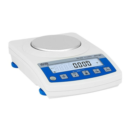
1. GENERAL INFORMATION WTC precision scale enables fast and accurate mass measurements under laboratory conditions. The weighing pan, made of stainless steel and equipped with an anti-draft shield, is an integral part of the WTC scale. Due to a backlit LCD display the measurement result is clearly visible. -
Page 6: Warranty Conditions
Pb = lead, Cd = cadmium, Hg = mercury. 3. WARRANTY CONDITIONS A. RADWAG feels obliged to repair or exchange all elements that appear to be faulty by production or by construction. B. Defining defects of unclear origin and means of their elimination can only be realized with assistance of manufacturer and user representatives. -
Page 7: Design
4. DESIGN 4.1. Dimensions Figure 1. Dimensions of WTC 200 scale Figure 2. Dimensions of WTC 600, WTC 2000, WTC 3000 scale - 7 -... -
Page 8: Connectors Arrangement
4.2. Connectors Arrangement Figure 3. Connectors view DC IN – power supply socket RS232 - RS232 connector USB 2 - USB „device” connector USB 1 - USB „host” connector 4.3. Connectors Description Pin2 – RxD Pin3 – TxD RS 232 connector Pin4 –... -
Page 9: Start-Up And Operation
6. START-UP AND OPERATION 6.1. Levelling To level the weighing instrument turn its feet. Keep turning the feet until the air bubble takes central position: 6.2. Connecting the Scale to the Mains The weighing device can be connected to the mains only with a power supply that comes standard with the particular model. -
Page 10: Battery Charge Status
6.4. Battery Charge Status The scale of standard design is equipped with an internal battery. Battery state is signalled by pictogram, the pictogram is displayed in the top bar of the display. Meaning pictogram display mode No pictogram Battery charged. Regular scale operation. Too low battery charge (the scale is about to shut Pictogram displayed continuously down). -
Page 11: Cleaning Stainless Steel Components
7.2. Cleaning Stainless Steel Components Avoid using cleansers containing any corrosive chemicals, e.g. bleach (including chlorine). Do not use cleansers containing abrasive substances. Always remove the dirt using microfiber cloth to avoid damage of protective coating. In case of a daily maintenance: 1. -
Page 12: Program Structure
Upon pressing keys combination, functions of given keys change. Detailed information concerning use of keys combination is to be found further down this manual. 10. PROGRAM STRUCTURE Program menu is divided into function groups. Function group is a group of interrelated parameters. -
Page 13: Return To The Weighing Mode
Press to check battery/accumulator state. Press to view date/time. Press to: • scroll the menu down, • change current parameter value. Press to: • enter given submenu, • modify given parameter. Press to confirm modification. Press to: • exit, function remains unmodified, •... -
Page 14: Zeroing
Load the weighing pan steadily avoiding mechanical shocks. Place weighed loads centrally on weighing (eccentricity errors are specified by EN 45501 standard, point 3.6.2.). Do not apply concentrated force (total load in one point). Avoid side loading, in particular side shocks. 11.2. -
Page 15: Taring
11.3. Taring To determine net weight value, load the weighing pan with a packaging, wait for a stable indication and press key. Zero indication and the following pictograms are displayed: Net and . The weighing device has been tarred. Upon loading, net mass is displayed. Taring can be carried out repeatedly within the whole weighing range. -
Page 16: Units
Switching from weighing with the accuracy of the II weighing range to weighing with the accuracy of the I weighing range takes place automatically upon unloading the weighing pan and returning to AUTOZERO pictogram/marker is displayed). II weighing range pictogram/marker gets blank. 11.6. -
Page 17: Temporary Unit
11.6.2. Temporary Unit Temporary unit runs from the moment it is set to the scale shut-down and restart. Procedure: • Enter <P9.Unit / 9.2.Unin> submenu. • Press key, available units are displayed successively one by one. Options in case when the main unit is [kg]: •... -
Page 18: External Adjustment
Adjustment types: • external adjustment, <1.1.CA-E>, performed using an external weight of declared mass, i.e. mass that cannot be modified, • user adjustment, <1.2.CA-u>, performed using an external weight of mass of any value comprised within the weighing range, however not lower than 30% of the maximum capacity value. -
Page 19: Adjustment Report
• Remove the load from the weighing pan and press key. • Mass of an empty weighing pan is determined, this is signalled with display of 'dash', < - >. Next, text <LoAd> (load weight) and mass value that is to be loaded, e.g. 100 g, are displayed. •... -
Page 20: Value Release
13.2. Value Release Enter this parameter to adjust rate of stabilisation of the measurement result. Depending on the selected option, weighing time is either shorter or longer. Procedure: • Enter <P2.rEAd / 2.2.APPr> submenu. • Press key, available values are displayed successively one by one: F_P - fast and reliable, PrEc –... -
Page 21: Tare Function
• Press key to confirm, next go to the home screen. 13.5. Tare Function 'Tare' function has been designed to enable setup of appropriate parameters for tare operation. Procedure: • Enter <P2.rEAd / 2.5.tArE> submenu. • Press key, available values are displayed successively one by one: Regular tare mode. -
Page 22: Tare: Values Memory
• Press key to confirm, next go to the home screen. 13.7. Tare: Values Memory It is possible to store 10 tare values in scale memory. 13.7.1. Entering Tare Value to the Weighing Device Memory • Enter <P2.rEAd / 2.7.tArn> submenu, name of tare no. 1 from tares database is displayed (<tArE 0>), to select a different record press key. -
Page 23: Last Digit
The tare value acquired from the weighing device memory is not remembered upon the weighing device restart. 13.8. Last Digit Function designed to disable display of the last weighing indication digit, this results with less accurate measurement. Procedure: • Enter <P2.rEAd / 2.8.LdiG> submenu. •... -
Page 24: Usb A Port
COM port in a computer. To carry out this procedure, you need a respective driver installer which either downloaded from www.radwag.pl website or taken from a CD with manuals: RADWAG USB DRIVER x.x.x.exe. Procedure: 1. Run the driver installer and follow the commands. Select language version and press button „OK”... - Page 25 Select directory press „Next” button. In order to start installation process press „Next” button. Connect scale computer, use 1.8-meter long USB A/B cable maximum (in case already connected scale, necessary disconnect it and reconnect using USB cable). Respective message displayed, press button confirmation.
-
Page 26: Peripheral Devices
Press „Finish” button. Connect the scale to a computer again, use 1.8-meter long USB A/B cable maximum. Respective message box is displayed, press OK button for confirmation. „COM ports Screen” automatically displays number of installed COM port. In this very case it is COM8. -
Page 27: Computer
15.1. Computer <5.1.PC> submenu allows you to: • select port to which the computer is connected, • enable/disable continuous transmission, • set frequency of printouts for continuous transmission. 15.1.1. Computer Port • Enter <5.1.PC / 5.1.1.Prt> submenu. • Press key, parameter values are displayed successively one by one: nonE –... -
Page 28: Printer
15.2. Printer 15.2.1. Printer Port Parameter enabling you to select port to which data is to be sent upon pressing key. Procedure: • Enter <5.2.Prtr / 5.2.1.Prt> submenu. • Press key, parameter values are displayed successively one by one: None port selected. nonE Port RS232. -
Page 29: Adjustment Report
16.1. Adjustment Report <P6.1.CrEP> is a group of parameters allowing you to declare variables that are to be printed on an adjustment report printout. Each variable features accessibility attribute: YES – print, no – do not print. Adjustment report is automatically generated at the end of each adjustment process. -
Page 30: Miscellaneous Parameters
Variables list: Name Description 6.2.1. Performed weighing date. 6.2.2. Performed weighing time. 6.2.3. Net weight value of performed weighing in basic measuring unit. 6.2.4. Tare weight value in the current unit. 6.2.5. Gross weight value in the current unit. 6.2.6. Current weighing result (net weight) in a current unit. -
Page 31: Beep' Sound
Backlight off. nonE Display brightness low limit value in [%]. Display brightness high limit value in [%]. • Press key to confirm, next go to the home screen. 17.2. 'Beep' Sound Parameter allowing you to enable/disable sound signal informing the operator about pressing panel key(s). -
Page 32: Default User Settings
Procedure: • Enter <P7.Othr> submenu and change the settings. Refer to the below table: Parameter Description Enter this parameter to set current date, where the date format is <7.4.SdAt> YYYY.MM.DD*. Enter this parameter to set current time, where the time format is <7.5.Stnn>... -
Page 33: Working Modes - General Information
19. WORKING MODES – General Information The scale features the following working modes: • Weighing, • Parts counting, • +/- control, • Percent weighing %, • Peak Hold, • Totalizing. 19.1. Running Working Mode • Go to home screen, press key, name of the first available working mode is displayed. -
Page 34: Working Mode Accessibility
The table presents special function number and name for each of the working modes. Remaining specific functions referring directly to a given working mode are described further down this user manual. 19.2.1. Working Mode Accessibility To enable/disable given working mode, press key. -
Page 35: Automatic Printout Time Interval
• Press key to confirm, next go to the home screen. 19.2.3. Automatic Printout Time Interval Parameter enabling you to set frequency of automatic printout. Printout interval is set in minutes with 1 [min] accuracy within 1 [min] - 1440 [min] range. Procedure: •... -
Page 36: Working Mode - Parts Counting
21. WORKING MODE – PARTS COUNTING Parts Counting is a working mode enabling you to determine quantity of small pieces of the same mass, which determination is done on the basis of mass of sample piece (single part), and where the sample piece mass (single part mass) is determined using the weighing device. -
Page 37: Setting Sample Mass By Determining Mass Of A Single Part
• Enter respective value and press key to confirm, home screen is displayed automatically along with quantity of parts loaded onto the weighing pan (pcs). If the value of entered single part mass is greater than max capacity value, then message <Err Hi> is displayed. 21.3. -
Page 38: Working Mode - +/- Control
In the course of parts quantity determination before confirming the declared quantity value it is necessary to wait for a stable measurement, 22. WORKING MODE – +/- CONTROL +/- control is a working mode enabling you to enter checkweighing thresholds values (Min, Max). -
Page 39: Working Mode - Percent Weighing
If the entered high threshold value (Max) is greater than the maximum capacity value, <Err Hi> error is displayed. 23. WORKING MODE - PERCENT WEIGHING Percent weighing is a working mode enabling you to compare measured load mass with the reference sample mass. The result is expressed in [%]. Reference sample mass can be either determined by weighing or entered to weighing device memory by an operator. -
Page 40: Reference Sample Mass Determined By Weighing
23.2. Reference Sample Mass Determined by Weighing • Enter <3.4.dEu / 3.4.2.UUt> submenu, set < > value. • Enter <dEu> working mode (Percent weighing), first, text <LoAd> is displayed for 1 second, then the weighing window. • Load the weighing pan with the reference sample. When the indication is stable ( pictogram is displayed), press key to confirm the mass. -
Page 41: Working Mode - Totalizing
• Enter <toP> working mode (Peak Hold). From now on the scale registers and holds every single weighing which is above the Lo threshold, and which is higher than the result of the previous peak hold. Snapped peak hold value is signalled by <Max> pictogram displayed at the top of the screen. -
Page 42: Import / Export
• Load the weighing pan with the ingredient no.2, wait for a stable weighing result and press key. • Total mass value of ingredient no. 1 and 2 is displayed, now the „▲” pictogram is displayed continuously. • In order to finish the process, press key, text <Prnt?>... -
Page 43: Weighing Records Export
These files can be read using ALIBI Reader, PC software designed by RADWAG. You can download the software from RADWAG website: www.radwag.pl. -
Page 44: Communication Protocol
27.1. General Information A. A character based communication protocol, scale - indicator, is designed for establishing communication between a RADWAG scale and a peripheral device via RS232C serial interface. B. The protocol consists of commands sent from a peripheral device to the scale and responses from the scale. -
Page 45: Response Format
Unlock scale keypad Give scale serial number Send all implemented commands Each command must end with CR LF characters. 27.3. Response Format On receipt of a command, the indicator responds as follows: command understood and in progress. XX_A CR LF command carried out (appears only after the XX_A command). - Page 46 27.4.2. Tare Scale Format: T CR LF Response options: - command understood and in progress. T_A CR LF - command carried out. T_D CR LF - command understood and in progress. T_A CR LF - command understood but taring range is exceeded. T_v CR LF - command understood and in progress.
- Page 47 27.4.5. Send Stable Measurement Result in Basic Measuring Unit Format: S CR LF Response options: - command understood and in progress. S_A CR LF - time limit exceeded while waiting for stable measurement result. S_E CR LF - command understood but not accessible at this moment. S_I CR LF - command understood and in progress.
- Page 48 27.4.7. Send Stable Measurement Result in Current Measuring Unit Format: SU CR LF Response options: - command understood and in progress. SU_A CR LF - time limit exceeded while waiting for stable measurement result. SU_E CR LF - command understood but not accessible at this moment. SU_I CR LF - command understood and in progress.
- Page 49 27.4.9. Switch on Continuous Transmission in Basic Measuring Unit Format: C1 CR LF Response options: - command understood but not accessible at this moment. C1_I CR LF - command understood and in progress. C1_A CR LF - response: mass value in basic measuring unit. MASS FRAME Response format: 7-15...
- Page 50 - command understood but not accessible at this moment. CU0_I CR LF - command understood and carried out. CU0_A CR LF 27.4.13. Lock Scale Keypad Format: K1 CR LF Response options: - command understood but not accessible at this moment. K1_I CR LF - command carried out.
-
Page 51: Manual Printout / Automatic Printout
27.5. Manual Printout / Automatic Printout It is possible to generate printouts both manually and automatically. • Manual printout is generated for stable weighing result. Load the platform, wait for a stable result and press key. • Automatic printout is generated for stable weighing result. Load the platform, wait for a stable result. -
Page 52: Continuous Transmission
27.6. Continuous Transmission For continuous transmission mode the scale provides option of mass measurement printout in basic unit and in additional unit. The mode can be activated with command sent via computer, or by setting respective parameter values on the scale. Format of frame sent when <5.1.2.Cnt>... -
Page 53: Diagrams Of Connection Cables
28. DIAGRAMS OF CONNECTION CABLES scale – computer cable scale - printer cable (EPSON) - 53 -... -
Page 54: Error Messages
29. ERROR MESSAGES - Value beyond zero range. - E r r 2 - - Value beyond tare range. - E r r 3 - - Adjustment weight or start mass out of range (±1% for adjustment weight, ±10 - E r r 4 - for start mass). - Page 55 - 55 -...
Need help?
Do you have a question about the WTC 200 and is the answer not in the manual?
Questions and answers