Table of Contents
Advertisement
Quick Links
Quick Installation Guide
00825-0100-4803, Rev BA
April 2011
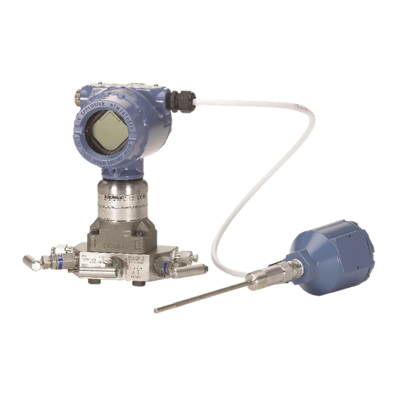
Rosemount 3051S MultiVariable
Transmitter
Rosemount 3051SF Series Flowmeter
MultiVariable Transmitter
Step 1: Mount the Transmitter
Step 2: Consider Housing Rotation
Step 3: Set Switches
Step 4: Connect Wiring and Power Up
Step 5: Flow Configuration
Step 6: Verify Device Configuration
Step 7: Trim the Transmitter
Product Certifications
¢00825-0100-4801J¤
www.rosemount.com
Rosemount 3051SMV
Start
End
™
Advertisement
Table of Contents

Related Manuals for Rosemount 3051SMV


Summary of Contents for Rosemount 3051SMV
- Page 1 00825-0100-4803, Rev BA Rosemount 3051SMV April 2011 ™ Rosemount 3051S MultiVariable Transmitter Rosemount 3051SF Series Flowmeter MultiVariable Transmitter Start Step 1: Mount the Transmitter Step 2: Consider Housing Rotation Step 3: Set Switches Step 4: Connect Wiring and Power Up...
- Page 2 Quick Installation Guide 00825-0100-4803, Rev BA Rosemount 3051SMV April 2011 © 2011 Rosemount Inc. All rights reserved. All marks property of owner. Rosemount and the Rosemount logotype are registered trademarks of Rosemount Inc. Rosemount Inc. Emerson Process Management 8200 Market Boulevard GmbH &...
- Page 3 Quick Installation Guide 00825-0100-4803, Rev BA Rosemount 3051SMV April 2011 1: M OUNT THE RANSMITTER Liquid Flow Applications 1. Place taps to the side of the line. 2. Mount beside or below the taps. 3. Mount the transmitter so that the drain/vent valves are oriented upward.
- Page 4 Quick Installation Guide 00825-0100-4803, Rev BA Rosemount 3051SMV April 2011 Mounting Brackets ™ Coplanar Flange Panel Mount Pipe Mount Traditional Flange Panel Mount Pipe Mount...
- Page 5 Quick Installation Guide 00825-0100-4803, Rev BA Rosemount 3051SMV April 2011 Bolting Considerations If the transmitter installation requires assembly of a process flange, manifold, or flange adaptors, follow these assembly guidelines to ensure a tight seal for optimal performance characteristics of the transmitter.
- Page 6 Quick Installation Guide 00825-0100-4803, Rev BA Rosemount 3051SMV April 2011 Bolts are typically carbon steel or stainless steel. Confirm the material by viewing the markings on the head of the bolt and referencing Figure 3. If bolt material is not shown in Figure 3, contact the local Emerson Process Management representative for more information.
- Page 7 The two flange adapters are distinguished by unique O-ring grooves. Only use the O-ring that is designed for its specific flange adapter, as shown below. Rosemount 3051S / 3051 / 2051 / 3095 Flange Adapter O-ring...
- Page 8 Quick Installation Guide 00825-0100-4803, Rev BA Rosemount 3051SMV April 2011 2: C ONSIDER OUSING OTATION To improve field access to wiring or to Figure 4. Transmitter Housing Set Screw better view the optional LCD display: 1. Loosen the housing rotation set screw.
- Page 9 Quick Installation Guide 00825-0100-4803, Rev BA Rosemount 3051SMV April 2011 3: S WITCHES The transmitter’s default configuration sets the alarm condition to high (HI) and the security to off. 1. If the transmitter is installed, secure the loop and remove power.
- Page 10 Quick Installation Guide 00825-0100-4803, Rev BA Rosemount 3051SMV April 2011 4: C ONNECT IRING AND OWER NOTE Do not connect the power across the test terminals. Power could damage the test diode in the test connection. Twisted pairs yield best results. Use 24 AWG to 14 AWG wire and do not exceed 5,000 feet (1500 meters).
- Page 11 GE or GM, refer to the cordset manufacturer’s installation instructions for wiring details. For FM Intrinsically Safe, Division 2 hazardous locations, install in accordance with Rosemount drawing 03151-1009 to maintain outdoor rating (NEMA 4X and IP66.) See Appendix B of the 3051S MultiVariable transmitter reference manual (00809-0100-4803).
-
Page 12: Power Supply
Quick Installation Guide 00825-0100-4803, Rev BA Rosemount 3051SMV April 2011 Power Supply The dc power supply should provide power with less than two percent ripple. The total resistance load is the sum of the resistance of the signal leads and the load resistance of the controller, indicator, intrinsic safety barriers, and related components. - Page 13 Quick Installation Guide 00825-0100-4803, Rev BA Rosemount 3051SMV April 2011 Install Optional Process Temperature Input (Pt 100 RTD Sensor) NOTE To meet ATEX/IECEx Flameproof certification, only ATEX/IECEx Flameproof Cables (Temperature Input Code C30, C32, C33, or C34) may be used.
- Page 14 5: F ONFIGURATION Engineering Assistant 6.1 or Later The 3051SMV Engineering Assistant 6.1 or later is PC-based software that performs configuration, maintenance, diagnostic functions, and serves as the primary communication interface to the 3051S MultiVariable transmitter with the Fully Compensated Mass and Energy Flow Feature Board.
- Page 15 Quick Installation Guide 00825-0100-4803, Rev BA Rosemount 3051SMV April 2011 Installing 3051SMV Engineering Assistant 6.1 or Later 1. Uninstall any existing versions of Engineering Assistant 6 currently installed on the PC. 2. Insert the new Engineering Assistant disk into the CD-ROM.
- Page 16 4. On the side of the transmitter marked “Field Terminals,” connect the modem mini-grabbers to the two terminals marked “PWR/COMM.” 5. Launch the 3051SMV Engineering Assistant software. For more information on launching software, see “Launching Engineering Assistant 6.1 or Later” on page 20.
- Page 17 Rosemount 3051SMV April 2011 Flow Configuration The 3051SMV Engineering Assistant is designed to guide the user through the setup of the flow configuration for a 3051S MultiVariable transmitter. The flow configuration screens allow the user to specify the fluid, operating conditions, and information about the primary element, including inside pipe diameter.
- Page 18 Quick Installation Guide 00825-0100-4803, Rev BA Rosemount 3051SMV April 2011 Basic Navigation Overview Figure 10. Engineering Assistant Basic Navigation Overview The Engineering Assistant software can be navigated in a variety of ways. The numbers below correspond to the numbers shown in Figure 10.
- Page 19 Quick Installation Guide 00825-0100-4803, Rev BA Rosemount 3051SMV April 2011 2. The Reset button will return each field within all of the flow configuration tabs (Fluid Selection, Fluid Properties, and Primary Element Selection) to the values initially displayed at the start of the configuration.
- Page 20 Quick Installation Guide 00825-0100-4803, Rev BA Rosemount 3051SMV April 2011 Launching Engineering Assistant 6.1 or Later Flow configuration for the 3051S MultiVariable transmitter is achieved by launching the Engineering Assistant software from the START Menu. 1. Select the Start menu > All Programs > Engineering Assistant.
- Page 21 Quick Installation Guide 00825-0100-4803, Rev BA Rosemount 3051SMV April 2011 Preferences The Preferences tab, shown in Figure 12, allows the user to select the preferred engineering units to display and specify flow configuration information. 1. Select the preferred engineering units.
- Page 22 Quick Installation Guide 00825-0100-4803, Rev BA Rosemount 3051SMV April 2011 Fluid Selection for Database Liquid/Gas The Fluid Selection tab shown in Figure 13 allows the user to choose the process fluid. Figure 13. Fluid Selection Tab NOTE The following example will show a flow configuration for the Database Gas Air used with a 405C Conditioning Orifice Plate as the primary element.
- Page 23 Quick Installation Guide 00825-0100-4803, Rev BA Rosemount 3051SMV April 2011 3. Expand the Database Gas category. 4. Select Air from the list of database fluids. 5. Enter the Nominal Operating Pressure, press the Enter or Tab key. 6. Enter the Nominal Operating Temperature, press the Enter or Tab key.
- Page 24 Quick Installation Guide 00825-0100-4803, Rev BA Rosemount 3051SMV April 2011 Fluid Properties NOTE The Fluid Properties tab is an optional step and is not required to complete a flow configuration. The Fluid Properties tab for the database gas air is shown in Figure 14.
- Page 25 Quick Installation Guide 00825-0100-4803, Rev BA Rosemount 3051SMV April 2011 Primary Element Selection The Primary Element Selection tab shown in Figure 15 allows the user to choose the primary element. Figure 15. Primary Element Selection Tab Continuing with the example configuration: 1.
- Page 26 Quick Installation Guide 00825-0100-4803, Rev BA Rosemount 3051SMV April 2011 4. If necessary, edit the Meter Tube Material. 5. Enter the Line Size and select the Beta of the Conditioning Orifice Plate. The required primary element sizing parameters will be different depending on what primary element was selected.
- Page 27 Quick Installation Guide 00825-0100-4803, Rev BA Rosemount 3051SMV April 2011 Save / Send Configuration The Save / Send Configuration tab shown in Figure 16 allows the user to verify, save, and send the configuration information to the 3051S MultiVariable transmitter with the Fully Compensated Mass and Energy Flow Feature Board.
- Page 28 Quick Installation Guide 00825-0100-4803, Rev BA Rosemount 3051SMV April 2011 2. Click on the icon above each window to edit the configuration information in these windows. When all information is correct, move to step 3. NOTE The user will be notified if the configuration has been modified since it was last sent to the transmitter.
- Page 29 Quick Installation Guide 00825-0100-4803, Rev BA Rosemount 3051SMV April 2011 5. Click the Search button located in the lower right hand corner of the screen. Engineering Assistant will begin to search for connected devices. 6. When the search is completed, choose the device to communicate with and click Send Configuration.
-
Page 30: Table Of Contents
Compensated Mass and Energy Flow. Table 2 shows the fast keys for the Direct Process Variable Output. NOTE Device configuration procedures are given for 3051SMV Engineering Assistant 6.1 or later and AMS Device Manager 9.0 or later in the 3051S MultiVariable transmitter reference manual (00809-0100-4803). -
Page 31: Function Fast Key Sequence
Quick Installation Guide 00825-0100-4803, Rev BA Rosemount 3051SMV April 2011 Table 1. Fast Keys for Fully Compensated Mass and Energy Flow Function Fast Key Sequence Differential Pressure Units 1,3,3,4 Energy Rate Units 1,3,3,2 Energy Reading and Status 1,4,2,1,2 Equipped Sensors... -
Page 32: Absolute Pressure Reading And Status
Quick Installation Guide 00825-0100-4803, Rev BA Rosemount 3051SMV April 2011 Table 2. Fast Keys for Direct Process Variable Output Function Fast Key Sequence Absolute Pressure Reading and Status 1,4,2,1,2 Absolute Pressure Sensor Limits 1,4,1,2,8 Absolute Pressure Units 1,3,3,2 Alarm and Saturation Level Configuration... - Page 33 Quick Installation Guide 00825-0100-4803, Rev BA Rosemount 3051SMV April 2011 Table 2. Fast Keys for Direct Process Variable Output Function Fast Key Sequence Static Pressure Sensor Lower Trim (AP Sensor) 1,2,4,4,2 Static Pressure Sensor Trim Options 1,2,4,4 Static Pressure Sensor Zero Trim (GP Sensor)
-
Page 34: Differential Pressure Zero Trim
Quick Installation Guide 00825-0100-4803, Rev BA Rosemount 3051SMV April 2011 7: T RIM THE RANSMITTER Transmitters are shipped fully calibrated per request or by the factory default of full scale. Zero Trim A zero trim is a single-point adjustment used for compensating mounting position and line pressure effects on static and differential pressure sensors. - Page 35 Emerson Process Management GmbH & Co. — Wessling, Germany Emerson Process Management Asia Pacific Private Limited — Singapore Beijing Rosemount Far East Instrument Co., LTD — Beijing, China Ordinary Location Certification for FM As standard, the transmitter has been examined and tested to...
-
Page 36: Hazardous Locations Certifications
Models with Differential Pressure Ranges = 2 to 5 inclusive with Static Pressure = Range 4 only. P9 and P0 options also. All other Model 3051SMV Pressure Transmitters — Sound Engineering Practice Transmitter Attachments: Diaphragm Seal - Process Flange - Manifold —... - Page 37 E, F, and G; suitable for Class I, Division 2, Groups A, B, C, and D, CSA Enclosure Type 4X; conduit seal not required. Intrinsically Safe for Class I, Division 1, Groups A, B, C, and D when connected in accordance with Rosemount drawings 03151-1207; For entity parameters see control drawing 03151-1207.
- Page 38 Quick Installation Guide 00825-0100-4803, Rev BA Rosemount 3051SMV April 2011 Special conditions for safe use (x) The apparatus is not capable of withstanding the 500 V insulation test required by Clause 6.8.1 of EN 60079-15. This must be taken into account when installing the apparatus.
- Page 39 3. The 3051SMV does not comply with the requirements of IEC 60079-1 Clause 5.2, Table 2 for all joints. Contact Emerson Process Management for information on the dimensions of flameproof joints.
- Page 40 = 14.8 nF HART HART Special conditions for safe use (x) The 3051SMV HART 4-20mA is not capable of withstanding the 500 V test as defined in clause 6.3.12 of IEC 60079-11. This must be taken into account during installation.
- Page 41 3. The 3051SMV does not comply with the requirements of IEC 60079-1 Clause 5.2, Table 2 for all joints. Contact Emerson Process Management for information on the dimensions of...
- Page 42 Quick Installation Guide 00825-0100-4803, Rev BA Rosemount 3051SMV April 2011 Combinations of Certifications Stainless steel certification tag is provided when optional approval is specified. Once a device labeled with multiple approval types is installed, it should not be reinstalled using any other approval types.
- Page 43 Quick Installation Guide 00825-0100-4803, Rev BA Rosemount 3051SMV April 2011...
- Page 44 Quick Installation Guide 00825-0100-4803, Rev BA Rosemount 3051SMV April 2011...
- Page 45 Quick Installation Guide 00825-0100-4803, Rev BA Rosemount 3051SMV April 2011...
- Page 46 Quick Installation Guide 00825-0100-4803, Rev BA Rosemount 3051SMV April 2011 NOTES...
Need help?
Do you have a question about the 3051SMV and is the answer not in the manual?
Questions and answers