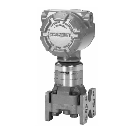
Summarization of Contents
SECTION 1: INTRODUCTION
USING THIS MANUAL
Explains how to use the manual for installing, operating, and maintaining transmitters.
SECTION 2: INSTALLATION
OVERVIEW
Provides general, mechanical, and electrical installation considerations.
SAFETY MESSAGES
Highlights critical safety precautions for personnel performing installation.
Warnings
Lists specific warnings, such as explosion hazards during operation.
GENERAL CONSIDERATIONS
Discusses factors for accurate measurement and safe operation.
MECHANICAL CONSIDERATIONS
Covers mechanical aspects of transmitter mounting and installation.
Process Connections and Interfaces
Details how to connect the transmitter to process piping.
Impulse Piping
Provides guidelines for installing impulse piping for accurate measurements.
Mounting Configurations
Explains different mounting options and their configurations.
Conduit
Describes conduit connection options and installation requirements.
Electrical Housing
Covers electrical housing details and orientation.
ELECTRICAL CONSIDERATIONS
Provides information for making electrical connections to the transmitter.
SECTION 3: CALIBRATION
OVERVIEW
Introduces the calibration process and key concepts for transmitters.
SAFETY MESSAGES
Highlights critical safety precautions for personnel performing calibration.
CALIBRATION OVERVIEW
Familiarizes users with the fundamentals of Rosemount 3150 Series transmitter calibration.
Calibration Considerations
Details factors affecting calibration, including range and zero adjustments.
Definitions
Defines key terms used in transmitter calibration procedures.
Span Adjustment Range
Explains the adjustable range for span calibration.
Zero Adjustment Range
Details the range and methods for zero adjustment.
CALIBRATION PROCEDURES
Outlines the recommended steps for calibrating pressure transmitters.
Span and Zero Adjustment
Describes the process of adjusting zero and span.
Zero Based Calibration Procedure (LRV is zero DP)
Provides steps for calibrating with a zero based span.
Elevated or Suppressed Zero Calibration Procedure
Explains how to perform calibration with elevated or suppressed zeros.
Coarse Zero Select Jumper Position Selection Procedure
Details how to select the coarse zero jumper for calibration.
Damping Adjustment
Covers adjustment of the damping potentiometer for output stability.
Correction for High Static Line Pressure
Explains how to correct for static line pressure effects on calibration.
High Static Line Pressure Span Effect on Range Codes 1, 2 and 3 DP Transmitters
Discusses span effect on specific DP transmitter ranges due to static pressure.
High Static Line Pressure Span Correction for Range Code 4 and 5 DP Transmitters
Details span correction for specific DP transmitter ranges under static pressure.
High Static Line Pressure Zero Correction for Differential Pressure Transmitters (All Ranges)
Describes how to correct zero shift from high static line pressure.
Linearity
Notes that linearity is factory optimized and requires no field adjustment.
SECTION 4: OPERATION
OVERVIEW
Provides a brief description of basic 3150 series pressure transmitter operations.
TRANSMITTER THEORY OF OPERATION
Illustrates the operation of the 3150 series pressure transmitter.
THE SENSOR CELL
Explains the function and components of the transmitter's sensor cell.
DEMODULATOR
Describes the demodulator's role in converting AC signal to DC signal.
OSCILLATOR
Details the oscillator's function in determining frequency based on capacitance.
VOLTAGE REGULATOR
Explains the voltage regulator's function in providing constant reference voltage.
CURRENT CONTROL
Describes the current control amplifier's role in the 4-20mA loop.
CURRENT LIMIT
Explains the function of the current limiter to prevent output exceeding limits.
REVERSE POLARITY PROTECTION
Notes that a diode provides reverse polarity protection.
SECTION 5: MAINTENANCE & TROUBLESHOOTING
OVERVIEW
Outlines techniques for checking components, disassembly, and troubleshooting.
SAFETY MESSAGES
Highlights critical safety precautions for personnel performing maintenance.
GENERAL CONSIDERATIONS
Discusses minimal scheduled maintenance and calibration checks.
TEST TERMINAL
Explains the use of test terminals for in-process checks.
ELECTRONICS ASSEMBLY CHECKOUT
Describes how to check the electronics assembly for malfunctions.
SENSOR MODULE CHECKOUT
Details how to check the sensor module for defects.
DISSASSEMBLY PROCEDURE
Outlines the steps for disassembling the transmitter.
Process Flange Removal
Describes the procedure for removing the process flange.
Electrical Housing Disassembly
Details the steps for disassembling the electrical housing.
Electronics Assembly Removal
Explains how to remove the electronics assembly.
Terminal Block Removal
Describes how to remove the terminal block assembly.
REASSEMBLY PROCEDURE
Provides instructions for reassembling the transmitter components.
Electrical Housing Reassembly
Details the steps for reassembling the electrical housing.
Preliminary
Covers preliminary steps for reassembly, including o-rings and filters.
Electronics Assembly Installation
Explains how to install the electronics assembly.
Terminal Block Assembly
Describes how to install the terminal block assembly.
Electronics Housing Cover Installation
Details how to install the electronics housing cover.
Process Flange Reassembly
Explains the procedure for reassembling the process flange.
POST-ASSEMBLY TESTS
Outlines the tests to be performed after reassembly.
SECTION 6: TRANSMITTER SPARE PARTS
OVERVIEW
Provides information on spare part kits for Rosemount transmitters.
SAFETY MESSAGES
Highlights critical safety precautions for handling spare parts.
GENERAL CONSIDERATIONS
Discusses factors for maintaining product qualification and traceability.
SPARE PARTS SHELF LIFE
Provides information on storage and shelf life of spare parts.
IMPACT ON TRANSMITTER QUALIFIED LIFE
Explains the effect of spare parts on the transmitter's qualified life.
TRANSMITTER SPARE PARTS LIST
Lists available spare parts for the transmitters.
Miscellaneous Items
Lists miscellaneous spare parts such as cover wrenches.


Need help?
Do you have a question about the 3154 and is the answer not in the manual?
Questions and answers