Table of Contents
Advertisement
Available languages
Available languages
Quick Links
Harbor Breeze® is a registered trademark
of LF, LLC. All Rights Reserved.
Federal regulations require ceiling fans with light kits manufactured or imported after
January 1, 2009, to limit total wattage consumed by the light kit to 190W. Therefore,
this fan is equipped with a wattage limiting device.
ATTACH YOUR RECEIPT HERE
Serial Number
Questions, problems, missing parts? Before returning to your retailer, call our customer
service department at
5 p.m., EST, Friday.
EB14741
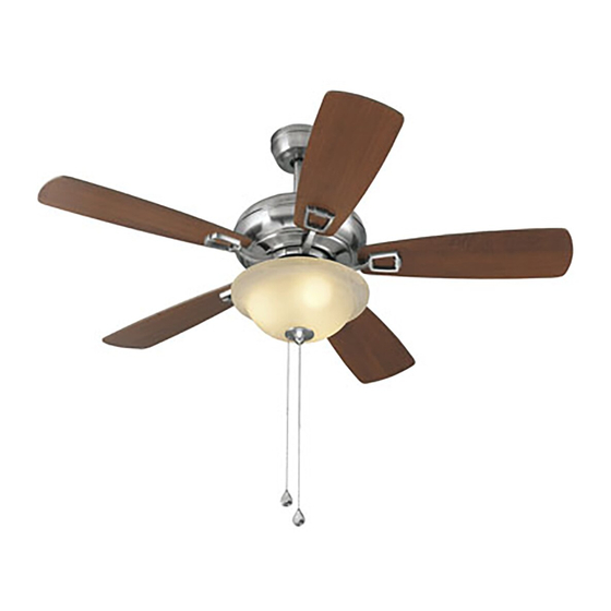
WINDRISE CEILING FAN
Purchase Date
1-800-643-0067, 8 a.m. - 6 p.m., EST, Monday - Thursday, 8 a.m. -
1
ITEM #0593745
MODEL #E-TLEII44BNK5C1
Español p. 19
Lowes.com/harborbreeze
Advertisement
Chapters
Table of Contents

Subscribe to Our Youtube Channel
Related Manuals for Harbor Breeze WINDRISE E-TLEII44BNK5C1


Summary of Contents for Harbor Breeze WINDRISE E-TLEII44BNK5C1
- Page 1 ITEM #0593745 WINDRISE CEILING FAN MODEL #E-TLEII44BNK5C1 Harbor Breeze® is a registered trademark of LF, LLC. All Rights Reserved. Español p. 19 Federal regulations require ceiling fans with light kits manufactured or imported after January 1, 2009, to limit total wattage consumed by the light kit to 190W. Therefore, this fan is equipped with a wattage limiting device.
-
Page 2: Table Of Contents
TABLE OF CONTENTS Safety Information ........................2 Package Contents ........................4 Hardware Contents ...........................5 Preparation ...........................5 Initial Installation ........................6 Wiring ...........................8 Final Installation ........................9 Installing Fan Without Light Kit ...................12 Operating Instructions ......................14 Care and Maintenance .......................15 Troubleshooting........................16 Warranty ..........................17 Replacement Parts List ......................18 SAFETY INFORMATION READ AND SAVE THESE INSTRUCTIONS •... - Page 3 SAFETY INFORMATION WARNING To reduce the risk of fire, electrical shock or personal injury, mount fan to outlet box marked "ACCEPTABLE FOR FAN SUPPORT OF 35 LBS. OR LESS" and use mounting screws provided with the outlet box. Most outlet boxes commonly used for the support of lighting fixtures are not acceptable for fan support and may need to be replaced.
-
Page 4: Package Contents
PACKAGE CONTENTS PART DESCRIPTION QUANTITY PART DESCRIPTION QUANTITY Downrod (preassembled) Switch Housing Cap (preassembled) Canopy (preassembled) Switch Housing Cap Screw Mounting Bracket (preassembled) Motor Housing Finial (preassembled) Yoke Cover (preassembled) Glass Shade Light Kit Fitter Rubber Washer (preassembled) (preassembled) Blade Balancing Kit Bulb Blade Arm... -
Page 5: Hardware Contents
HARDWARE CONTENTS (shown actual size) Three-C Clip* Qty. 1 Qty. 15 + 1 extra Pull Chain *US Patent Pending Extension Qty. 2 Clip (preassembled) Qty. 3 PREPARATION Before beginning assembly of product, make sure all parts are present. Place motor on carpet or on foam to avoid damage to finish. -
Page 6: Initial Installation
INITIAL INSTALLATION Turn off circuit breakers or fuse and wall switch to the fan supply line leads. DANGER: Failure to disconnect power supply prior to installation may result in serious injury or death. 2. Determine mounting method to use. A. Standard mount B. - Page 7 INITIAL INSTALLATION Secure mounting bracket (C) to outlet box (not STANDARD MOUNT ANGLE MOUNT included) using screws, spring washers and flat washers provided with the outlet box. *NOTE: It is very important you use the proper hardware when installing the mounting bracket (C) as this will support the fan.
-
Page 8: Wiring
INITIAL INSTALLATION Install hanging ball of downrod (A) into opening of mounting bracket (C). Align one of the slots in hanging ball with the tab in mounting bracket (C). DANGER: Failure to align one of the slots in hanging ball with the tab in mounting bracket (C) may result in serious injury or death. -
Page 9: Final Installation
WIRING Wrap electrical tape (not included) around each individual clip (DD) down to the wire. WARNING: Make sure no bare wire or wire strands are visible after making connections. Place green and white connections on opposite side of box from the black and blue connections. Gently push wires and clips (DD) into outlet box. - Page 10 FINAL INSTALLATION Should it become necessary to remove blade arm (S) from motor housing (D), follow these steps: Remove blade arm screws (T) and washers (U) from underside of motor housing (D) and remove blade arm assembly. Remove safety screw (V) and metal tab (W) from blade arm wall.
- Page 11 FINAL INSTALLATION If you wish to use the fan WITH the light kit, remove finial (O), finial plate (I), rubber washer (Q) and hex nut (K) from the threaded rod at the bottom of the light kit fitter (F). Save hardware for later use. Threaded Install bulbs (H).
-
Page 12: Installing Fan Without Light Kit
FINAL INSTALLATION Attach pull chain extensions (CC) or custom pull chain extensions (not included) to fan and light pull chains. Assembly is now complete. Hardware Used Pull Chain Extension INSTALLING FAN WITHOUT LIGHT KIT If you do NOT wish to use the light kit, remove 3 switch housing cap screws (N) from switch housing cap (M) located on switch housing preassembled to motor housing (D). - Page 13 INSTALLING FAN WITHOUT LIGHT KIT Remove the hex nut (K) and lock washer (L) from the threaded rod at the top of the light kit WHITE BLACK fitter (F). Unscrew the switch housing cap (M) to remove it from the light kit fitter (F), and then gently feed the BLACK and WHITE wires from the light kit fitter (F) through the hole in the middle of the switch housing cap (M).
-
Page 14: Operating Instructions
OPERATING INSTRUCTIONS The fan pull chain, located on the switch housing of motor housing (D) has four positions to control fan speed. One pull is HIGH, two is MEDIUM, three is LOW and four turns the fan OFF. Switch Housing If applicable, the light pull chain in the middle is used to turn the light ON or OFF. -
Page 15: Care And Maintenance
OPERATING INSTRUCTIONS 3a. In warmer weather, setting the reverse switch in the DOWN position will result in downward airflow creating a wind chill effect. 3b. In cooler weather, setting the reverse switch in the UP position will result in upward airflow that can help move stagnant, hot air off the ceiling area. -
Page 16: Troubleshooting
TROUBLESHOOTING WARNING: Before beginning work, shut off the power supply to avoid electrical shock. PROBLEM POSSIBLE CAUSE CORRECTIVE ACTION Fan does not move. 1. Reverse switch not engaged. 1. Push switch firmly either up or down. 2. Power is off or fuse is blown. 2. -
Page 17: Warranty
WARRANTY LIMITED LIFETIME WARRANTY: The distributor warrants this fan to be free from defects in workmanship and materials present at time of shipment from the factory for Lifetime limited from the date of purchase. This warranty applies only to the original purchaser. The distributor agrees to correct any defect at no charge or, at our option, replace the ceiling fan with a comparable or superior model. -
Page 18: Replacement Parts List
1-800-643-0067, 8 a.m. - 6 p.m., EST, Monday - Thursday, 8 a.m. - 5 p.m., EST, Friday. PART DESCRIPTION PART# Glass Shade 593745-P Printed in China Harbor Breeze® is a registered trademark of LF, LLC. All Rights Reserved. Lowes.com/harborbreeze NOLI1412... - Page 19 EXPLODED VIEW/ VISTA DETALLADA...
- Page 20 Quick Reference Guide Guía de referencia rápida BEFORE BEGINNING INSTALLATION/ ANTES DE COMENZAR LA INSTALACIÓN This is a general overview of assembly process. Read the complete installation manual for detailed instructions and safety information./Este es un resumen general del proceso de ensamblaje. Lea el manual de instalación completo para obtener instrucciones detalladas e información de seguridad.
- Page 21 INSTALLATION OVERVIEW/ DESCRIPCIÓN GENERAL DE LA INSTALACIÓN Turn Off Power Source Turn Off Power Source Turn Off Power Source Turn Off Power Source Install Mounting Bracket Apague la fuente de alimentación Turn off power source Turn off power source Turn off power source Turn off power source Instale el soporte de montaje STANDARD...
- Page 22 INSTALLATION OVERVIEW/ DESCRIPCIÓN GENERAL DE LA INSTALACIÓN Hang Fan on Bracket Connect Wiring Cuelgue el ventilador del soporte Conecte el cableado Green/Verde White/Blanco Ground Tierra Black/Negro Green/Verde Green/Verde Green/Verde Green/Verde Black/Negro Black/Negro Black/Negro Black/Negro White/Blanco White/Blanco White/Blanco White/Blanco Lengüeta Blue/Azul See Page See Page See Page...
- Page 23 ARTÍCULO # 0593745 VENTILADOR DE TECHO WINDRISE ® Harbor Breeze es una marca registrada de LF, LLC. Todos los derechos reservados. MODELO # E-TLEII44BNK5C1 Los reglamentos federales requieren que los ventiladores de techo con kit de iluminación fabricados o importados después del 1 de enero de 2009, tengan un límite de vataje total consumido por el kit de iluminación de 190 vatios.
-
Page 24: Información De Seguridad
ÍNDICE Información de seguridad ....................20 Contenido del paquete .......................22 Aditamentos ........................23 Preparación ........................23 Instalación inicial ........................24 Cableado ..........................26 Instalación final ....….…………….……………………….…………….……..…..27 Instalación del ventilador sin el kit de iluminación ..............30 Instrucciones de funcionamiento ..................32 Cuidado y mantenimiento ....................33 Solución de problemas .......................34 Garantía ..........................35 Lista de piezas de repuesto ....................36 INFORMACIÓN DE SEGURIDAD... - Page 25 INFORMACIÓN DE SEGURIDAD ADVERTENCIA Para reducir el riesgo de incendio, descargas eléctricas o lesiones personales, monte el ventilador en una caja de salida marcada como "ACCEPTABLE FOR FAN SUPPORT OF 35 LBS. OR LESS" (APTA PARA SOSTENER VENTILADORES DE 15,87 KG O MENOS) y utilice los tornillos de montaje que se proporcionan con la caja de salida.
-
Page 26: Contenido Del Paquete
CONTENIDO DEL PAQUETE PIEZA DESCRIPCIÓN CANTIDAD Tapa de la carcasa del PIEZA DESCRIPCIÓN CANTIDAD interruptor (preensamblada) Varilla (preensamblada) Tornillo de la tapa de la Base (preensamblada) carcasa del interruptor Abrazadera de montaje (preensamblado) Carcasa del motor Remate (preensamblado) Cubierta de la horquilla Pantalla de vidrio (preensamblada) Arandela de goma... -
Page 27: Aditamentos
ADITAMENTOS (se muestran en tamaño real) Tapa Sujetador triple C* Cant. 1 Cant. 15 + 1 adicional Extensión para *Patente estadounidense en trámite la cadena de tiro Cant. 2 Sujetador (preensamblado) Cant. 3 PREPARACIÓN Antes de comenzar a ensamblar el producto, asegúrese de tener todas las piezas. Ubique el motor sobre una alfombra o espuma para evitar dañar el acabado. -
Page 28: Instalación Inicial
INSTALACIÓN INICIAL Interrumpa el suministro de energía hacia el ventilador apagando los interruptores de circuito o el fusible y el interruptor de pared. PELIGRO: Si no interrumpe el suministro de electricidad antes de la instalación, pueden producirse lesiones graves o la muerte. 2. - Page 29 INSTALACIÓN INICIAL Asegure la abrazadera de montaje (C) a la caja MONTAJE MONTAJE de salida (no se incluye) con los tornillos, las ESTÁNDAR EN ÁNGULO arandelas de resorte y las arandelas planas que incluye la caja de salida. *NOTA: Es muy importante que use los aditamentos adecuados para instalar la abrazadera de montaje (C), ya que esta soportará...
-
Page 30: Cableado
INSTALACIÓN INICIAL Instale la bola para colgar en la varilla (A) en la abertura de la abrazadera de montaje (C). Alinee una de las ranuras en la bola para colgar con la lengüeta de la abrazadera de montaje (C). PELIGRO: Si no alinea una de las ranuras de la bola para colgar con la lengüeta en la abrazadera de montaje (C), pueden producirse lesiones graves o la Lengüeta... -
Page 31: Instalación Final
CABLEADO Cubra con cinta aislante (no se incluye) cada sujetador individual (DD) hacia abajo del cable. ADVERTENCIA: Asegúrese de que no haya conductores desnudos ni filamentos de cables visibles después de hacer las conexiones. Coloque las conexiones verdes y blancas en el lado opuesto de la caja donde se ubican las conexiones negras y azules. - Page 32 INSTALACIÓN FINAL Si fuera necesario retirar el brazo de las aspas (S) de la carcasa del motor (D), siga los siguientes pasos: Retire los tornillos del brazo del aspa (T) y las arandelas (U) de la parte inferior de la carcasa del motor (D) y retire el tornillo de seguridad (V) y la lengüeta de metal (W) de la pared del brazo del aspa.
- Page 33 INSTALACIÓN FINAL Si desea usar el ventilador CON el kit de iluminación, retire el remate (O), la placa del remate (I), la arandela de goma (Q) y la tuerca hexagonal (K) de la varilla roscada de la parte inferior del soporte del kit de iluminación (F). Aparte los aditamentos para su uso posterior.
-
Page 34: Instalación Del Ventilador Sin El Kit De Iluminación
INSTALACIÓN FINAL Conecte las extensiones para la cadena de tiro (CC) o las extensiones para la cadena de tiro personalizadas (no se incluyen) con las cadenas de tiro del ventilador y la luz. Ya ha terminado el ensamblado. Aditamentos utilizados Extensión para la cadena de tiro INSTALACIÓN DEL VENTILADOR SIN EL KIT DE ILUMINACIÓN... - Page 35 INSTALACIÓN DEL VENTILADOR SIN EL KIT DE ILUMINACIÓN Retire la tuerca hexagonal (K) y la arandela de seguridad (L) de la varilla roscada de la parte BLANCO NEGRO superior del soporte del kit de iluminación (F). Desenrosque la tapa de la carcasa del interruptor (M) para retirarla del soporte del kit de iluminación (F) y luego pase con cuidado los cables NEGRO y BLANCO del soporte del kit...
-
Page 36: Instrucciones De Funcionamiento
INSTRUCCIONES DE FUNCIONAMIENTO La cadena de tiro del ventilador, ubicada en la carcasa del interruptor de la carcasa del motor (D), tiene cuatro posiciones para controlar la velocidad del ventilador. Jale una vez para la velocidad ALTA; dos para la velocidad MEDIA; tres para la velocidad BAJA;... -
Page 37: Cuidado Y Mantenimiento
INSTRUCCIONES DE FUNCIONAMIENTO 3a. En climas más cálidos, la configuración del interruptor de reversa en la posición DOWN (HACIA ABAJO) creará un flujo de aire descendente que generará un efecto de viento refrescante. 3b. En climas más fríos, la configuración del interruptor de reversa en la posición UP (HACIA ARRIBA) creará... -
Page 38: Solución De Problemas
SOLUCIÓN DE PROBLEMAS ADVERTENCIA: Antes de comenzar cualquier trabajo, desconecte el suministro de electricidad para evitar descargas eléctricas. PROBLEMA CAUSA POSIBLE ACCIÓN CORRECTIVA El ventilador 1. El interruptor de reversa no 1. Mueva firmemente el interruptor hacia no se mueve. está... -
Page 39: Garantía
GARANTÍA GARANTÍA LIMITADA DE POR VIDA: El distribuidor garantiza que este ventilador no presenta defectos en la mano de obra ni en los materiales presentes al momento del transporte desde la fábrica durante un período limitado de por vida a partir de la fecha de compra. Esta garantía es válida solo para el comprador original. -
Page 40: Lista De Piezas De Repuesto
1-800-643-0067, de lunes a jueves de 8 a.m. a 6 p.m., y los viernes de 8 a.m. a 5 p.m., hora estándar del Este. PIEZA DESCRIPCIÓN PIEZA # Pantalla de vidrio 593745-P Impreso en China ® Harbor Breeze es una marca registrada de LF, LLC. Todos los derechos reservados. Lowes.com/harborbreeze NOLI1412...
Need help?
Do you have a question about the WINDRISE E-TLEII44BNK5C1 and is the answer not in the manual?
Questions and answers