Table of Contents
Advertisement
Available languages
Available languages
Harbor Breeze® is a registered trademark
of LF, LLC. All Rights Reserved.
ATTACH YOUR RECEIPT HERE
Serial Number
Questions, problems, missing parts? Before returning to your retailer, call our customer
service department at
5 p.m., EST, Friday.
EB14593
ECO BREEZE CEILING FAN
Purchase Date
1-800-643-0067, 8 a.m. - 6 p.m., EST, Monday - Thursday, 8 a.m. -
1
ITEM
MODEL
#E-TM52BNK5LED
Español p. 19
Lowes.com/harborbreeze
#0062325
LISTED
E192641
Advertisement
Chapters
Table of Contents

Subscribe to Our Youtube Channel
Related Manuals for Harbor Breeze E-TM52BNK5LED


Summary of Contents for Harbor Breeze E-TM52BNK5LED
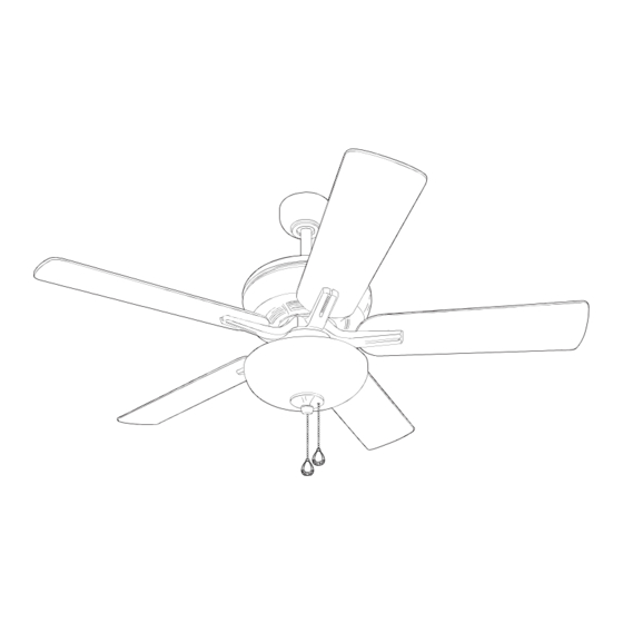
- Page 1 ITEM #0062325 ECO BREEZE CEILING FAN MODEL #E-TM52BNK5LED Harbor Breeze® is a registered trademark Español p. 19 of LF, LLC. All Rights Reserved. LISTED ATTACH YOUR RECEIPT HERE E192641 Serial Number Purchase Date Questions, problems, missing parts? Before returning to your retailer, call our customer service department at 1-800-643-0067, 8 a.m.
-
Page 2: Table Of Contents
TABLE OF CONTENTS Safety Information ......................2 Package Contents ......................4 Hardware Contents ......................5 Preparation ........................5 Initial Installation ........................ 6 Fan Mounting ........................7 Wiring ..........................9 Final Installation ........................ 11 Operating Instructions ...................... 14 Care and Maintenance ...................... 16 Troubleshooting ........................ - Page 3 SAFETY INFORMATION WARNING WARNING WARNING To reduce the risk of fire, electrical shock or personal injury, mount fan to outlet box marked "ACCEPTABLE FOR FAN SUPPORT OF 35 LBS. OR LESS" and use mounting screws provided with the outlet box. Most outlet boxes commonly used for the support of lighting fixtures are not acceptable for fan support and may need to be replaced.
-
Page 4: Package Contents
PACKAGE CONTENTS PART DESCRIPTION PART DESCRIPTION QUANTITY QUANTITY Downrod Finial Plate (preassembled) Canopy Finial (preassembled) Mounting Bracket Pin (preassembled) Yoke Cover Clip (preassembled) Motor Housing Motor Screw (preassembled) Switch Housing Plate Lock Washer Canopy Cover (preassembled) Glass Shade Canopy Mounting Screw Blade Arm (preassembled) Blade... -
Page 5: Hardware Contents
HARDWARE CONTENTS (shown actual size) Fiber Blade Blade Screw Wire Washer Connector Qty. 15 Qty. 15 + 1 extra Qty. 4 + 1 extra PREPARATION Before beginning assembly of product, make sure all parts are present. Compare parts with package contents list and hardware contents list. -
Page 6: Initial Installation
INITIAL INSTALLATION Turn off circuit breakers and wall switch to the fan supply line leads. DANGER: Failure to disconnect power supply prior to installation may result in serious injury or death. Determine mounting method to use. A. Standard mount B. Angle mount IMPORTANT: If using the angle mount, ensure the ceiling angle is not steeper than 19°. -
Page 7: Fan Mounting
INITIAL INSTALLATION Secure mounting bracket (C) to outlet box (not included) using screws, spring washers and flat washers provided with the outlet box. *NOTE: It is very important you use the proper hardware when installing the mounting bracket (C) as this will support the fan. IMPORTANT: If using the angle mount, make sure open end of mounting bracket (C) is installed facing the higher point of the ceiling. - Page 8 FAN MOUNTING 2. Insert downrod (A) through canopy (B), canopy cover (G) and yoke cover (D). [NOTE: Canopy cover (G) must be turned with the smooth side toward the motor housing (E).] Thread wires from motor housing (E) through downrod (A). 3.
-
Page 9: Wiring
FAN MOUNTING If you decided to cut back the lead wires in Step 4, strip a 1/2 in. of insulation from end of white wire. Twist stripped ends of each strand of wire within the insulation with pliers (not included). Repeat Step 5 for black, blue (if applicable) and green wires. - Page 10 WIRING Choose wiring diagram (Fig. 1A, Fig. 1B or Fig. 1C) FAN AND LIGHT CONTROLLED BY PULL CHAINS FAN AND LIGHT CONTROLLED BY TWO WALL SWITCHES that fits your situation and make appropriate wiring connections as follows: [IMPORTANT: For each wire 120V POWER connection below, use one of the wire connectors FROM CEILING...
-
Page 11: Final Installation
WIRING Wrap electrical tape (not included) around each individual wire connector (CC) down to the wire. WARNING: Make sure no bare wire or wire strands are visible after making connections. Place GREEN and WHITE connections on opposite side of box from the BLACK and BLUE (if applicable) connections. - Page 12 FINAL INSTALLATION Partially insert three blade screws (AA) along with three fiber blade washers (BB) to attach one blade arm (I) to a blade (J). Then, tighten each blade screw (AA) starting with the one in the middle. Repeat with remaining blades (J). Hardware Used Blade Screw x 15...
- Page 13 FINAL INSTALLATION Connect male plug from motor housing (E) to female plug from light kit fitter (L), matching up the colors on the male plug with the colors on the female plug for correct fit. Make sure plugs are connected completely.
-
Page 14: Operating Instructions
FINAL INSTALLATION 8. Attach pull chain extensions (K) or custom pull chain extensions (not included) to the fan and light pull chains. OPERATING INSTRUCTIONS The pull chain located on the switch housing has four positions to control fan speed. One pull is HIGH, two is MEDIUM, three is LOW and four turns the fan OFF. - Page 15 OPERATING INSTRUCTIONS 3. Use the fan reverse switch, located on the switch housing, to optimize your fan for seasonal performance. A ceiling fan will allow you to raise your thermostat setting in summer and lower your Switch thermostat setting in winter without feeling a Housing difference in your comfort.
-
Page 16: Care And Maintenance
CARE AND MAINTENANCE At least twice each year, lower canopy (B) to check downrod (A) assembly, and then tighten all screws on fan. Clean fan with only a soft brush or lint-free cloth to avoid scratching the finish. Clean blades (J) with a lint-free cloth. You may occasionally apply a light coat of furniture polish to wood blades for added protection. -
Page 17: Limited Lifetime Warranty
TROUBLESHOOTING PROBLEM POSSIBLE CAUSE CORRECTIVE ACTION Fan operates but 1. Wires in canopy not wired properly. 1. Check wires in canopy and, if necessary, re-wire according to light fails. instructions on pages 10 and 11. 2. Wall switch to fan is off. 2. -
Page 18: Replacement Parts List
Lock Washer 62325-S Canopy Mounting Screw 62325-T Threaded Washer 62325-U Switch Housing Screw 62325-V Fitter Plate Screw Blade Screw 62325-AA Fiber Blade Washer 62325-BB Printed in China Harbor Breeze® is a registered trademark of LF, LLC. All Rights Reserved. Lowes.com/harborbreeze PWLI1410... - Page 19 ARTÍCULO # 0062325 VENTILADOR DE TECHO ECO BREEZE MODELO # E-TM52BNK5LED Harbor Breeze ® es una marca registrada de LF, LLC. Todos los derechos reservados. LISTED ADJUNTE SU RECIBO AQUÍ E192641 Número de serie Fecha de compra ¿Preguntas, problemas, piezas faltantes? Antes de volver a la tienda, llame a nuestro Departamento de Servicio al Cliente al 1-800-643-0067, de lunes a jueves de 8 a.m.
-
Page 20: Información De Seguridad
ÍNDICE Información de seguridad ....................20 Contenido del paquete .......................22 Aditamentos ........................23 Preparación ........................23 Instalación inicial ........................24 Montaje del ventilador......................25 Cableado ..........................27 Instalación final ........................29 Instrucciones de funcionamiento ..................32 Cuidado y mantenimiento ....................34 Solución de problemas ......................34 Garantía ..........................35 Lista de piezas de repuesto ....................36 INFORMACIÓN DE SEGURIDAD LEA Y GUARDE ESTAS INSTRUCCIONES Lea y comprenda completamente este manual antes de intentar ensamblar, instalar o usar el producto. - Page 21 INFORMACIÓN DE SEGURIDAD ADVERTENCIA ADVERTENCIA Para reducir el riesgo de incendio, descargas eléctricas o lesiones personales, monte el ventilador en una caja de salida marcada como "ACCEPTABLE FOR FAN SUPPORT OF 35 LBS. OR LESS" (APTA PARA SOSTENER VENTILADORES DE 15,87 KG O MENOS) y utilice los tornillos de montaje que se proporcionan con la caja de salida.
-
Page 22: Contenido Del Paquete
CONTENIDO DEL PAQUETE PIEZA DESCRIPCIÓN CANTIDAD PIEZA DESCRIPCIÓN CANTIDAD Varilla Placa del remate (preensamblada) Base Remate (preensamblado) Soporte de montaje Pasador (preensamblado) Cubierta de la horquilla Sujetador (preensamblado) Carcasa del motor Tornillo del motor Placa de la carcasa (preensamblado) del interruptor Arandela de seguridad Cubierta de la base (preensamblada) -
Page 23: Aditamentos
ADITAMENTOS (se muestran en tamaño real) Arandela del Tornillo aspa de fibra para aspa Conector de cables Cant. 15 Cant. 15 + 1 adicional + 1 adicional Cant. 4 PREPARACIÓN Antes de comenzar a ensamblar el producto, asegúrese de tener todas las piezas. Compare las piezas con la lista del contenido del paquete y la lista de aditamentos. -
Page 24: Instalación Inicial
INSTALACIÓN INICIAL Interrumpa el suministro de energía del ventilador apagando los interruptores de circuito y el interruptor de pared. PELIGRO: Si no interrumpe el suministro de electricidad antes de la instalación, pueden producirse lesiones graves o la muerte. Determine el método de instalación que utilizará. A. -
Page 25: Montaje Del Ventilador
INSTALACIÓN INICIAL Asegure el soporte de montaje (C) a la caja de salida (no se incluye) con los tornillos, las arandelas de resorte y las arandelas planas provistas con la caja de salida. *NOTA: Es muy importante que use los aditamentos adecuados para instalar el soporte de montaje (C), ya que este soportará... - Page 26 MONTAJE DEL VENTILADOR 2. Introduzca la varilla (A) a través de la base (B), de la cubierta de la base (G) y de la cubierta de la horquilla (D). (NOTA: La cubierta de la base (G) debe girarse con el lado liso apuntando hacia la carcasa del motor (E)].
-
Page 27: Cableado
MONTAJE DEL VENTILADOR Si decidió cortar los cables conductores en el paso 4, pele 1,27 cm del aislamiento del extremo del conductor blanco. Tuerza los extremos pelados de cada filamento de conductor dentro del aislamiento con pinzas (no se incluyen). Repita el paso 5 para los conductores negro, azul (si corresponde) y verde. - Page 28 CABLEADO VENTILADOR Y LUZ CONTROLADOS POR CADENAS DE TIRO Escoja el diagrama de cableado (Fig. 1A, Fig. 1B o Fig. 1C) que se ajuste a su situación y realice las conexiones del cableado adecuadas como se indica ALIMENTACIÓN DE 120 V a continuación: [IMPORTANTE: Utilice uno de los DESDE EL TECHO NEGRO (ALIMENTACIÓN)
-
Page 29: Instalación Final
CABLEADO Cubra con cinta aislante (no se incluye) cada conector de cables (CC) individual hacia abajo del cable. ADVERTENCIA: Asegúrese de que no haya conductores desnudos ni filamentos de conductores visibles después de hacer la conexión. Coloque las conexiones VERDES y BLANCAS en el lado opuesto de las conexiones NEGRAS y AZULES de la caja (si corresponde). - Page 30 INSTALACIÓN FINAL Inserte parcialmente tres tornillos para las aspas (AA), junto con tres arandelas para las aspas de fibra (BB) para fijar un brazo del aspa (I) a un aspa (J). Luego, apriete cada uno de los tornillos para las aspas (AA), comenzando por el que está...
- Page 31 INSTALACIÓN FINAL Conecte el enchufe macho de la carcasa del motor (E) al enchufe hembra del soporte del kit de iluminación (L) y haga coincidir los colores del enchufe macho con los del enchufe hembra para un ajuste correcto. Asegúrese de que los enchufes Enchufe estén conectados completamente.
-
Page 32: Instrucciones De Funcionamiento
INSTALACIÓN FINAL 8. Fije las extensiones de las cadenas de tiro (K) o las extensiones de cadenas de tiro a medida (no incluidas) al ventilador y la luz. INSTRUCCIONES DE FUNCIONAMIENTO La cadena de tiro ubicada en la carcasa del interruptor tiene cuatro posiciones para controlar la velocidad del ventilador. - Page 33 INSTRUCCIONES DE FUNCIONAMIENTO 3. Utilice el interruptor de reversa del ventilador, ubicado en la carcasa del interruptor, para optimizar el rendimiento de su ventilador según la estación del año. Un ventilador de techo le Carcasa del permitirá elevar la configuración de su termostato interruptor en verano y disminuirla en invierno, sin sentir una diferencia en su comodidad.
-
Page 34: Cuidado Y Mantenimiento
CUIDADO Y MANTENIMIENTO Al menos dos veces al año, baje la base (B) para revisar en ensamble de la varilla (A) y luego apriete todos los tornillos en el ventilador. Limpie el ventilador solo con un cepillo suave o un paño que no produzca pelusas para evitar rayar el acabado. -
Page 35: Garantía
SOLUCIÓN DE PROBLEMAS PROBLEMA CAUSA POSIBLE ACCIÓN CORRECTIVA El ventilador 1. Los conductores de la base 1. Revise los conductores de la base y funciona pero no están bien conectados. si es necesario vuelva a conectarlos la luz no. de acuerdo con las instrucciones de las páginas 28 y 29. -
Page 36: Lista De Piezas De Repuesto
Tornillo de la carcasa 62325-U del interruptor Tornillo de la placa de soporte 62325-V Tornillo para aspa 62325-AA Arandela del aspa de fibra 62325-BB Impreso en China Harbor Breeze ® es una marca registrada de LF, LLC. Todos los derechos reservados. Lowes.com/harborbreeze...
Need help?
Do you have a question about the E-TM52BNK5LED and is the answer not in the manual?
Questions and answers