Table of Contents
Advertisement
Document Type: Service Manual
Version: V1.0 04102018
SERVICE MANUAL
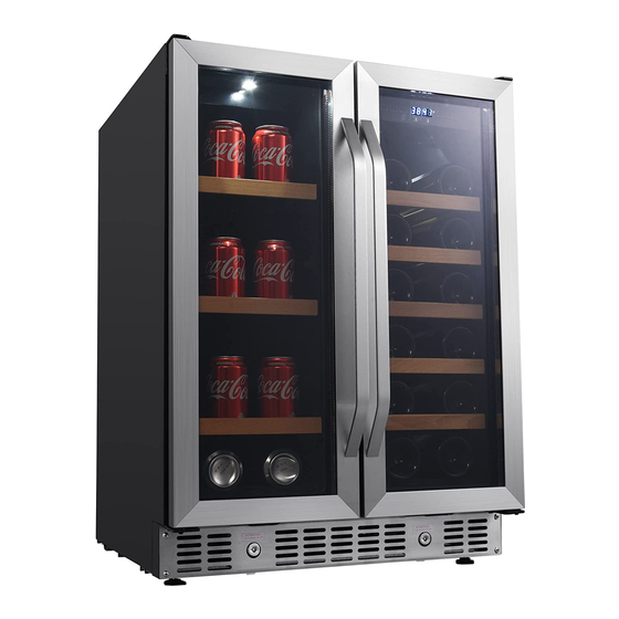
CWB1760FD
EdgeStar 24 Inch Built-In
Wine and Beverage Cooler
with French Doors
CAUTION: READ ALL SAFETY PRECAUTIONS IN THIS
MANUAL BEFORE SERVICING THE UNIT
CWB8420DZ
EdgeStar 24 Inch Built-In Wine
and Beverage Cooler
EdgeStar, 8606 Wall St, Suite 1800, Austin, TX 78754
support.edgestar.com • service@edgestar.com • edgestar.com
*Warranty service should be performed by an authorized service representative only.
Advertisement
Table of Contents
Troubleshooting

Related Manuals for EdgeStar CWB8420DZ


Summary of Contents for EdgeStar CWB8420DZ
- Page 1 French Doors CAUTION: READ ALL SAFETY PRECAUTIONS IN THIS MANUAL BEFORE SERVICING THE UNIT EdgeStar, 8606 Wall St, Suite 1800, Austin, TX 78754 support.edgestar.com • service@edgestar.com • edgestar.com *Warranty service should be performed by an authorized service representative only.
-
Page 2: Table Of Contents
5.2 CWB8420DZ Wiring Diagram ......................24 5.3 Power PCB ............................24 5.4 Control PCB ............................25 6. Compressor Compartment Components ....................26 7. Reversing the Door Swing (CWB8420DZ) ....................27 8. Replacing Main Components ........................28 8.1 Replacing the Control PCB (CWB1760FD) ................... 28... - Page 3 8.3.2 Replacing the Evaporator Fan and Temperature Sensor in the Upper Zone (CWB8420DZ) ..34 8.3.3 Replacing the PTC Heater, Fan and Temperature Sensor in the Lower Zone (CWB8420DZ) ..34 8.4 Replacing the Power PCB (CWB1760FD and CWB8420DZ) ..............35 8.5 Replacing the Condenser Fan (CWB1760FD and CWB8420DZ) ............
- Page 4 9.5.1 “E1” .............................. 53 9.5.2 “E2” .............................. 53 9.5.3 “E3” .............................. 53 9.5.4 “E4” .............................. 54 9.5.5 “E5” .............................. 54 9.5.6 “E6” .............................. 54 9.5.7 “E7” .............................. 54 10. FAQs ................................ 55...
-
Page 5: Safety Warnings
WARNING Before servicing, make sure to unplug the appliance. After servicing replace all parts before operating the appliance. Failure to do so could result in death, electrical shock or personal injury. All servicing must be carried out by qualified technicians. Repairs done incorrectly may cause considerable risk to the user. -
Page 8: Safety Instructions For R600A Refrigerant
1.2 Safety Instructions for R600a Refrigerant... -
Page 9: Refrigeration System
2. Refrigeration System 2.1 Refrigerant Cycle Diagrams CWB1760FD 1. Compressor 8. Solenoid Valve 2. Spiral Tube 9. Capillary 3. Condenser Fan 10. Evaporator Fan 4. Condenser 11. Accumulator 5. Hot Pipe 12. Evaporator 6. Process Tube 13. Suction Tube 7. Filter Dryer 14. - Page 10 CWB8420DZ 1. Compressor 7. Filter Dryer 2. Spiral Tube 8. Capillary Tube 9. Evaporator Fan 3. Condenser Fan 4. Condenser 10. Accumulator 5. Hot Pipe 11. Evaporator 6. Process Tube 12. Suction Tube 13. Process Tube...
-
Page 11: Refrigeration Process
2.2 Refrigeration Process All refrigeration units cool by removing heat from the cabinet rather than pumping in cool air. In a conventional refrigeration unit, liquid refrigerant enters the evaporator and vaporizes due to the low pressure, creating a very cold surface which removes heat from inside the cabinet. This causes the refrigerant to boil into a vapor state and be drawn into the compressor. -
Page 12: Refrigeration System Components
2.3 Refrigeration System Components Compressor The compressor is the "heart" of the refrigeration unit, consisting of an electrical motor and a "pump" sealed inside a steel case. The compressor used on R134A refrigerant systems is virtually the same in external appearance as the compressor used with R600a refrigerants. However, due to changes in lubricants and other internal differences, the compressors are not to be interchanged, otherwise system failure will result. -
Page 13: Service Precautions For R600A Refrigerant
2.4 Service Precautions for R600A Refrigerant Features of R600a refrigerant Achromatic and odorless gas. Flammable gas with ignition (explosion) at 494°C. Upper/lower explosion limit: 1.8%~8.4%/Vol. Features of the R600a refrigeration unit Charging of around 60% refrigerant compared with a R134a model The suction pressure is below 1bar (abs) during the operation. - Page 14 Recharging the Compressor Before refilling the refrigerant, you must perform the test according to “TROUBLESHOOTING GUIDE”. When the defects are found, you must discharge the residual refrigerant (R600a) in the outdoors. For discharging the refrigerant R600a, break the narrow portion of tube extension by hand or with a pipe cutter.
-
Page 15: Performance Checks
After the leak test, check the temperature of each part. Check (by touch) if the CONDENSER and Hot Pipe are warm. Confirm that frost is uniformly distributed on the surface of the EVAPORATOR. 2.5 Performance Checks The following general information explains several methods for checking the performance of the refrigeration system. -
Page 16: Leak Testing
accumulation of frost. Where possible, check the capillary tube and straighten any kinks to relieve the restrictions. Check the unit’s performance. If the condition persists, replace the defective part. If the freeze-up condition does not exist and there is not a kink, you can assume that a foreign particle is causing the restriction. -
Page 17: Exploded Diagrams And Part Lists
3. Exploded Diagrams and Part Lists 3.1 CWB1760FD Exploded Diagram... -
Page 18: Cwb1760Fd Parts List
3.2 CWB1760FD Parts List Description Qty. Description Qty. Cabinet Metal Rack Left Top Hinge Door Switch Plastic Post Extended Ventilation Grill Evaporator Assembly Ventilation Grill Right Top Hinge Right Bracket Light Cover Lock Assembly LED Light Door Axle Fan Motor Bottom Hinge Plate Air Channel Cover Left Bracket... -
Page 19: Cwb8420Dz Exploded Diagram
3.3 CWB8420DZ Exploded Diagram... -
Page 20: Cwb8420Dz Parts List
3.4 CWB8420DZ Parts List Description Qty. Description Cabinet 33. Wooden Front Left Top Hinge 34. Full Shelf Decoration Plug 35. Metal Rack 2 Plastic Post 36. Metal Rack 1 Evaporator Assembly 37. Active Charcoal Filter Right Top Hinge 38. Fan Guard LED Light 39. -
Page 21: Electronic Controls
4. Electronic Controls 4.1. Modes Cooling mode: When the set temperature is lower than the cabinet temperature, the unit operates in cooling mode. Heating mode: When the set temperature is higher than the cabinet temperature, the unit operates in heating mode. -
Page 22: Other Functions
The rest of the time the fans will be off unless the unit is in dynamic climate mode in which case the fan will cycle on 20 seconds and off 30 seconds to circulate air inside the cabinet. Divider Fan (CWB8420DZ) The fan motor positioned in the middle divider. When the set temperature of the lower zone is lower than the cabinet temperature the fan will operate. -
Page 23: Control System Self-Check
4.5 Control System Self-Check The Display/Control PCB has a self-check function. Press and hold the “LIGHT” and “DOWN” keys at the same time for 5 seconds, the indicator light will flash once to confirm the input and the unit will activate the self-check program. The following tests will be seen, otherwise replace the PCBs: LED indicators will be ON one by one. -
Page 24: Cwb8420Dz Wiring Diagram
5.2 CWB8420DZ Wiring Diagram 5.3 Power PCB... -
Page 25: Control Pcb
5.4 Control PCB... -
Page 26: Compressor Compartment Components
6. Compressor Compartment Components 1. Joint of Condenser Outlet Tube and Hot Pipe Inlet Tube 2. Compressor Terminal Cover (Relay and OLP inside) 3. Process Pipe 4. Electrical Box (Power PCB inside) 5. Compressor 6. Suction Pipe 7. Discharge Pipe 8. -
Page 27: Reversing The Door Swing (Cwb8420Dz)
7. Reversing the Door Swing (CWB8420DZ) The door of this unit can be mounted so it swings open from either the left or right side. It is delivered with the door opening from the left side. Follow these instructions to reverse the door swing. -
Page 28: Replacing Main Components
8. Replacing Main Components 8.1 Replacing the Control PCB (CWB1760FD) 1. Remove all shelves and lay the unit on its back. 2. Remove the four screws that secure the PCB box to the top of cabinet. 3. Carefully pull down the PCB box and disconnect the wires from the control PCB. 4. -
Page 29: Replacing The Evaporator Fan And Temperature Sensor (Cwb1760Fd)
8.2 Replacing the Evaporator Fan and Temperature Sensor (CWB1760FD) 1. Remove the back panel from either side of the cabinet by removing the four screws (in red) holding it in place. 2. Move the panel to the side to access the wire connector for the fan and the wiring to the temperature sensor. -
Page 30: Sensor Test Resistance Table
8.2.1 Sensor Test Resistance Table MEASURED TEMPERATURE RESISTANCE OF SENSOR (°C) (kΩ) 116.55 104.97 94.67 85.49 77.30 69.99 63.44 57.58 53.32 47.60 43.35 39.53 36.08 32.97 30.16 27.62 25.32 23.24 21.35 19.63 18.07 16.65 15.35 14.17 13.10 12.11 11.21 10.39 10.00 9.63 8.94... -
Page 31: Replacing Components In And Around The Middle Divider (Cwb8420Dz)
8.3 Replacing Components In and Around the Middle Divider (CWB8420DZ) Exploded Diagram of Middle Divider 1. Screw 2. Flat head screw 3. Top plate of middle divider 4. Air duct assembly 5. Foam support of middle divider 6. Fan motor 8. -
Page 32: Replacing The Fan And Control Pcb In The Middle Divider (Cwb8420Dz)
8.3.1 Replacing the Fan and Control PCB in the Middle Divider (CWB8420DZ) 1. Remove all shelves. 2. Remove the five screws holding the bottom plate to the middle divider. 3. Remove the four screws holding the top plate to the middle divider. - Page 33 5. To replace the fan motor pull it free from the four rubber plugs holding it in place then disconnect its wiring connector (in red.) Install new fan in reverse order. 6. To replace the control PCB carefully remove any bonding glue (in yellow), disconnect the wire connectors (in red) and slide the PCB to the left or right to remove it from the display housing.
-
Page 34: Replacing The Evaporator Fan And Temperature Sensor In The Upper Zone (Cwb8420Dz)
8.3.2 Replacing the Evaporator Fan and Temperature Sensor in the Upper Zone (CWB8420DZ) 1. Remove all shelves. ○ ○ 2. Remove the screws 1 that secure the upper air channel cover to the cabinet. 3. Disconnect the fan motor wiring connector. Then pull out the upper air channel cover. -
Page 35: Replacing The Power Pcb (Cwb1760Fd And Cwb8420Dz)
8.4 Replacing the Power PCB (CWB1760FD and CWB8420DZ) ○ ○ 1. Remove the five screws 1 that fix the rear grill 2 to the cabinet. ○ ○ 2. Remove the screws 3 and 6 that hold the electrical box to the side of the cabinet. -
Page 36: Replacing Kick Plates
8.6 Replacing Kick Plates 8.6.1 Kick Plate on CWB1760FD 1. Lay the unit on its back and remove the four screws on the front of the kick plate and the two screws on the bottom. 2. Remove the four hidden screws holding the top of the kick plate to the bottom of the cabinet by inserting a Phillips screwdriver into the holes on the bottom of the kick plate. -
Page 37: Kick Plate On Cwb8420Dz
8.6.2 Kick Plate on CWB8420DZ 1. Lay the unit on its back and remove the four silver screws on the front of the kick plate and the two screws on the bottom. 2. Remove the four hidden screws holding the top of the kick plate to the bottom of the cabinet by inserting a Phillips screwdriver into the holes on the bottom of the kick plate. -
Page 38: Replacing Led Lights (Cwb1760Fd & Cwb8420Dz)
8.7 Replacing LED Lights (CWB1760FD & CWB8420DZ) 1. Remove all shelves. 2. Carefully remove the LED light cover with a small blade or your fingernail. 3. Carefully pull down to remove the LED light and replace it with a new one. -
Page 39: Replacing The Evaporator Assembly
8. After replacing the evaporator assembly, make sure to reinstall the four foam blocks ○ ○ 3 and 5 to their original positions for the CWB8420DZ. For the CWB1760FD make sure ○ that the foam blocks 2 are reinstalled. This is very important. -
Page 40: Replacing The Compressor, Compressor Ptc Starter And Overload Protector
8.9 Replacing the Compressor, Compressor PTC Starter and Overload Protector NOTE: Before replacing any component of the refrigeration system, make sure to read the instructions “Service Precautions for R600A System”. All replacement compressors are charged with the correct amount of oil and a holding charge of dry nitrogen. -
Page 41: Replacing The Condenser
8.11 Replacing the Condenser NOTE: Before replacing any component of the refrigeration system, make sure to read the instructions “Service Precautions for R600A System”. 1. Disconnect the unit from its power source. 2. Remove all R600a from the unit in a well ventilated area. ○... -
Page 42: Leveling The Door(S) And Hinge Adjustments
8.12 Leveling the Door(s) and Hinge Adjustments ○ Lay the unit on its back and loosen the screws ○ Adjust the glass door 3 to make sure the door top is parallel with the cabinet top then tighten the screws. Hinge adjustments are necessary when: ... -
Page 43: Troubleshooting
9. Troubleshooting 9.1 Troubleshooting Guide PROBLEM POSSIBLE CAUSE SOLUTION Appliance is not connected to a Connect the appliance to power. power supply. Appliance does not Switch on the appliance. The appliance is turned off. turn on. Circuit breaker tripped or blown fuse. Switch on circuit breaker or replace fuse. - Page 44 “E0” indicates the communication error for 3 zone models. “E1” indicates that the temperature sensor is open circuit. “E2” indicates that the temperature sensor is short circuit. “E3” indicates that the defrost sensor Display “E0”, “E1”, Call for service.
-
Page 45: Diagnostic Guide
Is the hot pipe hot? SYMPTOM DIAGNOSIS For models - Dual zone with single door (CWB8420DZ) The displayed temperature is 1. Is the ambient temperature too high (more than 35°C)? higher than the set temperature 2. Is the ventilation blocked? in the upper zone. - Page 46 The temperature in the upper 1. Is the fan motor in the lower zone is defective? zone is normal but the displayed 2. Is the PTC heater defective? 3. Is there leaking between the upper zone and lower zone? temperature in the lower zone is lower than the set temperature.
-
Page 47: Troubleshooting The Refrigerant System
9.3 Troubleshooting the Refrigerant System Once it has been determined that the other systems are working properly, a sealed system problem can be confirmed using the table when the unit is not cooling or not cooling enough. Symptom Cause Action The evaporator cools down and warms Moisture in the Replace the refrigerant. -
Page 48: Special Detailed Diagnosis
9.4 Special Detailed Diagnosis 9.4.1 Testing the Power PCB & Display/Control PCB 1. The control system including the POWER PCB and DISPLAY/CONTROL PCB operates when the unit is powered on. If the unit is receiving power and is switched ON but is not operating check the control system including the power PCB, display/control PCB and connecting wires. -
Page 49: Testing The Fan In The Middle Divider (Cwb8420Dz)
Connect the fan motor to a 12V DC power source. If the fan fails to operate, it is defective and must be replaced. 9.4.4 Testing the Fan in the Middle Divider (CWB8420DZ) 1. This fan motor operates independent from the compressor. When the set temperature of lower zone is not met and is lower than the actual storage temperature the fan runs. -
Page 50: Overload Protector
9.4.7 Overload Protector The overload protector prevents the compressor from burning out its electrical windings in the event the compressor becomes overheated or draws too much current. The overload trips, opening the circuit to the compressor. If it does this repeatedly, the compressor is said to be cycling on the overload. -
Page 51: Run Capacitor
Checking the PTC Device 1. Disconnect the unit from the power source. 2. Discharge the capacitor and remove the wires from the PTC device terminals. 3. Allow the PTC to cool to room temperature. 4. Remove the PTC device. 5. Using an ohmmeter, check the resistance between the PTC device terminals. The ohmmeter should register between 3 and 20 ohms. -
Page 52: Abnormal Vs. Normal Noise
9.4.10 Abnormal Vs. Normal Noise Compressor Noise The working of the electrical motor and the pump inside the compressor will cause noise during its run time. The noise should be stable and not exceed 42 dB(A). If the noise is excessive, the compressor is defective and should be replaced. Aging rubber legs or incorrect leg mounting (Too loose or too tight) also generates an abnormal noise. -
Page 53: Solenoid Valve (Cwb1760Fd)
The foam blocks at the two sides of evaporator are lost or damaged. Replace the foam. The temperature sensor has failed. The compressor operates continuously & independent from the set temperature. At the same time the condenser fan motor does not operate. The POWER PCB has failed and must be replaced. - Page 54 Reroute a new wire. 9.5.4 “E4” “E4” indicates the defrosting sensor in the evaporator is a short circuit. It may be caused by the following reasons: The temperature sensor is defective – Replace the thermistor. The Power PCB is defective – Replace the Power PCB. The Control PCB is defective –...
-
Page 55: Faqs
10. FAQs 10.1 What are the main concerns with storage conditions to collectors and consumers of fine wine? Light, humidity, temperature and vibration. 10.2 What is the ideal temperature for wine? The ideal temperature to store wines is between 52ºF and 57ºF (11ºC~14ºC). However, any temperature between 41º~72ºF (5º~22ºC) will suffice as long as it remains constant. - Page 56 10.9 Interior fan motors cycle on and off even when the set temperature has been reached In order to circulate the air and maintain the set temperature inside the cabinet the inside fans must cycle on and off when the compressor is off in Dynamic Cooling Mode. The fans will cycle ON and OFF approximately every 20 seconds.
- Page 57 DATE REVISION NOTES 4/10/2018 INITIAL DOCUMENT EdgeStar, 8606 Wall St, Suite 1800, Austin, TX 78754 support.edgestar.com • service@edgestar.com • edgestar.com *Warranty service should be performed by an authorized service representative only.
Need help?
Do you have a question about the CWB8420DZ and is the answer not in the manual?
Questions and answers