Sign In
Upload
Manuals
Brands
Beckhoff Manuals
Industrial PC
CX5140
User Manuals: Beckhoff CX5140 Intel Atom PC
Manuals and User Guides for Beckhoff CX5140 Intel Atom PC. We have
4
Beckhoff CX5140 Intel Atom PC manuals available for free PDF download: Manual
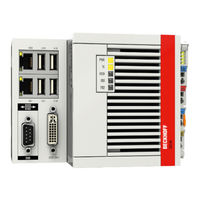
Beckhoff CX5140 Manual (93 pages)
Embedded-PC
Brand:
Beckhoff
| Category:
Industrial PC
| Size: 22 MB
Table of Contents
Table of Contents
3
1 Notes on the Documentation
5
Representation and Structure of Warnings
6
Documentation Issue Status
7
2 For Your Safety
8
Intended Use
8
Staff Qualification
9
Safety Instructions
9
3 Transport and Storage
11
Table 1 Dimensions and Weight of the Individual Modules
11
4 Product Overview
12
Table 2 Available Optional Interfaces for the Cx51X0
12
Configuration of the Cx51X0 Embedded PC
13
Fig. 1 Example: CX5140 Embedded PC
13
Table 3 Legend for the Configuration
13
Fig. 2 Name Plate Example
14
Name Plate
14
Table 4 Information on the Name Plate
14
Types
14
Fig. 3 Nomenclature for the Cx51X0 Embedded PC
15
Table 5: Order Details, Cx51X0 with Windows Embedded Compact 7
15
Table 6 Order Details, Cx51X0 with Windows Embedded Standard 7 P
15
Table 7 Order Details, Cx51X0 with Windows 10 Iot Enterprise
16
Architecture Overview
17
5 Interface Description
19
Usb (X100, X101, X102, X103)
19
Table 8 USB Interfaces (X100, X101, X102, X103), Pin Assignment
19
Fig. 4 USB Interfaces (X100, X101, X102, X103)
19
Ethernet RJ45 (X000, X001)
20
Table 9 Ethernet Interface X000 and X001, Pin Assignment
20
Fig. 5 Ethernet Interfaces X000, X001
20
DVI-I (X200)
21
Table 10 DVI-I Interface X200, Pin Assignment
21
Table 11 DVI-I Cross, Pin Assignment
21
Table 12 DVI-I Interface X200, Resolution at the Monitor
21
Fig. 6 DVI-I Interface X200
21
Optional Interfaces
22
DVI-D (N010)
22
Table 13 DVI-D Interface X300, Pin Assignment
22
Table 14 DVI-D Interface X300, Resolution at the Monitor
22
Fig. 7 DVI-D Interface X300
22
Displayport (N011)
23
Table 15 Displayport, Pin Assignment
23
Table 16 Displayport X300, Resolution at the Monitor
23
Fig. 8 Displayport X300
23
Audio Interface (N020)
24
Table 17 Line in /Line out Jack Plugs, Pin Assignment
24
Fig. 9 Audio Interface X300, X301, X302
24
Fig. 10 Line in / Line out X300, X302 Jack Plugs
24
Fig. 11 MIC in X301 Jack Plug
24
Rs232 (N030)
25
Table 18 RS232 Interface X300, Pin Assignment
25
Fig. 12 RS232 Interface X300
25
Rs422/Rs485 (N031)
26
Table 19 RS422/485 Interface, Pin Assignment
26
Table 20 Default Setting, RS485 Without Echo with End Point (Terminated)
26
Fig. 13 RS485 Interface X300
26
Ethercat Slave (B110)
27
Table 21 Ethercat Slave Interface X300, Pin Assignment
27
Fig. 14 Ethercat Slave Interface X300
27
PROFIBUS (X310)
28
Table 22 PROFIBUS Interface X310, Pin Assignment
28
Table 23 Wire Colors of the PROFIBUS Line
28
Fig. 15 PROFIBUS Interface X310
28
Canopen (X510)
29
Table 24 Canopen Interface X510, Pin Assignment
29
Fig. 16 Canopen Interface X510
29
PROFINET RT (X930)
30
Table 25 PROFINET RT Interface, Pin Assignment
30
Fig. 17 PROFINET RT Interface X300
30
6 Commissioning
31
Assembly
31
Note the Permissible Installation Positions
31
Fig. 18 Cx51X0 Embedded PC, Permitted Installation Position
31
Fig. 19 Cx51X0 Embedded PC, Invalid Installation Positions
32
Attaching on Mounting Rail
33
Microsd Card Installation and Removal
34
Cfast Card Installation and Removal
35
Installing Passive Ethercat Terminals
36
Fig. 20 Identifying a Passive Ethercat Terminal in Twincat
36
Fig. 21 Passive Ethercat Terminals, Permissible Installation
36
Fig. 22 Passive Ethercat Terminals, Invalid Installation
36
Connecting the Power Supply
37
Table 26 Legend for the Connection Example
37
Table 27 Required Wire Cross-Sections and Strip Lengths
38
Fig. 23 UL Label for Cx51X0 Embedded PC
38
Switching on
39
Switching off
39
7 Configuration
40
Windows Embedded Compact 7
40
Setting up the Audio Interface (N020)
40
Windows Embedded Standard 7 P
41
Identification of the Ethernet Interfaces (X000, X001)
41
Fig. 24 Windows 7, Identification of the Ethernet Interfaces (X000, X001) in the Network and Sharing Center
41
Fig. 25 Windows 7, Identification of the Ethernet Interfaces (X000, X001) in the Device Manager
41
Enabling Jumbo Frames
42
Set NIC Teaming
43
Restoring the Beckhoff Real-Time Driver
45
Windows 10 Iot Enterprise LTSB
46
Identification of the Ethernet Interfaces (X000, X001)
46
Fig. 26 Windows 10, Identification of the Ethernet Interfaces (X000, X001) in the Network and Sharing Center
46
Fig. 27 Windows 10, Identification of the Ethernet Interfaces (X000, X001) in the Device Manager
46
Enabling Jumbo Frames
47
Set NIC Teaming
48
Restoring the Beckhoff Real-Time Driver
50
Table 28 System Requirements for the Operation of the N030 and N031 Serial Interfaces
51
Beckhoff Device Manager
53
Starting the Beckhoff Device Manager
53
Table 29 Access Data for the Beckhoff Device Manager on Delivery
53
Enabling a Remote Display
54
Table 30 Access Data for the Beckhoff Device Manager on Delivery
54
Starting a Remote Connection
55
Twincat
56
Table 31 Legend for the Tree View
56
Tree View
56
Fig. 28 Cx51X0 Embedded PC in the Tree View of Twincat 3, with Attached Ethercat Terminals (Left) or Bus Terminals (Right)
56
Searching for Target Systems
57
Scanning an Embedded PC
59
Configure the Serial Interface (N03X)
60
Configuring Ethercat Cable Redundancy
62
Table 32 Cable Redundancy, Hardware for Sample Configuration
62
Fig. 29 Smallest Possible Configuration for Ethercat Cable Redundancy
62
Using a Hardware Watchdog
64
1 Second UPS (Persistent Variables)
66
Table 33 Storage Location and Names of the Files Depending on the Twincat Version
66
Fig. 30 Behavior of Systems in the Event of a Power Failure Without and with a 1-Second UPS
66
BIOS Settings
68
Fig. 31 Loading a Backup of the Persistent Data. Settings in Twincat 3
68
Fig. 32 FBWF Exception List, under Twincat 2 (Left) and Twincat 3
69
Windows Write Filter
69
Fb_S_Ups_Cx51X0
70
Data Types
71
Checking the Validity of the Variables
72
Systeminfotype
72
Plcappsysteminfo
73
9 Error Handling and Diagnostics
75
Diagnostic Leds
75
K-Bus
75
Table 34 Diagnostic Leds in K-Bus Mode
75
Table 35 K-Bus ERR LED, Fault Indication Sequence through the LED
75
Table 36 K-BUS ERR LED, Fault Description and Troubleshooting
76
Table 37 Description of the State Variable Values
77
Fig. 33 Status Variable for Error Handling and Diagnostics under Twincat
77
E-Bus
78
Table 38 Diagnostic Leds in K-Bus Mode
78
Faults
79
10 Care and Maintenance
80
Replace the Battery
80
11 Decommissioning
81
Removing Cables
81
Dismantling the Embedded PC
81
12 Technical Data
83
Table 39 Technical Data, Dimensions and Weights
83
Table 40 Technical Data, General Data
83
Table 41 Technical Data, I/O Terminals
83
Table 42 Technical Data, Environmental Conditions
84
Table 43 Technical Data, Graphic Specifications
84
Table 44 Technical Data, Interfaces
84
13 Appendix
86
Accessories
86
Certifications
87
Support and Service
88
List of Tables
89
Advertisement
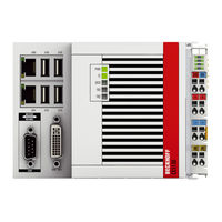
Beckhoff CX5140 Manual (88 pages)
CX51x0 series Embedded PC
Brand:
Beckhoff
| Category:
Industrial PC
| Size: 20 MB
Table of Contents
Table of Contents
3
1 Notes on the Documentation
5
Explanation of Symbols
6
Related Documents
7
Documentation Issue Status
7
2 For Your Safety
8
Intended Use
8
Staff Qualification
9
Safety Instructions
9
3 Transport and Storage
11
Table 1 Dimensions and Weight of the Individual Modules
11
4 Product Overview
12
Table 2 Available Optional Interfaces for the Cx51X0
12
Configuration of the Cx51X0 Embedded PC
13
Table 3 Legend for the Configuration
13
Fig. 1 Example: CX5140 Embedded PC
13
Name Plate
14
Table 4 Legend for the Name Plate
14
Fig. 2 Cx51X0 Name Plate
14
Types
15
Table 5 Cx51X0, Ordering Information for Software
15
Fig. 3 Nomenclature for the Cx51X0 Embedded PC
15
Architecture Overview
16
5 Description of the Interfaces
18
Usb (X100, X101, X102, X103)
18
Table 6 USB Interfaces (X100, X101, X102, X103), Pin Assignment
18
Fig. 4 USB Interfaces (X100, X101, X102, X103)
18
Fig. 5 USB Interface, Pin Numbering
18
Ethernet RJ45 (X000, X001)
19
Table 7 Ethernet Interface X000 and X001, Pin Assignment
19
Fig. 6 Ethernet Interface X000, X001
19
Fig. 7 Ethernet Interface, Pin Numbering
19
DVI-I (X200)
20
Table 8 DVI-I Interface X200, Pin Assignment
20
Table 9 DVI-I Cross, Pin Assignment
20
Table 10 DVI-I Interface X200, Resolution at the Monitor
20
Fig. 8 DVI-I Interface X200
20
Optional Interfaces
21
DVI-D (N010)
21
Table 11 DVI-D Interface X300, Pin Assignment
21
Table 12 DVI-D Interface X300, Resolution at the Monitor
21
Fig. 9 DVI-D Interface X300
21
Displayport (N011)
22
Table 13 Displayport, Pin Assignment
22
Table 14 Displayport X300, Resolution at the Monitor
22
Fig. 10 Displayport X300
22
Audio Interface (N020)
23
Table 15 Line in /Line out Jack Plugs, Pin Assignment
23
Fig. 11 Audio Interface X300, X301, X302
23
Fig. 12 Line in / Line out X300, X302 Jack Plugs
23
Fig. 13 MIC in X301 Jack Plug
23
Rs232 (N030)
24
Table 16 RS232 Interface X300, Pin Assignment
24
Fig. 14 RS232 Interface X300 with Pin Numbering
24
Rs422/Rs485 (N031)
25
Table 17 RS422/485 Interface, Pin Assignment
25
Table 18 Default Setting, RS485 Without Echo with End Point (Terminated)
25
Fig. 15 RS485 Interface X300 with Pin Numbering
25
Ethercat Slave (B110)
27
Table 19 Ethercat Slave Interface X300, Pin Assignment
27
Fig. 16 Ethercat Slave Interface X300
27
Fig. 17 Ethercat Slave LAN Interface, Pin Numbering
27
PROFIBUS (X310)
28
Table 20 PROFIBUS Interface X310, Pin Assignment
28
Table 21 Wire Colors of the PROFIBUS Line
28
Fig. 18 PROFIBUS Interface X310 with Pin Numbering
28
Canopen (X510)
29
Table 22 Canopen Interface X510, Pin Assignment
29
Fig. 19 Canopen Interface X510 with Pin Numbering
29
PROFINET RT (X930)
30
Table 23 PROFINET RT Interface, Pin Assignment
30
Fig. 20 PROFINET RT Interface X300
30
Fig. 21 PROFINET RT LAN Interface, Pin Numbering
30
6 Commissioning
31
Assembly
31
Note the Permissible Installation Positions
31
Fig. 22 Cx51X0 Embedded PC, Permitted Installation Position
31
Fig. 23 Cx51X0 Embedded PC, Invalid Installation Positions
32
Attaching on Mounting Rail
33
Microsd Card Installation and Removal
34
Cfast Card Installation and Removal
35
Installing Passive Ethercat Terminals
36
Fig. 24 Identifying a Passive Ethercat Terminal in Twincat
36
Fig. 25 Passive Ethercat Terminals, Permissible Installation
36
Fig. 26 Passive Ethercat Terminals, Invalid Installation
36
Connecting the Power Supply
37
Table 24 Legend for the Connection Example
37
Table 25 Required Wire Cross-Sections and Strip Lengths
38
Switching on
39
Switching off
39
7 Configuration
40
Windows Embedded Compact 7
40
Setting up the Audio Interface (N020)
40
Windows Embedded Standard 7 P
41
Identification of the Ethernet Interfaces (X000, X001)
41
Fig. 27 Windows 7, Identification of the Ethernet Interfaces (X000, X001) in the Network and Sharing Center
41
Fig. 28 Windows 7, Identification of the Ethernet Interfaces (X000, X001) in the Device Manager
41
Enabling Jumbo Frames
42
Set NIC Teaming
43
Restoring the Beckhoff Real-Time Driver
45
Windows 10 Iot Enterprise LTSB
46
Identification of the Ethernet Interfaces (X000, X001)
46
Fig. 29 Windows 10, Identification of the Ethernet Interfaces (X000, X001) in the Network and Sharing Center
46
Fig. 30 Windows 10, Identification of the Ethernet Interfaces (X000, X001) in the Device Manager
46
Enabling Jumbo Frames
47
Set NIC Teaming
48
Restoring the Beckhoff Real-Time Driver
50
Beckhoff Device Manager
51
Starting the Beckhoff Device Manager
51
Table 26 Access Data for the Beckhoff Device Manager on Delivery
51
Enabling a Remote Display
52
Twincat
53
Tree View
53
Table 27 Legend for the Tree View
53
Fig. 31 Cx51X0 Embedded PC in the Tree View of Twincat 3, with Attached Ethercat Terminals (Left) or Bus Terminals (Right)
53
Searching for Target Systems
54
Adding an Embedded PC
56
Configure the Serial Interface (N03X)
57
Configuring Ethercat Cable Redundancy
59
Table 28 Cable Redundancy, Hardware for Sample Configuration
59
Fig. 32 Smallest Possible Configuration for Ethercat Cable Redundancy
59
Using a Hardware Watchdog
61
1 Second UPS (Persistent Data)
63
BIOS Settings
64
Windows Write Filter
66
Fig. 33 FBWF Exception List, under Twincat 2 (Left) and Twincat 3
66
Fig. 34 UWF Exception List under Twincat 3
66
Table 29 Block Modes
67
Fb_S_Ups_Cx51X0
67
Mode and Status of the Function Block
69
Checking the Validity of the Variables
70
Systeminfotype
70
Plcappsysteminfo
72
9 Error Handling and Diagnostics
73
Diagnostic Leds
73
Power Supply Terminal Leds in K-Bus Mode
74
Table 30 K-Bus ERR LED, Fault Indication Sequence through the LED
74
Table 31 K-BUS ERR LED, Fault Description and Troubleshooting
75
Table 32 Description of the State Variable Values
76
Fig. 35 Status Variable for Error Handling and Diagnostics under Twincat
76
Power Supply Terminal Leds in K-Bus Mode
77
Faults
78
10 Care and Maintenance
79
Replace the Battery
79
Table 33 Technical Data of the Battery
79
11 Decommissioning
80
Removing Cables
80
Dismantling the Embedded PC
81
12 Technical Data
82
Table 34 Technical Data, Dimensions and Weights
82
Table 35 Technical Data, General Data
82
Table 36 Technical Data, I/O Terminals
82
Table 37 Technical Data, Environmental Conditions
83
Table 38 Technical Data, Graphic Specifications
83
Table 39 Technical Data, Interfaces
83
Table 40 Technical Data, Optional Interfaces
83
13 Appendix
84
Accessories
84
Table 41 Cfast Cards
84
Table 42 Microsd Cards
84
Table 43 Passive DVI-To-VGA Adaptor
84
Table 44 Spare Battery for CX Systems
84
Certifications
85
Support and Service
86
List of Tables
87
List of Figures
88
Beckhoff CX5140 Manual (95 pages)
Embedded-PC
Brand:
Beckhoff
| Category:
Desktop
| Size: 7 MB
Table of Contents
Table of Contents
3
1 Foreword
5
Notes on the Documentation
5
Safety Instructions
6
Documentation Issue Status
7
2 Product Overview
8
Intended Use
8
System Overview
9
CX5120 Technical Data
11
CX5130 Technical Data
12
CX5140 Technical Data
13
Types
14
Architecture Overview
16
Battery Compartment
18
Cfast Slot
20
Cfast Card
21
3 Seconds UPS
22
S-UPS: Capacitive One-Second UPS
22
Overview
24
FUNCTION_BLOCK Fb_S_Ups_Cx51X0
25
FUNCTION_BLOCK Fb_Nt_Quickshutdown
27
Functions
28
FUNCTION F_Getversiontcsups_Cx51X0
28
Data Types
29
4 Mounting and Wiring
30
Unpacking, Installation and Transport
30
Dimensions
31
Installation on the Mounting Rail
33
Power Supply
35
Installation of Passive Terminals at the Cx51X0 Power Supply Unit
37
DVI-I Port
38
USB Connections
40
LAN Connections
41
RS232 Connections (Cx51X0-N030)
43
RS422/RS485 Connections (Cx51X0-N031)
44
5 Commissioning/Configuration
46
BIOS Setup
46
Main
47
Advanced
49
Chipset
67
Security
72
Boot
73
Save & Exit
75
Ethercat Cable Redundancy
76
Operating Cx51X0-N03X with Twincat
80
Operation with Twincat2
80
Operation with Twincat3
82
Switching on and off
84
6 Error Handling and Diagnostics
85
Basic CPU Module
85
Leds on the Basic CPU Module
85
Leds of the Power Supply in K-Bus Mode
86
Leds of the Power Supply in E-Bus Mode
89
Faults
90
7 Decommissioning
91
Disassembly and Disposal
91
8 Appendix
93
Accessories
93
Certifications
94
Support and Service
95
Advertisement
Beckhoff CX5140 Manual (95 pages)
Embedded-PC
Brand:
Beckhoff
| Category:
Desktop
| Size: 22 MB
Advertisement
Related Products
Beckhoff CX5120
Beckhoff CX5130
Beckhoff CX56 0 Series
Beckhoff CX5620
Beckhoff CX5630
Beckhoff CX53 0 Series
Beckhoff CX5330
Beckhoff CX5340
Beckhoff CX52 0-N010 Series
Beckhoff CX2020
Beckhoff Categories
Touch terminals
Industrial PC
Control Unit
Industrial Equipment
Control Panel
More Beckhoff Manuals
Login
Sign In
OR
Sign in with Facebook
Sign in with Google
Upload manual
Upload from disk
Upload from URL