Table of Contents
Advertisement
Advertisement
Table of Contents

Related Manuals for Beckhoff CX51 0 Series


Summary of Contents for Beckhoff CX51 0 Series
- Page 1 Manual CX51x0 Embedded-PC Version: Date: 2016-05-18...
-
Page 3: Table Of Contents
Table of contents Table of contents 1 Foreword .............................. 5 Notes on the documentation...................... 5 Safety instructions .......................... 6 Documentation issue status...................... 7 2 Product overview............................ 8 Intended use ............................. 8 System overview.......................... 9 CX5120 Technical data ........................ 11 CX5130 Technical data ........................ 12 CX5140 Technical data ........................ - Page 4 Table of contents 5.3.1 Operation with TwinCAT2 .................... 80 5.3.2 Operation with TwinCAT3 .................... 82 Switching on and off ........................ 84 6 Error handling and diagnostics ...................... 85 Basic CPU module.......................... 85 6.1.1 LEDs on the basic CPU module .................. 85 6.1.2 LEDs of the power supply in K-bus mode................ 86 6.1.3 LEDs of the power supply in E-bus mode................ 89 Faults ..............................
-
Page 5: Foreword
EP0851348, US6167425 with corresponding applications or registrations in various other countries. ® EtherCAT is registered trademark and patented technology, licensed by Beckhoff Automation GmbH, Germany Copyright © Beckhoff Automation GmbH & Co. KG, Germany. The reproduction, distribution and utilization of this document as well as the communication of its contents to others without express authorization are prohibited. -
Page 6: Safety Instructions
All the components are supplied in particular hardware and software configurations appropriate for the application. Modifications to hardware or software configurations other than those described in the documentation are not permitted, and nullify the liability of Beckhoff Automation GmbH & Co. KG. Personnel qualification This description is only intended for trained specialists in control, automation and drive engineering who are familiar with the applicable national standards. -
Page 7: Documentation Issue Status
Foreword Documentation issue status Version Modifications Preliminary version First publication UL requirements added Values changed in chapter Seconds UPS Architecture overview added Revised description of the Diagnostic LEDs Note about driver support for serial port added Chapter Types reworked CX51x0 Version: 1.6... -
Page 8: Product Overview
Product overview Product overview Intended use The CX51x0 device series is a modular control system designed for top-hat rail installation. The system is scalable, so that the required modules can be assembled and installed in the control cabinet or terminal box as required. -
Page 9: System Overview
PLC, Motion Control, interpolation and visualization As a DIN rail IPC and in conjunction with the TwinCAT software from Beckhoff, the CX51x0 offers the same functionality as large Industrial PCs. In terms of PLC, up to four virtual IEC 61131 CPUs can be programmed with up to four tasks each, with a minimum cycle time of 50 μs. - Page 10 The complete programming of PLC, Motion Control and visualization is transferable to all PC controls from Beckhoff, which is reassuring in cases where it becomes apparent during a project that more processing power is required after all. In this case a system with higher performance can be used.
-
Page 11: Cx5120 Technical Data
Relative humidity 95 % no condensation Vibration/shock resistant Conforms to EN 60068-2-6 / EN 60068-2-27 EMC immunity/emission Conforms to EN 61000-6-2 / EN 61000-6-4 Protection class IP 20 Approvals TC3 performance class performance (40) Further Information: www.beckhoff.de/CX5100 CX51x0 Version: 1.6... -
Page 12: Cx5130 Technical Data
Relative humidity 95 % no condensation Vibration/shock resistant Conforms to EN 60068-2-6 / EN 60068-2-27 EMC immunity/emission Conforms to EN 61000-6-2 / EN 61000-6-4 Protection class IP 20 Approvals TC3 performance class performance (40) Further Information: www.beckhoff.de/CX5100 Version: 1.6 CX51x0... -
Page 13: Cx5140 Technical Data
Relative humidity 95 % no condensation Vibration/shock resistant Conforms to EN 60068-2-6 / EN 60068-2-27 EMC immunity/emission Conforms to EN 61000-6-2 / EN 61000-6-4 Protection class IP 20 Approvals TC3 performance class performance plus (50) Further Information: www.beckhoff.de/CX5100 CX51x0 Version: 1.6... -
Page 14: Types
Product overview Types The CPU module can be equipped with different hardware and software options: the operating systems are Windows Embedded Standard 7 in the 32-bit or 64-bit version. The TwinCAT automation software transforms a CX51x0 system into powerful PLC and Motion Control system that can be operated with or without visualization. - Page 15 Product overview Table 3: CX5140 (1.91 GHz 4 cores) Module Windows Windows TwinCAT 2 TwinCAT 2 TwinCAT 2 TwinCAT 3 operating Embedded Embedded TwinCAT PLC- NC-PTP- NC-I- system Standard 7 P Standard 7 P Runtime Runtime Runtime (32-Bit) (64-Bit) CX5140-0100 CX5140-0120 CX5140-0121 CX5140-0122 CX5140-0123...
-
Page 16: Architecture Overview
Product overview Architecture overview The Embedded PCs of the CX51x0 family all have the same architecture. This is described below. The CX51x0 Embedded PCs are based on the Intel Atom microarchitecture, which was developed by Intel. The CPUs used in the CX51x0 family are: ®... - Page 17 Product overview The interfaces (USB, DVI, and LAN ports) are standard interfaces. They can be used for operating devices that comply with the standard. The DVI-I port can be used to connect a VGA monitor via an adapter. If a breakout cable separating DVI and VGA is used, both types can be operated simultaneously.
-
Page 18: Battery Compartment
Attention Never open the battery or throw it into a fire. The battery cannot be recharged. Battery maintenance The battery must be replaced every 5 years. Spare batteries can be ordered from Beckhoff Sales under order number CX1900-0102. Note Version: 1.6... - Page 19 The use of alternative batteries would void the UL Listing. Panasonic batteries were certified as part of the UL Listing. The use of alternative batteries without consulting UL may invalidate the certification. Certified batteries can be ordered Note from Beckhoff Sales. CX51x0 Version: 1.6...
-
Page 20: Cfast Slot
Product overview CFast slot A CFast slot is located at the front. It enables the storage medium to be replaced. In the basic module this should only be done in switched-off state, otherwise the system may crash. The CFast card can be removed from the module for maintenance. -
Page 21: Cfast Card
In order to store data in a non-volatile manner, they must be stored on the CFast card. Using CFast cards We strongly recommend that only CFast cards supplied by Beckhoff Automation GmbH & Co. KG should be used. These are industry-standard CFast cards with enhanced number Note of write/read cycles and an advanced temperature range (-25 °C to +85 °C). -
Page 22: Seconds Ups
Seconds UPS Seconds UPS S-UPS: capacitive one-second UPS The CX51x0 family features a built-in capacitive one-second UPS. It ensures a safe storage of the persistent application data on the Compact Flash card. Up to 1 MB of persistent data can be saved. The UPS can be switched on and off via the BIOS. Under the menu: Advanced ->... - Page 23 TwinCAT offers special function blocks for integrating the S-UPS into a PLC program. These are described below. From TwinCAT 2.11R3 Build 2247 or TwinCAT 3.1 Build 4018 the required library is integrated in the installation. For older versions the library: http://infosys.beckhoff.com/content/1033/CX51x0_HW/Resources/rar/1941420683.rar has to be copied into the TwinCAT library directory. CX51x0...
-
Page 24: Overview
Seconds UPS Overview The library TcSUPS_CX51x0.lib includes functions and function blocks required for controlling the one- second UPS. See project example: http://infosys.beckhoff.com/content/1033/CX51x0_HW/Resources/pro/1937303563.pro Function blocks Name Description FB_S_UPS_CX51x0 Block for controlling the one-second UPS FB_NT_QuickShutdown Internal block for QuickShutdown, used by the FB_S_UPS. -
Page 25: Function_Block Fb_S_Ups_Cx51X0
If the EWF is used, the TwinCAT\Boot folder must be located on an unprotected partition (see in the registry: HKEY_LOCAL_MACHINE\SOFTWARE\Beckhoff\TwinCAT\System\BootPrjPath). If the FBWF is used, must the TwinCAT\Boot folder must be excluded from the protection (see Beckhoff FBWF Manager, Exclusion Settings). - Page 26 Seconds UPS ePersistentMode : E_PersistentMode := SPDM_2PASS; (* mode for writing persistent data *) tRecoverTime : TIME := T#10s; (* ON time to recover from short power failure in mode eS- UPS_WrPersistData_NoShutdown/eSUPS_CheckPowerStatus *) END_VAR E_S_UPS_Mode sNetID : AmsNetID of the controller. iPLCPort : Port number of the PLC runtime system (AMSPORT_R0_PLC_RTS1 = 801, AMSPORT_R0_PLC_RTS2 = 811, AMSPORT_R0_PLC_RTS3 = 821, AMSPORT_R0_PLC_RTS4 = 831).
-
Page 27: Function_Block Fb_Nt_Quickshutdown
Seconds UPS 3.2.2 FUNCTION_BLOCK FB_NT_QuickShutdown The function block FB_NT_QuickShutdown can be used to trigger an immediate reboot, without stopping TwinCAT or the Windows operating system. Attention: Loss of data The function block FB_NT_QuickShutdown is used internally by FB_S_UPS_CX51x0. It must not be used independently, because this could result in data loss! Attention FUNCTION_BLOCK FB_NT_QuickShutdown VAR_INPUT... -
Page 28: Functions
Seconds UPS Functions 3.3.1 FUNCTION F_GetVersionTcSUPS_CX51x0 This function can be used to read PLC library version information. FUNCTION F_GetVersionTcSUPS_CX51x0 : UINT VAR_INPUT nVersionElement : INT; END_VAR nVersionElement : Version element to be read. Possible parameters: • 1 : major number •... -
Page 29: Data Types
Seconds UPS Data Types 3.4.1 TYPE E_S_UPS_Mode eSUPS_WrPersistData_Shutdown: write persistent data and then QuickShutdown eSUPS_WrPersistData_NoShutdown: write persistent data only (no QuickShutdown) eSUPS_ImmediateShutdown: QuickShutdown only (no writing of persistent data) eSUPS_CheckPowerStatus: determine status only (neither write persistent data nor QuickShutdown) Prerequisites Development environment Target plat- Hardware... -
Page 30: Mounting And Wiring
5. Check the contents for visible shipping damage. 6. If you notice any shipping damage or inconsistencies between the contents and your order, you should notify Beckhoff Service. Danger of damage to the device! During transport in cold conditions, or if the device is subjected to extreme temperature dif- ferences, condensation on and inside the device must be avoided. -
Page 31: Dimensions
Mounting and wiring Dimensions Dimensions: CX5120-01xx: CX5130-01xx: CX5140-01xx: CX51x0 Version: 1.6... - Page 32 Mounting and wiring Version: 1.6 CX51x0...
-
Page 33: Installation On The Mounting Rail
Mounting and wiring Installation on the mounting rail Snapping onto the mounting rail The CX51x0 can simply be snapped onto the mounting rail. The bar clips are inserted on the top side and underside Then simply position the block on the mounting rail and push it slightly until it engages on the right-hand side. - Page 34 Mounting and wiring Incorrect installation positions The CX51x0 system must not be operated vertically on the top-hat rail. A vertical position would lead to insufficient CPU ventilation, since the ventilation openings are located on the top and bottom of the housing. Installation of the system on its side would also lead to inadequate ventilation.
-
Page 35: Power Supply
Mounting and wiring Power supply This power supply unit is equipped with an I/O interface, which permits connection of the Beckhoff Bus Terminals. The power is supplied via the upper spring-loaded terminals labelled “24V” and “0”V. The CX system is supplied with 24 V DC (-15 %/+20%) via the internal bus and the Bus Terminals. The dielectric strength of the power supply unit is 500 V . - Page 36 Mounting and wiring Wire cross section 0,5 ... 2.5 mm AWG 20 … AWG 14 Strip length 8 ... 9 mm 8.38 mm If the power supply unit is connected correctly and the power supply is switched on, the two upper LEDs in the terminal prism are green.
-
Page 37: Installation Of Passive Terminals At The Cx51X0 Power Supply Unit
Mounting and wiring Installation of passive terminals at the CX51x0 power supply unit Note on the mounting of passive terminals EtherCAT Bus Terminals (ELxxxx/ESxxxx) that do not actively participate in data exchange within the Bus Terminal block are called passive terminals. These terminals can be recog- Note nized by their lack of power consumption from the E-Bus. -
Page 38: Dvi-I Port
The DVI-I interface transfers digital data and is suitable for connecting a digital or analog display. The resolution at the display or the Beckhoff Control Panel depends on the distance from the display device. The maximum distance is 5 m. Beckhoff offers various Panels with an integrated “DVI extension”. These make a cable length of up to 50 meters possible. - Page 39 Mounting and wiring Resolution at the monitor Resolution in pixels Distance of the interface from the monitor 1920 x 1200 1920 x 1080 1600 x 1200 1280 x 1024 1024 x 768 800 x 600 640 x 480 The Embedded PC also supports higher resolutions according to the DVI standard. A maximum resolution of 2560 x 1440 pixels can be set on the Embedded PC.
-
Page 40: Usb Connections
Mounting and wiring USB connections USB interface (X100 / X101 / X102 / X103): The CX51x0 units have 4 independent USB interfaces for connecting keyboards, mice, touchscreens and other input or data storage devices. Attention is thereby to be paid to the power consumption of the individual devices: No more than 500 mA can be output per port. -
Page 41: Lan Connections
Mounting and wiring LAN connections LAN interface (X000/ X001) The CX51x0 systems have two independent LAN interfaces. Both ports are able to operate at speeds of 10 / 100 / 1000 Mbit. The LEDs on the left-hand sides of the RJ45 sockets indicate the status of the LAN connection. - Page 42 Mounting and wiring Independence of the ports The two ports are independent from each other. In contrast to the CX systems CX1020 and CX9000 systems, no switch is integrated. For a line topology an additional switch is re- Note quired. The independent ports can be configured in different ways: In delivery state the up- per port (1) is configured as GB IT port, the lower port (2) is configured for EtherCAT com- munication.
-
Page 43: Rs232 Connections (Cx51X0-N030)
Mounting and wiring RS232 connections (CX51x0-N030) The CX51x0-N030 system interface provides an RS232 interface, COM1 (X300). It is implemented on a 9- pole Sub-D pin contact strip. If more than one interface is required, the system can be extended with the required number of serial interfaces using the terminal bus (K- or E-bus) and Bus Terminals (KL/EL6001). -
Page 44: Rs422/Rs485 Connections (Cx51X0-N031)
Mounting and wiring 4.10 RS422/RS485 connections (CX51x0-N031) The CX51x0-N031 system interface provides an RS422 or RS 485 interface, COM1 (X300). It is implemented on a 9-pole Sub-D socket strip. If more than one interface is required, the system can be extended with the required number of serial interfaces using the terminal bus (K- or E-bus) and Bus Terminals (KL/EL6001). - Page 45 Mounting and wiring Changing the interface parameters If other parameters are required than the set parameters, please order the required config- uration: Note - CX51x0-N031-0001 RS485 with echo, end point (with termination) - CX51x0-N031-0002 RS485 without echo, stub (without termination) - CX51x0-N031-0003 RS485 with echo, stub (without termination) - CX51x0-N031-0004 RS422 full duplex end point (with termination) Driver support for interface...
-
Page 46: Commissioning/Configuration
Changes in the BIOS settings may only be implemented by appropriately trained staff. The CX51x0 systems are delivered by Beckhoff Automation GmbH & Co. KG in a precon- Attention figured state and are therefore operational! The BIOS settings should only be modified by appropriately trained staff. -
Page 47: Main
Commissioning/Configuration 5.1.1 Main Aptio Setup Utility - Copyright (C) American Megatrends, Inc. Board Information Set the Date. Use Tab to switch between Date elements. Board CX51x0 Revision Bios Version 0.23 CPU configuration MIcrocode Patch BayTrail SoC B3 Stepping Memory Information Total Memory 2048 MB (DDR3L) →... - Page 48 Commissioning/Configuration Setting the system date System time Options: • hh … hours • mm … minutes • ss … seconds Setting the system time Version: 1.6 CX51x0...
-
Page 49: Advanced
Commissioning/Configuration 5.1.2 Advanced Aptio Setup Utility - Copyright (C) American Megatrends, Inc. Power-Supply Type [AT] Select the Type of the Power Supply: AT/ATX ► ACPI Settings ► Serial Port Console Redirection ► CPU Configuration ► PPM Configuration ► SATA Configuration ►... - Page 50 Commissioning/Configuration 5.1.2.2 Serial Port Console Redirection Aptio Setup Utility - Copyright (C) American Megatrends, Inc. COM0 (Disabled) Legacy Console Redirection Settings Console Redirection Port Is Disabled COM1 (Disabled) → ←: Select Screen ↑ ↓: Select Item Console Redirection Port Is Disabled Enter: Select ►...
- Page 51 Commissioning/Configuration 5.1.2.3 CPU Configuration Aptio Setup Utility - Copyright (C) American Megatrends, Inc. CPU Configuration Disabled for Windows XP ► Socket 0 CPU Information ► CPU Thermal Configuration CPU Speed 1467 MHz 64-bit Supported Limit CPUID Maximum [Disabled] Execute Disable Bit [Enabled] Intel Virtualization Technology [Enabled]...
- Page 52 Commissioning/Configuration Power Technology Options: Disabled / Energy Efficient / Custom Defines the behavior of the energy saving functions. Disabled > switched off (required for real-time operation) Energy Efficient > the CPU controls the individual systems, Custom > user-defined energy-saving settings (only for expert users). Version: 1.6 CX51x0...
- Page 53 Commissioning/Configuration 5.1.2.4 PPM Configuration Aptio Setup Utility - Copyright (C) American Megatrends, Inc. PPM Configuration Enable/Disable CPU C state Report [Disabled] → ←: Select Screen ↑ ↓: Select Item S01X [Disabled] Enter: Select +/-: Change Options F1: General Help F2: Previous Values F3: Optimized Defaults F4: Save &...
- Page 54 Commissioning/Configuration 5.1.2.5 SATA Configuration Aptio Setup Utility - Copyright (C) American Megatrends, Inc. SATA Configuration Serial-ATA (SATA) [Enabled] SATA Test Mode [Disabled] SATA Speed Support [Gen2] SATA ODD Port [No ODD] SATA Mode [AHCI] Serial ATA Port 0 [Enabled] Hot Plug [Disabled] Serial ATA Port 1 [Enabled]...
- Page 55 Commissioning/Configuration Hot Plug Options: Enabled / Disabled Activates or deactivates the option to add or swap components during operation. CX51x0 Version: 1.6...
- Page 56 Commissioning/Configuration 5.1.2.6 Network Stack Aptio Setup Utility - Copyright (C) American Megatrends, Inc. Network Stack [Disable] Enable/Disable UEFI network stack → ←: Select Screen ↑ ↓: Select Item Enter: Select +/-: Change Options F1: General Help F2: Previous Values F3: Optimized Defaults F4: Save &...
- Page 57 Commissioning/Configuration 5.1.2.7 Power Controller Options Aptio Setup Utility - Copyright (C) American Megatrends, Inc. Bootloader Version 1.00-23 WatchDogTimer Mode Firmware Version 1.00-77 Mainboard Serial No 120003414250178 Mainboard Prod. Date (Week.Year) 44.14 Mainboard BootCount 4711 Mainboard Operation Time 1224min (20h) Voltage (Min/Max) 5.00V / 5.20V Temperature (Min/Max) 15 °C / 63 °C...
- Page 58 Commissioning/Configuration WatchDog Timer Mode Options: Compatibility Mode / Normal Mode Defines the watchdog timer mode. SUPS Enable Options: Enable / Disable Switches the SUPS on or off. Hold USB Options: Enable / Disable Switches off the power supply for the USB ports in UPS mode. Delay Options: 0..255 seconds Start delay with which the SUPS is loaded.
- Page 59 Commissioning/Configuration 5.1.2.8 CSM Configuration Aptio Setup Utility - Copyright (C) American Megatrends, Inc. Compatibility Support Module Configuration WatchDogTimer Mode CSM Support [Enabled] CSM16 Module Version 07.76 GateA20 Active [Upon Request] Option ROM Messages [Force BIOS] Boot option filter [UEFI and Legacy] Option ROM execution →...
- Page 60 Commissioning/Configuration Other PCI devices Options: Do not launch / UEFI / Legacy Specifies the start options for the PCI ROM. Version: 1.6 CX51x0...
- Page 61 Commissioning/Configuration 5.1.2.9 SDIO Configuration Aptio Setup Utility - Copyright (C) American Megatrends, Inc. SDIO Access Mode [Auto] Auto Option: Access SD device in DMA mode if controller supports it, otherwise in PIO mode. DMA Option: Access SD device in DMA mode.
- Page 62 Commissioning/Configuration 5.1.2.10 USB Configuration Aptio Setup Utility - Copyright (C) American Megatrends, Inc. USB Configuration USB Module Version 8.11.02 USB Devices: 1 Keyboard, 1 Mouse, 1 Hubs Legacy USB Support [Enabled] XHCI Hand-off [Enabled] EHCI Hand-off [Disabled] USB Mass Storage Driver Support [Enabled] Port 60/64 Emulation [Enabled] →...
- Page 63 Commissioning/Configuration USB Transfer time-out: Options: 5 sec / 10 sec / 20 sec Defines the timeout time for the control, bulk and interrupt transfer Device reset time-out Options: 10 sec / 20 sec / 30 sec / 40 sec Defines the timeout time for the USB mass storage device. Device Power-up delay Options: Auto / Manual Defines the permissible delay until a device has registered with the host controller.
- Page 64 Commissioning/Configuration 5.1.2.11 Security Configuration Aptio Setup Utility - Copyright (C) American Megatrends, Inc. Intel(R) TXE Configuration Send EOP Message Before Enter OS [Enabled] TXE HMFRPO [Disabled] TXE Firmware Update [Enabled] TXE EOP Message [Enabled] TXE Unconfiguration Perform → ←: Select Screen ↑...
- Page 65 Commissioning/Configuration 5.1.2.12 Intel(R) I210 Gigabit Network Connection Aptio Setup Utility - Copyright (C) American Megatrends, Inc. ► NIC Configuration Identify the physical network port by blinking the associated LED. Flashing LEDs UEFI Driver Intel(R) PRO/1000 6.4.13 Adapter PBA Intel i210 Device Name Intel(R) I210 Gigabit Chip Type...
- Page 66 Commissioning/Configuration 5.1.2.12.1 NIC Configuration Aptio Setup Utility - Copyright (C) American Megatrends, Inc. Link Speed [Auto Negotiated] Enable/Disable UEFI network stack Wake on LAN [Enabled] → ←: Select Screen ↑ ↓: Select Item Enter: Select +/-: Change Options F1: General Help F2: Previous Values F3: Optimized Defaults F4: Save &...
-
Page 67: Chipset
Commissioning/Configuration 5.1.3 Chipset Aptio Setup Utility - Copyright (C) American Megatrends, Inc. ►North Bridge ►South Bridge → ←: Select Screen ↑ ↓: Select Item Enter: Select +/-: Change Options F1: General Help F2: Previous Values F3: Optimized Defaults F4: Save & Exit ESC: Quit Version 2.17.1246. - Page 68 Commissioning/Configuration High Precision Timer Options: Enabled / Disabled Activates or deactivates the “High Precision Event Timer”. This enables the operating system to allocate certain timers to specific applications. Restore AC Power Loss Options: Power on / Power Off / Last State Defines the measures that are executed by the system after a power failure.
- Page 69 Commissioning/Configuration Azalia HDMI Codec Options: Enabled / Disabled Activates or deactivates the HDMI Audiocodec. HDMI Port B Options: Enabled / Disabled Activates or deactivates HDMI port B. HDMI Port C Options: Enabled / Disabled Activates or deactivates HDMI port C. CX51x0 Version: 1.6...
- Page 70 Commissioning/Configuration 5.1.3.1.2 USB Configuration Aptio Setup Utility - Copyright (C) American Megatrends, Inc. USB Configuration USB Mode [XHCI] USB2 Link Power Management [Enabled] USB Per Port Control [Disabled] → ←: Select Screen ↑ ↓: Select Item Enter: Select +/-: Change Options F1: General Help F2: Previous Values F3: Optimized Defaults...
- Page 71 Commissioning/Configuration 5.1.3.1.3 PCI Express Configuration Aptio Setup Utility - Copyright (C) American Megatrends, Inc. PCI Express Configuration PCI Express Port 0 is assigned to LAN 1 PCI Express Port 1 is assigned to LAN 2 PCI Express Port 2 is assigned to CCAT →...
-
Page 72: Security
Commissioning/Configuration 5.1.4 Security Aptio Setup Utility - Copyright (C) American Megatrends, Inc. Password Description Minimum Length Maximum Length Administrator Password Secure Boot menu → ←: Select Screen ↑ ↓: Select Item Enter: Select +/-: Change Options F1: General Help F2: Previous Values F3: Optimized Defaults F4: Save &... -
Page 73: Boot
Commissioning/Configuration 5.1.5 Boot Aptio Setup Utility - Copyright (C) American Megatrends, Inc. Boot Configuration Setup Prompt Timeout Bootup NumLock State [On] Boot mode select [LEGACY] FIXED BOOT ORDER Priorities Boot Option #1 [Service Stick] Boot Option #2 [CFast/SSD] Boot Option #3 [Hard Disk:] Boot Option #4 [CD/DVD]... - Page 74 Commissioning/Configuration Boot Option #n (n={1..11}) Options: Service Stick / CFast/SSD / Hard Disk / CD/DVD / USB Stick / USB Floppy / USB Hard Disk / USB / CD/DVD / Network / USB LAN / OSLoader The boot option defined as #1 has the highest priority, followed by the second, third, etc. priority. Version: 1.6 CX51x0...
-
Page 75: Save & Exit
Commissioning/Configuration 5.1.6 Save & Exit Aptio Setup Utility - Copyright (C) American Megatrends, Inc. Save Changes and Reset Reset the system after saving the changes Discard Changes and Reset Restore Optimized Defaults → ←: Select Screen ↑ ↓: Select Item Enter: Select +/-: Change Options F1: General Help... -
Page 76: Ethercat Cable Redundancy
Minimum requirements: 1. EtherCAT redundancy supplement 2. EK1110 (Bus extension) 3. EK1100 (Bus Coupler) The supplement product on the Beckhoff website at http://download.beckhoff.com/download/Software/TwinCAT/TwinCAT2/Supplement/ TwinCAT_EtherCAT_Redundancy/Install/TcEcRedundancy.exe can be downloaded. The required license key can be ordered from our sales division. The required couplers are ordered together with the other hardware. - Page 77 It applies to connections between the individual stations (controllers, Note couplers and drives). Failures of individual terminals are not covered. Further details can be found in the “Beckhoff Information System" under EtherCAT cable redundancy. Cases of failure The two possible failures are described in the example below.
- Page 78 Commissioning/Configuration The interruption is indicated by "LNK_MIS B" and "LNK_MIS A". The next example shows a failure of the "return line": In this case the second cable is faulty. The terminals at the coupler continue to run without malfunction. The System Manager indicates the behavior as follows: Version: 1.6 CX51x0...
- Page 79 Commissioning/Configuration The interruption is indicated by "LNK_MIS C" at coupler EK1100. The EtherCAT ring is expandable. The number of devices in the ring is controlled by licenses: up to 250, up to 1000, more than 1000. A master is only able to bridge one failure. In the event of two failures the ring components will continue to run up to the breaking points.
-
Page 80: Operating Cx51X0-N03X With Twincat
Commissioning/Configuration Operating CX51x0-N03x with TwinCAT The procedure for commissioning the CX51x0-N03x with serial interface under TwinCAT differs from that for other Embedded PCs. In order to avoid configuration errors, the procedure for adding and configuring the CX51x0 in TwinCAT is described below. The description applies to TwinCAT from the following version: Software Version... - Page 81 Commissioning/Configuration 5. Select the option PCI/PCIe device. If the option Onboard/ISA device is already selected, the option PCI/PCIe device is greyed out and cannot be selected. The option PCI/PCIe device can be re-enabled as follows: 6. Click on Search. The window Device Found At appears. 7.
-
Page 82: Operation With Twincat3
Commissioning/Configuration 5.3.2 Operation with TwinCAT3 Once the CX was selected as target system, the CX with serial interface can be added to the tree view under TwinCAT. Prerequisites for this step: • A scanned and selected target system. Add the CX51x0-N03x as follows: 1. - Page 83 Commissioning/Configuration 5. Under the Serial Port tab, select the option PCI/PCIe Device. The serial interface of the CX51x0 is shown under Port:. If the option Onboard/ISA device is already selected, the option PCI/PCIe device is greyed out and cannot be selected. The option PCI/PCIe device can be re-enabled as follows: 6.
-
Page 84: Switching On And Off
Commissioning/Configuration Switching on and off Switching on The power supply for the basic CPU module comes from the power supply unit. The basic CPU module starts automatically when the power supply unit is connected to the mains. Switching on for the first time When you switch on the PC for the first time, the pre-installed operating system (optional) will be started. -
Page 85: Error Handling And Diagnostics
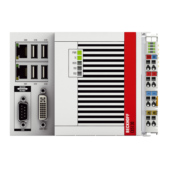
Error handling and diagnostics Error handling and diagnostics Basic CPU module 6.1.1 LEDs on the basic CPU module Display Meaning Power supply The power LED lights green if the device is connected to a power supply unit and the unit is switched on. -
Page 86: Leds Of The Power Supply In K-Bus Mode
Error handling and diagnostics 6.1.2 LEDs of the power supply in K-bus mode After switching on, the power supply immediately checks the connected Bus Terminal configuration. Error- free start-up is signalled by the red "I/O ERR” LED being extinguished. If the “I/O ERR” LED blinks, an error in the area of the terminals is indicated. - Page 87 Error handling and diagnostics LEDs for K-bus diagnostics Error code Error code argu- Description Remedy ment Persistent, continuous EMC problems - Check power supply for flashing overvoltage or undervoltage peaks - Implement EMC measures If a K-Bus error is present, it can be localized by a restart of the power supply (by switching it off and then on again)
- Page 88 Error handling and diagnostics K-bus state The K-bus status is saved in the state byte (see fig. K-bus interface “1”). If the value is 0 the K-bus is operating synchronously and without errors. If the value is <> ”0” there may be a fault, or it may only be an indication that the K-bus cycle is longer than the task, in which case it would no longer by synchronous with the task.
-
Page 89: Leds Of The Power Supply In E-Bus Mode
Error handling and diagnostics 6.1.3 LEDs of the power supply in E-bus mode After switching on, the power supply immediately checks the connected Bus Terminal configuration. In the E- Bus mode the “L/A” led lights up. It starts blinking when there is traffic on the bus. Display Meaning Us 24 V... -
Page 90: Faults
6. Any components / software used The quickest response will come from support / service in your country. Therefore please contact your regional contact. For details please refer to our website at www.beckhoff.de or ask your distribution partner. Version: 1.6... -
Page 91: Decommissioning
Decommissioning Decommissioning Disassembly and disposal A CX51x0 hardware configuration is dismantled in 2 stages: 1. Switching off and disconnecting the power supply Before removing a CX51x0 system, the system must be switched off and the power supply must be disconnected. 2. - Page 92 Do not use force to open the device! Opening the module housing by force would destroy it. The devices may only be opened by Beckhoff service personnel. Attention Disposal The device must be fully dismantled in order to dispose of it.
-
Page 93: Appendix
Appendix Appendix Accessories Table 4: CFast cards with first order CX20x0 Order number Description CX2900-0029 8 GB CFast card, SLC Flash, extended temperature range, instead of 4 GB CFast card CX2900-0031 16 GB CFast card, SLC Flash, extended temperature range, instead of 4 GB CFast card CX2900-0033 16 GB CFast card, SLC Flash, extended temperature range, instead of 8 GB... -
Page 94: Certifications
All products of the Embedded PC family are CE, UL and GOST-R certified. Since the product family is continuously developed further, we are unable to provide a full listing here. The current list of certified products can be found at www.beckhoff.com. FCC Approvals for the United States of America... -
Page 95: Support And Service
Beckhoff's branch offices and representatives Please contact your Beckhoff branch office or representative for local support and service on Beckhoff products! The addresses of Beckhoff's branch offices and representatives round the world can be found on her internet pages: http://www.beckhoff.com You will also find further documentation for Beckhoff components there.
Need help?
Do you have a question about the CX51 0 Series and is the answer not in the manual?
Questions and answers