Agilent Technologies 7697A Advanced Operation Manual
Headspace sampler
Hide thumbs
Also See for 7697A:
- Troubleshooting manual (92 pages) ,
- Operation manual (88 pages) ,
- Installation and startup manual (74 pages)
Table of Contents
Advertisement
Quick Links
Advertisement
Table of Contents

Related Manuals for Agilent Technologies 7697A


Summary of Contents for Agilent Technologies 7697A
- Page 1 Agilent 7697A Headspace Sampler Advanced Operation Agilent Technologies...
- Page 2 A CAUTION notice denotes a hazard. It prior agreement and written consent from permitted by applicable law, Agilent calls attention to an operating Agilent Technologies, Inc. as governed by disclaims all warranties, either express procedure, practice, or the like that, if United States and international copyright...
-
Page 3: Table Of Contents
The Keypad Headspace Analysis Headspace techniques Static headspace sampling techniques How the 7697A Headspace Sampler Works How the HS Processes a Sample Vial How the HS Equilibrates a Vial How the HS Pressurizes a Vial Fill at flow to pressure... - Page 4 Carrier Purge time and flow Other parameters Developing and Improving the Method Using parameter increment Vial size Vial shaking Sample loop size Pressurizing the vial Filling the sample loop Extraction mode Sequence Actions Types of sequence issues handled Available actions Sequence actions and data systems Optimizing Throughput Setting Up for a New Method...
- Page 5 To program an instrument schedule Options Calibration To calibrate the atmospheric pressure sensor To calibrate the tray To calibrate the gas sensors Communication To set the LAN address at the keyboard To use a DHCP server Keyboard and Display Early Maintenance Feedback What is Early Maintenance Feedback? To Set Up EMF for Use To Set a Limit for a Counter...
- Page 6 Advanced User Guide...
- Page 7 Agilent 7697A Headspace Sampler Advanced Operation Introduction About This Manual The Keypad Headspace Analysis This chapter introduces the Agilent 7697A Headspace Sampler and some basic concepts of headspace analysis. Agilent Technologies...
-
Page 8: Introduction
Introduction About This Manual This manual supplements the Operation guide. Use this manual as a resource when developing a method. It contains reference information, concepts, and procedures about: • Headspace theory • Theory of operation for the headspace sampler • Advanced functionality •... -
Page 9: The Keypad
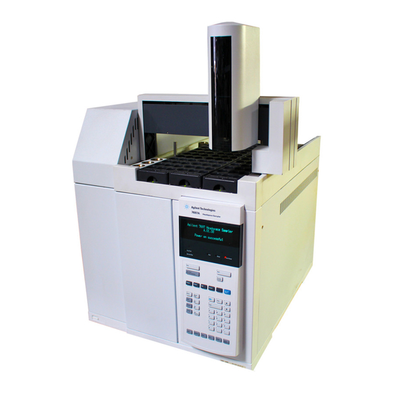
Introduction The Keypad This manual describes the functionality of the Agilent 7697A Headspace Sampler when operating primarily in standalone mode, using the keypad. Most information relates to the parameters available from the instrument keypad, shown in Figure 1 below. Figure 1... - Page 10 Introduction • More flexible sequencing If using a data system, see the data system help for more details. Connect to the HS instrument, open the method editor, and click the help icon ( ) or press F1. Advanced Operation...
-
Page 11: Headspace Analysis
Introduction Headspace Analysis Headspace analysis is a technique for analyzing volatile organic compounds using gas chromatography. Headspace analysis samples the ambient volume above a sample matrix, where the volatile compounds exist in gaseous form at predictable levels. Headspace analysis is useful for situations where: •... -
Page 12: Static Headspace Sampling Techniques
Introduction Static headspace sampling: This technique uses a closed sample container and a sampling system. After placing the sample matrix into the sealed sampling vial, the sample matrix is heated for a specified time, during which the vial can also be agitated (shaken) to help drive volatile compounds from the matrix and into the headspace volume. - Page 13 Pressure transfer system Valve and loop systems The valve and loop system, as used in the 7697A, also heats and agitates the vial for a specified time. However, the Agilent system uses a sample loop of known size to collect the sample.
- Page 14 Introduction 6 port valve Sample probe Transfer line Sample loop Vial Carrier gas pressurization gas Vial pressurization Sample probe Carrier gas Vent Sample loop filling Sample probe Carrier gas Vent Injection Figure 3 Valve and loop system sampling and injection stages Advanced Operation...
-
Page 15: How The 7697A Headspace Sampler Works
How the HS Pressurizes a Vial How the HS Fills the Sample Loop (Extracts a Sample) Types of HS Extractions and Injections How the HS Reduces Carryover This chapter describes the basic theory behind the 7697A headspace sampler. Agilent Technologies... -
Page 16: How The Hs Processes A Sample Vial
Lift vial onto sample probe. Lower vial into carousel. Figure 4 Basic 7697A HS vial process flow, 12 vial model Figure 5 shows the workflow for a vial processed by the 111 vial model HS (with tray). Advanced Operation... - Page 17 Lift vial onto sample carousel. probe. Figure 5 Basic 7697A HS vial process flow, 111 vial model The major differences in processing between the two models are: • Tray robotic arm moves vials to and from loading stations • 111 vial model uses a 12 vial oven that can process more than one vial at a time •...
-
Page 18: How The Hs Equilibrates A Vial
How the 7697A Headspace Sampler Works How the HS Equilibrates a Vial The 7697A HS with tray has a vial oven that can equilibrate up to 12 vials (depending on model) at temperatures from ambient + 5 °C up to 300 °C. In addition, the oven can shake the vials at 9 different acceleration levels. -
Page 19: How The Hs Pressurizes A Vial
How the 7697A Headspace Sampler Works How the HS Pressurizes a Vial All 7697A HS provide several techniques for pressurizing the sample vial. In addition to simply heating the vial, which may generate enough internal pressure on its own, the HS can provide additional gas to help with extraction. -
Page 20: Fill With Constant Volume
How the 7697A Headspace Sampler Works Fill with constant volume In this mode, the HS pressurizes the sample vial with a specified volume of carrier gas, then maintains the resultant pressure for the specified hold time. This mode is useful if you need to calculate the exact molar amounts of sample and carrier gas in the vial or sample loop. -
Page 21: How The Hs Fills The Sample Loop (Extracts A Sample)
How the 7697A Headspace Sampler Works How the HS Fills the Sample Loop (Extracts a Sample) After the vial is pressurized and has stabilized, the HS will perform the specified extractions. The six port valve switches, allowing the pressurized sample to vent through the sample loop. -
Page 22: Types Of Hs Extractions And Injections
How the 7697A Headspace Sampler Works Types of HS Extractions and Injections The 7697A HS can extract and inject sample once or multiple times per vial. The HS provides a selection for extraction type as an advanced function. Figure 8... -
Page 23: Standard Extraction
How the 7697A Headspace Sampler Works PS - Pressure sensor Vial pressurization gas FS - Flow sensor SV - Switching valve Vent Carrier gas PV - Proportional valve Flow control module Six port valve Sample loop Transfer line Figure 9... -
Page 24: Multiple Headspace Extractions
How the 7697A Headspace Sampler Works from it according to the method parameters. See Figure 8 Figure 9. After any sample loop equilibration, the HS six port valve switches to the inject position, the HS injects the sample, and the HS sends a Start command to the GC. At the same time, the HS vents residual pressure from the vial (optional). -
Page 25: Venting Residual Vial Pressure
How the 7697A Headspace Sampler Works loop equilibration, the HS six port valve switches to the inject position, and the HS injects the sample into the GC. The HS does not send a Start command to the GC. After the inject time elapses, the six port valve returns to its original position. -
Page 26: How The Hs Reduces Carryover
How the 7697A Headspace Sampler Works How the HS Reduces Carryover The 7697A HS provides two special features to reduce carryover. • After each vial, the HS purges the sample loop and sample probe with a high flow of vial pressurization gas, as defined in the method. -
Page 27: Method Development
Optimizing Throughput Setting Up for a New Method This chapter provides details and information about method parameters. This information is intended to help a method developer improve a method’s performance using the features of the 7697A headspace sampler. Agilent Technologies... -
Page 28: Overview
This chapter describes techniques to create and refine a method, using the available method parameters and method features of the 7697A HS. It describes all the method parameters available, and discusses how various parameters impact an analysis. This chapter assumes basic familiarity... -
Page 29: Consider The Sample And Matrix
Method Development Consider the Sample and Matrix The first step in developing the method is to understand the sample and matrix. Theory of headspace analysis The equations describing headspace theory derive from three physical laws associated with vapor pressure, partial pressures, and the relationship between vapor pressure of an analyte above a solution and the concentration of that analyte in the solution. -
Page 30: Impact Of K And Phase Ratio
Method Development Rearranging provides: where: K is the partition coefficient (or distribution coefficient), at equilibrium is also called the phase ratio The equation shows two important points: • For consistent results, the ratio V must remain constant. This means that the sample amount and vial size need to be kept the same. - Page 31 Where K is small, reducing the phase ratio will produce a higher concentration of analyte in the headspace volume. The 7697A can use a variety of sample vials. Select a sample vial and sample amount to create a higher concentration of analyte.
- Page 32 Where K is small, reducing the phase ratio will produce a higher concentration of analyte in the headspace volume. The 7697A can use a variety of sample vials. Select a sample vial and sample amount to create a higher concentration of analyte.
-
Page 33: Consider The Gc Inlet
Method Development Consider the GC Inlet Normally, the choice of inlet is determined by the available However, note that for inlet types where the analytical column runs directly into the headspace sampler six port valve, the analytical column is not in the GC oven for its entire length. -
Page 34: Load A Similar Method
When starting a new method, begin with a method for a similar sample type. • The 7697A comes with several built- in methods, one of which may be suitable as a starting point. The HS includes the methods listed in Table 1. -
Page 35: Edit The New Method
Method Development Edit the New Method After loading a similar method, edit it as needed for the new sample. Refer to the Operation guide for general information and procedures. Temperatures Press [Temp] and enter the desired values for the vial oven, sample loop, and transfer line temperatures. -
Page 36: Times
Method Development Times Press [Time] and enter desired values for the timing parameters used by the HS. Table 3 Time parameters Parameter Comments GC cycle time The total time required for the GC (or GC/MS) system to return to a ready state after a run. See To Determine the GC Cycle Time in the Operation guide. -
Page 37: Vial
Method Development Vial Press [Vial] and edit the vial parameters. Table 4 Vial parameters Parameter Comments • Fill mode Default: Fill at flow to pressure • When the Fill mode is set to Constant volume, the Loop fill mode is Default. (The HS must determine the appropriate parameters.) •... -
Page 38: Carrier
Method Development Table 4 Vial parameters (continued) Parameter Comments Loop final pressure If in Custom mode, set the final sample loop pressure. If in Default mode, the final pressure is displayed. See “Filling the sample loop” more information. Loop equilibration If in Custom mode, default value: 0.05 minutes. - Page 39 Method Development Table 6 Carrier settings in HS Control mode (continued) Parameter Comments Column Program time Displays the time the GC holds the initial column temperature. Set the value in the column temperature program. See Table 8 parameters. Edit column temp program? Select and press [Enter] to edit.
- Page 40 Method Development Table 8 GC column temperature program entries (continued) Parameter Comments Rate 1 The rate, in °C/min, at which the GC heats or cools the oven to Final temperature 1. Final temperature 1 The GC column oven temperature at the end of the ramp period.
-
Page 41: Purge Time And Flow
Method Development Purge time and flow Between sample vials, the HS will purge the sample probe, sample loop, and vent. See Figure 11. The default purge flow is 100 mL/min for 0.5 minutes. Vial pressurization PS - Pressure sensor FS - Flow sensor SV - Switching valve Vent Carrier gas... -
Page 42: Other Parameters
Method Development To set the purge flow: Press [Adv Function]. Select Purge flow and enter the desired flow rate, in mL/min. Select Purge time and enter the purge time. If experiencing carryover, try increasing the purge flow or purge time to sweep any residual sample vapors from the system. -
Page 43: Developing And Improving The Method
Developing and Improving the Method This section discusses how to improve a method by using various 7697A HS features. It provides useful tips and background information that will help you develop methods using the HS. It is not a general discussion of headspace chromatography, but rather a collection of information to help you use the Agilent 7697A to best advantage. - Page 44 Method Development • The HS will start the method, running one vial at a time, until it would exceed the specified upper limit on the parameter. • View the current method parameters by pressing [Temp], [Time], or [Vial]. As the HS increments the method parameter for each new vial, the new value is displayed.
-
Page 45: Vial Size
Method Development Vial equilibration time When incrementing vial equilibration time, consider the following: • Increment equilibration time if increasing temperature might introduce more solvent than analyte, or would degrade the sample. • Vials in this case can be overlapped. • Do not enter a series that exceeds the number of available vials in the tray (or carousel). -
Page 46: Pressurizing The Vial
Method Development directly to the GC column. Pressurizing the vial As described in Valve and loop systems, the HS pressurizes the vial, then vents the vial to atmosphere through the sampling loop. The HS can control the rate of gas transfer through the loop, as well as the initial head pressure within the vial and the residual pressure left in the vial when sampling ends. -
Page 47: Filling The Sample Loop
Method Development Fill with constant volume In this mode, the vial develops its natural internal pressure. The HS sampler then inserts a fixed volume of gas into the vial. In this case, the actual final vial pressure is not known, since it depends on the initial pressure and the compressibility of the added volume of gas. - Page 48 Method Development 6 port valve Sample probe Transfer line Sample loop Vial Carrier gas pressurization gas Vial pressurization Sample probe Carrier gas Vent Sample loop filling Figure 12 Sample loop filling For good, repeatable sample transfer to the loop, develop or add sufficient vial pressure.
- Page 49 Method Development If the initial vial pressure is low, the HS will make adjustments. • The final vial pressure cannot be < 1 psi (6.9 kPa) at NTP. • When using the constant volume vial fill mode, it is possible to develop insufficient vial pressure. If the vial pressure at the start of sampling would result in a final sample loop/vial pressure <...
-
Page 50: Extraction Mode
Method Development • If set to 0, the HS will control the sample loop fill until the sample loop (and vial) pressure reaches 1 psi (about 6.9 kPa). Then then vent valve will open completely. The HS does not control the sampling system at this point. When the pressure reaches 0 relative to atmospheric, the vent valve closes. - Page 51 Method Development Multiple extractions Two typical uses for multiple extraction mode are kinetic studies and calibration. Note that the vial is punctured only once during the extractions. Concentrated extractions This mode can be useful for trace analysis, where the sample can accumulate in the GC inlet or other trap before being swept onto the GC column.
-
Page 52: Sequence Actions
Method Development Sequence Actions The 7697A HS provides logical control over certain types of HS or GC errors that can occur when handling sample vials for a run or a sequence of runs. This control is provides through the Sequence action parameters. These parameters provide the flexibility to handle relatively minor issues with the level of attention appropriate for your workflow. -
Page 53: Available Actions
Method Development Enter the acceptable vial leak rate. The default is 2 mL/min. Dyn leak test action: Available only when leak detection is enabled. Enter which action to take if a vial fails the dynamic leak test. In addition, if using a barcode reader additional sequence actions are available. -
Page 54: Sequence Actions And Data Systems
Method Development • Abort: Abort the sequence. The HS stops all vial processing, for the current sample vial and all other sample vials. For HS models with a 111 vial tray, the HS returns all sample vials to the tray, beginning with the sample vial which had the problem. -
Page 55: Optimizing Throughput
Method Development Optimizing Throughput The 111 vial model HS automatically manages its timings to maximize the throughput of samples submitted to it for processing. Upon starting a sequence, it compares the methods used for each vial, then determines how and when to place each vial in the oven to minimize any downtime between GC runs. - Page 56 Method Development Practices that may reduce throughput: • Entering consecutive lines in the sequence that change HS oven or shaking parameters. • Entering consecutive sequence lines that require HS oven cooling, then heating, then cooling. Advanced Operation...
-
Page 57: Setting Up For A New Method
Method Development Setting Up for a New Method While the HS can run sequences that include many methods, all methods used during a single HS sequence must have the following in common: • Same sample loop size • Same HS carrier configuration (including GC column dimensions when using HS Control or GC + HS Control for the carrier gas) •... -
Page 58: Perform Blank Runs
Method Development Perform blank runs Always perform several blank runs after developing a method. Use the blanks to check for carryover. If carryover is found, resolve it. See the Troubleshooting manual. Advanced Operation... -
Page 59: The Barcode Reader
Advanced Operation The Barcode Reader About the Barcode Reader To Use the Barcode Reader Supported Barcodes Supported Barcode Labels This chapter describes the use of the optional barcode reader accessory, as installed on 111 vial 7697A HS model. Agilent Technologies... -
Page 60: About The Barcode Reader
The Barcode Reader About the Barcode Reader When used with an Agilent data system and the optional headspace control software, the barcode reader provides the data on the vial label to the data system for inclusion in reports. Also, mismatches between the expected barcode value, as entered into the data system sequence, and the barcode actually read will be logged and can trigger specific actions. -
Page 61: To Use The Barcode Reader
The Barcode Reader To Use the Barcode Reader To use the barcode reader: • Select a barcode action. • Enable the desired barcode symbologies. • Enable the checksum, if desired. • Set the barcode reader sequence action. Barcode reader settings are method parameters. They can change from sample to sample in a sequence by changing the method. - Page 62 The Barcode Reader With Enable BCR checksum selected, press [On/Yes] to enable, or [Off/No] to disable the checksum. • Some barcode symbologies (3 of 9 and 2 of 5) support the use of a checksum to verify barcode integrity. If a checksum fails, the HS logs and error and the sequence will follow the barcode sequence action specified in the method.
-
Page 63: Supported Barcodes
The Barcode Reader Supported Barcodes The barcode reader can read any of the following symbologies: • Code 128 • 3 of 9 • Matrix 2 of 5 • Standard 2 of 5 • Interleaved 2 of 5 • UPC- A •... -
Page 64: Supported Barcode Labels
The Barcode Reader Supported Barcode Labels Dimensions and placement of vial is provided in the Operation manual. Barcode labels must: • Comply with the dimensions given in the Operation manual. • Be heat resistant (to avoid degradation or charring when heated) •... -
Page 65: Configuration
Agilent 7697A Headspace Sampler Advanced Operation Configuration Configuration Configuration Parameters APG Remote Polarity Configuring Carrier Gas Control Instrument Schedule (Resource Conservation) This chapter describes the configuration parameters available at the 7697A keypad. Agilent Technologies... -
Page 66: Configuration
Table Table 11 How installed hardware changes available parameters and choices Hardware When installed, find: G4562A, 7697A Carrier Gas EPC Choices for carrier gas control. Module Accessory When not installed, only GC carrier gas control is available. 111 vial tray 111 vial positions for a sequence. -
Page 67: Configuration Parameters
Select the gas type used for the carrier gas. Carrier: If the optional 7697A Carrier Gas EPC Module Accessory is not installed, the display reads GC Control, and no further setpoints are available. In this case, the GC carrier gas is plumbed to the HS, so that the GC controls carrier gas flow. - Page 68 Configuration Standby flow: Enter the flow rate of purge gas that flows through the sample loop, sample probe, and vent between sequences. This purge flow keeps the sampling system dry and prevents atmospheric contamination from entering the • Enter the desired flow rate, in mL/min, then press [Enter]. •...
-
Page 69: Apg Remote Polarity
Configuration APG Remote Polarity The APG Remote start/stop cable is used to synchronize two or more instruments. The cable carries the signals used to monitor system readiness between the connected instruments (HS, GC, and MS/MSD if used) and to send the start command when a device in the system begins a run. -
Page 70: Apg Remote - Suggested Drive Circuits
Configuration APG Remote - Suggested drive circuits A signal on the APG bus may be driven by another APG device or by one of the following circuits: • A relay, with one side connected to ground, when closed will set a logic- low state. •... - Page 71 Configuration then the system is ready for next analysis. Receiver is any sequence controller. Start (Low True): Request to start run/timetable. Receiver is any module performing runtime- controlled activities. Start Relay (Contact Closure): A 120 millisecond contact closure. Used as an isolated output to start another device that is not compatible or connected with APG Remote pin 3.
-
Page 72: Configuring Carrier Gas Control
Configuration Configuring Carrier Gas Control The 7697A headspace sampler is usually installed so that the GC carrier gas flows through the HS. The GC method parameters completely control the flow of carrier gas through the HS–GC system. However, if using the optional 7697A Carrier Gas EPC Module Accessory, the HS can control the carrier gas flow. - Page 73 The sample is injected by switching the sample loop into the carrier gas stream. The HS displays a pressure reading for the carrier gas, but cannot determine a flow rate. If using the optional 7697A Carrier Gas EPC Module Advanced Operation...
- Page 74 Six port valve PS - Pressure sensor Sample loop FS - Flow sensor Transfer SV - Switching valve line PV - Proportional valve Figure 15 Gas flow paths with the optional 7697A Carrier Gas EPC Module Accessory installed Advanced Operation...
-
Page 75: Hs Control
Configuration HS Control Requires the optional 7697A Carrier Gas EPC Module Accessory. Select HS Control mode to enable HS control of the carrier gas flow. In this installation, a source of carrier gas is plumbed to the HS Carrier fitting. See Figure 15. -
Page 76: Instrument Schedule (Resource Conservation)
Configuration Instrument Schedule (Resource Conservation) The HS 7697A HS can conserve resources (power and gases) using the instrument schedule. If enabled, the HS loads the “Sleep” method at the specified time. Program the sleep method to use lower temperatures and gas flows. At the specified “Wake” time, the HS will load the “Wake”... - Page 77 Configuration To use the custom wakeup method, select Wakeup. To use the last active method, select Prior active method. Set the wakeup and sleep times for each day of the week. • Press [Off/No] to disable wake or sleep for that day. The HS will not load the selected method (wake or sleep).
- Page 78 Configuration Advanced Operation...
- Page 79 Agilent 7697A Headspace Sampler Advanced Operation Options Calibration Communication Keyboard and Display This chapter describes various options available at the headspace sampler keypad through the [Options] key. Agilent Technologies...
-
Page 80: Options
Options Calibration Use the calibration options to calibrate headspace sampler sensors. To access the calibration parameters, press [Options], scroll to Calibration, then press [Enter]. Table 12 Calibration options Parameter Comments Atmospheric pressure Select to recalibrate the HS pressure sensor for atmospheric pressure. -
Page 81: To Calibrate The Gas Sensors
Options Select Tray then press [Enter]. The Status line of the calibration display shows the last manual calibration, or Not calibrated if using the factory defaults. Rail axis offset, Gantry axis offset, and Z-axis offset display the current calibration values. Scroll to Start calibration, then press [Enter]. -
Page 82: Communication
Options Communication Use these settings to set the HS communications parameters. To access them, press [Options], then scroll to Communications and press [Enter]. Table 13 Communications options Parameter Comments Select to enter the IP address for the HS LAN connection. Select to enter the gateway for the HS LAN connection. -
Page 83: To Set The Lan Address At The Keyboard
Options To set the LAN address at the keyboard Press [Options]. Scroll to Communications and press [Enter]. Scroll to IP. Enter the numbers of the HS IP address, separated by dots, and press [Enter]. A message tells you to power cycle the instrument. Do not power cycle yet. Press [Clear]. -
Page 84: Keyboard And Display
Options Keyboard and Display The HS provides the keyboard options listed in Table 14 below. Table 14 Keyboard and display options Parameter Comments Keyboard lock When locked, a local user can use the keyboard to start or stop a sequence, or enter a priority sample (standalone use), but cannot edit method setpoints or sequences. - Page 85 Agilent 7697A Headspace Sampler Advanced Operation Early Maintenance Feedback What is Early Maintenance Feedback? To Set Up EMF for Use To Set a Limit for a Counter To Reset a Counter To Disable EMF This chapter discusses the Early Maintenance Feedback features of the headspace sampler.
-
Page 86: Early Maintenance Feedback
HS, as well as the type of event the HS uses to track the consumable item. For example, the HS tracks transfer line usage by counting injection cycles. Note that tray counters appear on the HS display only if a 111 vial tray is installed. Table 15 7697A Counters Item Counter Transfer line... -
Page 87: To Set Up Emf For Use
Early Maintenance Feedback To Set Up EMF for Use To use EMF: After performing maintenance on an item (replacement or calibration, for example), set a limit for its counter. See To Set a Limit for a Counter. The counter will increment as the HS performs injections and runs sequences. -
Page 88: To Set A Limit For A Counter
Early Maintenance Feedback To Set a Limit for a Counter Before setting a limit for the counter, determine the point at which the part needs to be changed. For example, you may have determined that the deactivated fused silica transfer line begins to degrade (becomes active) after running a certain number of samples. -
Page 89: To Reset A Counter
Early Maintenance Feedback To Reset a Counter Resetting a counter restores the counter to zero (0). Reset a the counter for each consumable item after replacing it. To reset a counter: Press [Service Mode]. Scroll to Service Reminders, then press [Enter]. Scroll to the desired counter. -
Page 90: To Disable Emf
To disable EMF for one or more counters: Press [Service Mode]. Scroll to Service Reminders, then press [Enter]. Scroll to the desired counter. Enter 0, then press [Enter]. Repeat for each counter to disable. © Agilent Technologies, Inc. 2011...