Table of Contents
Advertisement
Installation Instructions and Use & Care Guide
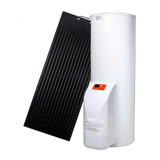
ECO
Thermodynamic Solar
Water Heater
Eco 200esm |Eco 250esm | Eco 300esm
This manual must be used by a qualified installer/service technician. Read all instructions in this manual
before installing. Perform steps in the given order. Failure to comply could result in substantial property
damage, severe personal injury, or death.
NOTICE: ENERGIE reserves the right to make product changes or updates without notice and will not be held
liable for typographical errors in literature.
CONSUMER INFORMATION: PLEASE KEEP ALL INSTRUCTIONS FOR FUTURE REFERENCE
Review: 1
Version: 0
Date: 25/Fev/2015
Installation Instructions and Use & Care Guide
UL
CAN
UL 174
CSA C22.2 No. 110
UL 1995
CSA C22.2 No. 236-11
1
Advertisement
Table of Contents

Subscribe to Our Youtube Channel
Related Manuals for Energie Eco 200esm


Summary of Contents for Energie Eco 200esm
- Page 1 Perform steps in the given order. Failure to comply could result in substantial property damage, severe personal injury, or death. NOTICE: ENERGIE reserves the right to make product changes or updates without notice and will not be held liable for typographical errors in literature.
- Page 2 Installation Instructions and Use & Care Guide Dear Customer, We would like to thank you for choosing an Energie water heater. We dedicate great part of our time developing innovations that promote savings. The thermodynamic solar water heater Eco will surely meet all your expectations and provide many years of comfort with maximum savings.
- Page 3 Installation Instructions and Use & Care Guide The following defined terms are used throughout this manual to bring attention to the presence of hazards of various risk levels, or to important product information. DANGER indicates an imminently hazardous situation which, if not avoided, will result in death or serious injury.
-
Page 4: Table Of Contents
Installation Instructions and Use & Care Guide INDEX GENERAL SAFETY INFORMATION ......................6 1.1. PRECAUTIONS ..........................6 1.2. WATER TEMPERATURE ADJUSTEMENT ..................6 1.3. COMBUSTIBLE MATERIALS ......................7 1.4. MAINTENANCE CONSIDERATIONS....................7 1.5. HYDROGEN GAS ..........................8 1.6. SAFETY CONSIDERATIONS ......................8 1.7. - Page 5 Installation Instructions and Use & Care Guide 9.4. SET-COOLANT COUPLINGS ......................25 9.5. CONNECTION TO THE PANNEL ..................... 26 9.6. CONNECTION OF THERMODYNAMIC GROUP AND STORAGE WATER HEATER ......27 9.7. CONNECTION OF THERMODYNAMIC GROUP AND PANEL ............28 9.8. NITROGEN LOAD .......................... 28 9.9.
-
Page 6: General Safety Information
Installation Instructions and Use & Care Guide 1. GENERAL SAFETY INFORMATION For your safety, the information in this manual must be followed to minimize the risk of fire, explosion, electric shock, and to prevent property damage, personal injury, or death. 1.1. -
Page 7: Combustible Materials
Installation Instructions and Use & Care Guide Figure 1 Safety and energy conservation are factors to be considered when selecting the water temperature setting via the water heater user interface. Water temperatures above 125 °F can cause severe burns or death from scalding. -
Page 8: Hydrogen Gas
Installation Instructions and Use & Care Guide To avoid electric shock, disconnect electrical supply before performing maintenance. To avoid severe burns, allow water heater to cool before performing maintenance. 1.5. HYDROGEN GAS Hydrogen gas can be produced in a hot water system that has not been used for a long period of time (generally two weeks or more). -
Page 9: Package
Installation Instructions and Use & Care Guide Transporting the equipment must be carried out with an inclination below 45º; The equipment must be raised and lowered with extreme care to avoid impact that could damage the material; Make sure the belts and/or transportation straps do not damage the material;... -
Page 10: Required Clearances
Installation Instructions and Use & Care Guide Figure 2: Catch pan detail Note: the auxiliary catch pan must conform to local codes. This water heater SHOULD NOT be installed in a space where liquids which give off flammable vapors are used or stored. -
Page 11: Thermal Expansion
Installation Instructions and Use & Care Guide 4.3. THERMAL EXPANSION Determine if a check valve exists in the inlet water line. It may have been installed in the cold water line as a separate backflow preventer, or may be part of a pressure-reducing valve, water meter, or water softener. A check valve located in the cold water inlet line can cause what is referred to as a “closed water system”. -
Page 12: Tp Relief Valve
Installation Instructions and Use & Care Guide 4.5. TP RELIEF VALVE The pressure rating of the relief valve must not exceed 100 PSI, the maximum working pressure of the water heater as marked on the rating plate. Failure to follow this warning could result in explosion, property damage, personal injury, or death. - Page 13 The use of unauthorized energy-saving devices may shorten the life of the water heater and may endanger life and property. ENERGIE EST, disclaims any responsibility for such loss or injury resulting from the use of such unauthorized devices.
-
Page 14: Running Principle
Installation Instructions and Use & Care Guide 5. RUNNING PRINCIPLE The thermodynamic solar system Eco, is an equipment based upon the principle of cooling by compression – Principle of Carnot – which we designate Thermodynamic Solar Systems: solar panel and heat-pump. The solar panel, the main component, placed outside, is in charge of collecting the energy from: ... -
Page 15: Technical Features
Installation Instructions and Use & Care Guide 6. TECHNICAL FEATURES Unit Dry weight Kg / lb 73 / 160 83 / 182.9 95 / 209.4 Volume Lts / gal 200 / 52,8 250 / 66 300 / 79.25 Type of internal protection Enamelled Cathodic protection Magnesium anode (1”1/4 Female) -
Page 16: Main Components, General Diagram Of Assembly
Installation Instructions and Use & Care Guide 7. MAIN COMPONENTS, GENERAL DIAGRAM OF ASSEMBLY Thermodynamic solar panel L-shaped fastenings for attachment of aluminium panel Set of bolts, female, washer and bushing (6x or 8x) Refrigerant copper pipes Water storage heater Thermodynamic group Hood + Display Bolts CHC M8... -
Page 17: Specifications
Installation Instructions and Use & Care Guide 8. SPECIFICATIONS 8.1. SOLAR PANEL The solar panel is a manufactured in double channel pressed aluminium, with a post-press anodization- oxidation followed by a hydrophobic paiture. There are two types of panels available: left and right panels (according connections side). -
Page 18: Storage Water Heater
Installation Instructions and Use & Care Guide 8.2. STORAGE WATER HEATER The storage water heater is vertical and rests on the floor. The tank is made of carbon steel with enamel coating or made of stainless steel. The thermal insulation is made of expanded polyurethane with a average thickness of 45 mm. -
Page 19: Dimensions Storage Water Heater
Installation Instructions and Use & Care Guide 8.3. DIMENSIONS STORAGE WATER HEATER Version A (mm/ft) B (mm/ft) C (mm/ft) D (mm/ft) E (mm/ft) F (mm/ft) 4.179 74 / 0.242 650 / 2.132 1146 / 3.759 580 / 1.902 1350 / 4.429 1274 / 74 / 0.242 815 / 2.673... - Page 20 Installation Instructions and Use & Care Guide...
-
Page 21: Cooling Fluid
Installation Instructions and Use & Care Guide 8.5. COOLING FLUID The R134a is a HFC coolant, thus not harmful to the ozone layer. It has great chemical and thermal stability, low toxicity, non-inflammable, and is compatible with most materials. The following graphic depicts the behaviour of pressure according to temperature variation. The cooling fluid employed in the whole process is R134a, CFC-free, non-inflammable and without harmful effects for the ozone layer. -
Page 22: Installation
Installation Instructions and Use & Care Guide So the installer must tighten the sockets (C) in the water inlet and outlet (A and B), before attaching the piping (D), as demonstrated in the following sequence: 9. INSTALLATION Assembly sequence: Solar panel ... -
Page 23: Attachment Solar Pannel
Installation Instructions and Use & Care Guide 9.1. ATTACHMENT SOLAR PANNEL The nature of the site and the inclination angle where the panels are installed are important factors to take into account. In order to benefit the most from the sunlight exposure, the panels should have a pitch between 10º... -
Page 24: Set-Up Of The Storage Water Heater
Installation Instructions and Use & Care Guide The panel must be installed facing down, that is, the connections must be turned down. Liquid inlet Vapour outlet (aspiration) 9.2. SET-UP OF THE STORAGE WATER HEATER Keep the equipment sheltered in places susceptible to ice crystals ... -
Page 25: Set-Coolant Couplings
Installation Instructions and Use & Care Guide Detail of the support structure overlapping the bolts c) Allow the structure to rest carefully over the bolts, then tighten them completely. Detail of the support structure overlapping the bolts. 9.4. SET-COOLANT COUPLINGS The cooling fluid couplings must be done by a qualified technician, with a professional certificate of qualifications for this purpose. -
Page 26: Connection To The Pannel
Installation Instructions and Use & Care Guide The piping used must be copper without seams of the refrigeration type (Cu DHP type according to standard ISO1337) DIAMETER OF THE PIPES GAS (aspiration) LIQUID (panel inlet) mm / ft Inches Mm / ft Inches 9,52 / 0.0303 3/8’’... -
Page 27: Connection Of Thermodynamic Group And Storage Water Heater
Installation Instructions and Use & Care Guide Diameter of the Pipe Applied Torque Wrench nº (inches) (Nm) 1/4” 14 to 16 3/8” 33 to 42 9.6. CONNECTION OF THERMODYNAMIC GROUP AND STORAGE WATER HEATER After securing the thermodynamic group to the storage water heater with its bolts, we can proceed with making the refrigeration couplings between the group and the storage water heater. -
Page 28: Connection Of Thermodynamic Group And Panel
Installation Instructions and Use & Care Guide 9.7. CONNECTION OF THERMODYNAMIC GROUP AND PANEL Some of the steps are the repetition of the steps carried out for the connection to the panel. Cut the required measure of the pipe with the edge turned upside down. Sand any remaining rough edges. Shape a conic edge in the pipe and do not forget to place the female coupling on the side of the pipe. -
Page 29: Create Vacuum
Installation Instructions and Use & Care Guide 9.9. CREATE VACUUM During the whole procedure, employ, connections, vacuum pump and pressure gauges suitable for fluid R134a. Employ a vacuum pump only to remove the air and humidity inside the piping. Never use the system coolant to purge the connection pipes. The valves must be completely shut during the vacuum process, in order to create vacuum only in the piping. -
Page 30: Load Of Complementary Cooling Fluid
Installation Instructions and Use & Care Guide 9.10. LOAD OF COMPLEMENTARY COOLING FLUID Your unit has been pre-loaded for connections up to 12 m between the panel and the storage water heater. Longer distances will decrease the performance of your equipment. Before carrying out an additional load of gas into you equipment, you must prepare all the equipment and tools necessary for the operation, such as: ... -
Page 31: Start-Up What To Expect
Installation Instructions and Use & Care Guide 11. START-UP WHAT TO EXPECT NOTE: The following table outlines what can be expected next. Elapsed time Comments 0-3 minutes The compressor is off. This 3 minute off time prevents compressor damage. Compressor turns on and runs for 5 minutes. This 5 minute period ensures the tank 3-8 minutes is full of water Compressor turns off. - Page 32 Installation Instructions and Use & Care Guide 7 – Enter button. For confirm or unlock the key. After change the setpoint temperature through ▲ ▼ keys, consumer need press this key in 10 seconds to confirm; or else, the setpoint temperature can not change. When the panel is locked, we can press this key for 3 seconds to deactivate the lock.
-
Page 33: Display Overview
Installation Instructions and Use & Care Guide 13. DISPLAY OVERVIEW 1. Peak Load Shifting Mode 1 When in this mode, this icon will light. The heat pump mode will run, and users can set water temperature. 2. Peak Load Shifting Mode 2 When in this mode, this icon will light. -
Page 34: Setting The Water Temperature
Installation Instructions and Use & Care Guide When 120°F≥TS≥110°F, lower 2 phases will be illuminated. When 110°F≥TS≥100°F, lowest phase will be illuminated. Note: TS is preset water temperature. 11. Main Screen The display will light once the power supply is connected. During normal usage, this shows water temperature. -
Page 35: About The User Interface Feature Buttons
Installation Instructions and Use & Care Guide Auto Mode combines the energy efficiency of the Economy Mode with the recovery speed and power of Electric Mode. Auto Mode is recommended for normal water usage. To access any of these modes: 1. -
Page 36: Heating Element Replacement
Installation Instructions and Use & Care Guide Diagnostic Function Screen Shot To exit appliance diagnostics, press and hold the ENTER and UP buttons together for one second; otherwise, the appliance will exit automatically after one minute of no activity. 3. Clear Malfunction To clear malfunction, press and hold ENTER and DOWN simultaneously for one second. -
Page 37: Maintenance Procedures
Installation Instructions and Use & Care Guide 8. Make sure the replacement element has the correct voltage and wattage rating by matching it to the rating plate on the water heater. Position the new gasket on the element and insert it into the water heater tank. -
Page 38: Wiring Diagram
Installation Instructions and Use & Care Guide 20. WIRING DIAGRAM... -
Page 39: Maintenance Checklist And Error Codes
Installation Instructions and Use & Care Guide 21. MAINTENANCE CHECKLIST AND ERROR CODES 21.1. TROUBLESHOOTING CHART PROBLEM POSSIBLE CAUSES WHAT TO DO Water dripping down Inlet/Outlet water connections are Tighten the inlet and outlet pipe the outside of the not tightened connections water heater Water usage may have exceeded the... -
Page 40: Error Codes
Installation Instructions and Use & Care Guide 21.2. ERROR CODES The following table describes error codes and possible solutions. If your water heater displays an error code, call a qualified service agent to fix the problem. ERROR DESCRIPTION WHAT TO DO CODE Inspect for proximity to high voltage power sources. - Page 41 Installation Instructions and Use & Care Guide Notes _____________________________________________________________ _____________________________________________________________ _____________________________________________________________ _____________________________________________________________ _____________________________________________________________ _____________________________________________________________ _____________________________________________________________ _____________________________________________________________ _____________________________________________________________ _____________________________________________________________ _____________________________________________________________ _____________________________________________________________ _____________________________________________________________ _____________________________________________________________ _____________________________________________________________ _____________________________________________________________ _____________________________________________________________ _____________________________________________________________ _____________________________________________________________ _____________________________________________________________ _____________________________________________________________ _____________________________________________________________ _____________________________________________________________ _____________________________________________________________ _____________________________________________________________ _____________________________________________________________ _____________________________________________________________ _____________________________________________________________...
- Page 42 Installation Instructions and Use & Care Guide Zona Industrial de Laúndos, Lote 48 Energie est, lda 4570-311 Laúndos – Póvoa de Varzim – Portugal Tel: (+351) 252 600 230 Fax: (+351) 252 600 239 Web: www.energie.pt...
Need help?
Do you have a question about the Eco 200esm and is the answer not in the manual?
Questions and answers