
Related Manuals for REED ST-9800T


Summary of Contents for REED ST-9800T
- Page 1 ST-9800T Model True RMS AC/DC Clamp Meter with Temperature Function Instruction Manual reedinstruments...
-
Page 2: Table Of Contents
Table of Contents Safety..................... 2 Meter.Description................4 Specifications................5-6 Operating.Instructions..............7-9 Battery.Replacement..............9 For.service.on.this.or.any.other.REED.product,.contact.REED.Instruments. at.info@reedinstruments.com. Safety International Safety Symbols This.symbol,.adjacent.to.another.symbol.or.terminal,.indicates. the.user.must.refer.to.the.manual.for.further.information. This.symbol,.adjacent.to.a.terminal,.indicates.that,.. under.normal.use,.hazardous.voltages.may.be.present Double.insulation Safety Notes •. Do.not.exceed.the.maximum.allowable.input.range.of.any.function •. Do.not.apply.voltage.to.meter.when.resistance.function.is.selected. •. Set.the.function.switch.OFF.when.the.meter.is.not.in.use. reedinstruments... - Page 3 Warnings •. Set.function.switch.to.the.appropriate.position.before.measuring. •. When.measuring.volts.do.not.switch.to.current/resistance.modes. •. When.changing.ranges.using.the.selector.switch.always.disconnect.the. test.leads.from.the.circuit.under.test. •. Do.not.exceed.the.maximum.rated.input.limits. Cautions •. Improper.use.of.this.meter.can.cause.damage,.shock,.injury.or.death.. Read.and.understand.this.user.manual.before.operating.the.meter. •. Always.remove.the.test.leads.before.replacing.the.battery. •. Inspect.the.condition.of.the.test.leads.and.the.meter.itself.for.any.damage. before.operating.the.meter..Repair.or.replace.any.damage.before.use. •. Use.great.care.when.making.measurements.if.the.voltages.are.greater.than. 25VAC.rms.or.35VDC..These.voltages.are.considered.a.shock.hazard. •. Remove.the.battery.if.the.meter.is.to.be.stored.for.long.periods. •. Always.discharge.capacitors.and.remove.power.from.the.device.under. test.before.performing.Diode,.Resistance.or.Continuity.tests. • Voltage checks on electrical outlets can be difficult and misleading because.of.the.uncertainty.of.connection.to.the.recessed.electrical. contacts..Other.means.should.be.used.to.ensure.that.the.terminals.are. not.“live”. • If the equipment is used in a manner not specified by the manufacturer, the.protection.provided.by.the.equipment.may.be.impaired. Input Limits Function Maximum Input A.AC,.A.DC 600A V.DC,.V.AC...
-
Page 4: Meter.description
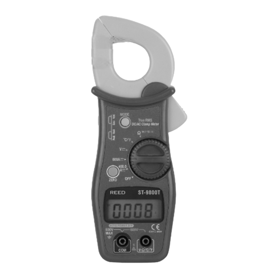
Meter Description Current.clamp Data.Hold.button Peak.Hold.button Mode.select.button ZERO.button LCD.display COM.input.jack Clamp.trigger Rotary.Function.switch 10. V/Ω CAP/TEMP jack Display Description AC.(alternating.current).&.DC.(direct.currrent) Minus.sign 4000.count.(0.to.3999).measurement.reading AutoRange.mode Peak.Hold.mode Diode.test.mode. Audible.Continuity Data.Hold.mode ZERO.(Relative).mode 10.. Low.Battery.icon 11.. Units.of.measure.list reedinstruments... -
Page 5: Specifications
Specifications Function Range & Resolution Accuracy (% of reading) DC Current 400.0.ADC 0.to.70A:.±.(2.5%.+.0.6A) 70.to.300A:.±.(3.0%.+.0.3A) 300.to.400A:.±.(3.5%.+.0.3A) 600.ADC 0.to.150A:.±.(2.5%.+.4A) 151.to.350A:.±.(3.0%.+.4A) 351.to.600A:.±.(4.0%.+.6A) AC Current 400.0.AAC 0.to.70A:.±.(3.0%.+.0.6A) 70.to.300A:.±.(3.5%.+.0.3A) 300.to.400A:.±.(3.5%.+.0.6A) 600.AAC 0.to.150A:.±.(3.0%.+.4A) 151.to.350A:.±.(3.5%.+.5A) 351.to.600A:.±.(4.0%.+.8A) DC Voltage 400.0.mVDC ±.(0.5%.+.5.digits) 4.000.VDC 40.00.VDC ±.(1.2%.+.3.digits) 400.0.VDC 600.VDC ±.(1.5%.+.3.digits) AC Voltage 4.000.VAC ±.(1.0%.+.5.digits) 40.00.VAC... - Page 6 Capacitance 40.00.nF ±.(5.0%.+.7.digits) 400.0.nF 4.000.uF ±.(3.5%.+.5.digits) 40.00.uF 100.0.uF ±.(5.0%.+.5.digits) Clamp size. Opening.1.3”.(33mm).approx Diode Test. Test..current.of.0.3mA.typical;.. Open.circuit.voltage.1.5V.DC.typical. Continuity Check Threshold <50Ω; Test current < 1mA Low Battery Indication. “BAT”.is.displayed Overrange Indication. “OL..“.is.displayed Measurements Rate. 2.per.second,.nominal Temperature sensor. Type.K.thermocouple Input Impedance 7.8MΩ (VDC and VAC) Display. 3-3/4.digits.(4000.counts).LCD AC bandwidth . 50/60Hz.(AAC.and.VAC) AC response.
-
Page 7: Operating.instructions
Operating Instructions NOTE:.Read.and.understand.all.warning.and.precaution.statements. listed.in.the.safety.section.of.this.operation.manual.prior.to.using.this. meter..Set.the.function.select.switch.to.the.OFF.position.when.the. meter.is.not.in.use. AC/DC Current Measurements WARNING:.Ensure.that.the.test.leads.are.disconnected.from.the.meter. before.making.current.clamp.measurements. 1..Set.the.Function.switch.to.the.. 600 or 400A.range..If.the.range.of.the.. measured.is.not.known,.select.the. higher range first then move to the lower.range.if.necessary. 2..Select.AC.or.DC.with.the.AC/DC.. button..Press.the.zero.button.to.zero. the.meter.in.the.DCA.mode.only. 3..Press.the.trigger.to.open.jaw..Fully.en- close.one.conductor.to.be.measured. 4..The.clamp.meter.LCD.will.display.the. reading. AC/DC Voltage Measurements 1..Insert.the.black.test.lead.into.the.. negative.COM.terminal.and.the.red.test.lead.. into.the.positive.V.terminal. 2..Set.the.function.switch.to.the.V.position. 3..Select.AC.or.DC.with.the.AC/DC.button.. 4..Connect.the.test.leads.in.parallel.. to.the.circuit.under.test. 5..Read.the.voltage.measurement.. on.the.LCD.display. reedinstruments... -
Page 8: Capacitance Measurements
Resistance and Continuity Measurements 1..Insert.the.black.test.lead.into.the.negative.COM.terminal.and.the.red. test.lead.into.the.positive.terminal. Ω 2..Set.the.function.switch.to.the. CAP.position. 3..Use.the.multifunction.button.to.select.resistance. 4..Touch.the.test.probe.tips.across.the.circuit.or.component.under.test..It. is.best.to.disconnect.one.side.of.the.device.under.test.so.the.rest.of.the. circuit.will.not.interfere.with.the.resistance.reading. 5..For.Resistance.tests,.read.the.resistance.on.the.LCD.display. 6. For Continuity tests, if the resistance is < 50Ω, a tone will sound. Capacitance Measurements WARNING:.To.avoid.electric.shock,.discharge.the.capacitor.under.test. before.measuring. 1..Set.the.function.switch.to.. Ω CAP.Position. the. 2..Press.the.multifunction.button.to.select.the. capacitance.function. 3..Insert.the.black.test.lead.banana.plug.into. the.negative.(COM).jack.and.the.red.test. lead.banana.plug.into.the.positive.jack. 4..Touch.the.test.probe.tips.across.the.part. under.test. 5..Read.the.capacitance.in.the.display. 6..The.display.will.indicate.the.proper.decimal. point.and.value. reedinstruments... -
Page 9: Temperature Measurements
Temperature Measurements WARNING:.To.avoid.electric.shock,.disconnect.both.test.probes.from. any.source.of.voltage.before.making.a.temperature.measurement. 1..Set.the.function.switch.to.TEMP. 2..Insert.the.Temperature.Probe.into.the.negative.(COM).and.the.positive. jacks,.making.sure.to.observe.the.correct.polarity. 3..Touch.the.Temperature.Probe.head.to.the.part.whose.temperature.you. wish.to.measure..Keep.the.probe.touching.the.part.under.test.until.the. reading.stabilizes.(about.30.seconds). 4..Read.the.temperature.in.the.display..The.digital.reading.will.indicate.the. proper.decimal.point.and.value. WARNING:.To.avoid.electric.shock,.be.sure.the.thermocouple.has.been. removed.before.changing.to.another.measurement.function Data Hold To.freeze.the.LCD.meter.reading,.press.the.data.hold.button..The.data. hold.button.is.located.on.the.left.side.of.the.meter.(top.button)..While.data. hold.is.active,.the.DH.display.icon.appears.on.the.LCD..Press.the.data. hold.button.again.to.return.to.normal.operation. Peak Hold To.hold.the.highest.reading.on.the.LCD,.press.the.peak.hold.button..The. peak.hold.button.is.located.on.the.left.side.of.the.meter.(bottom.button).. The.meter.reading.will.not.change.as.readings.change,.rather.it.will.only. display.the.highest.reading.encountered.since.the.peak.hold.button.was. pressed..Press.the.peak.hold.button.again.to.return.to.normal.operation. Battery Replacement 1..Remove.the.three.rear.Phillips.head.screws 2..Open.the.battery.compartment 3..Replace.the.‘9V’.battery..IEC.6F22,.NEDA.1604. 4..Re-assemble.the.meter reedinstruments... - Page 10 Notes _________________________________________ ________________________________________________ ________________________________________________ ________________________________________________ ________________________________________________ ________________________________________________ ________________________________________________ ________________________________________________ ________________________________________________ ________________________________________________ ________________________________________________ ________________________________________________ ________________________________________________ ________________________________________________ ________________________________________________ ________________________________________________ ________________________________________________ ________________________________________________ reedinstruments...
Need help?
Do you have a question about the ST-9800T and is the answer not in the manual?
Questions and answers