Table of Contents
Advertisement
Quick Links
Advertisement
Table of Contents

Related Manuals for REED ST-332


Summary of Contents for REED ST-332
- Page 1 ST-332 Model 400A AC/DC Clamp Meter Instruction Manual reedinstruments...
-
Page 2: Table Of Contents
Table Of Contents Safety..................3-4 Meter.Description................5 Specifications................6-7 Operating.Instructions...............8-11 AC/DC Current Measurements ........... 8 DC/AC Voltage Measurements ............ 8 Resistance & Continuity Measurements ........9 Diode Measurements ..............9 Capacitence Measurements ............9 Frequency or % duty cycle measurements ........ 10 Data Hold ................. -
Page 3: Safety
Safety International Safety Symbols This.symbol,.adjacent.to.another.symbol.or.terminal,.indicates. the.user.must.refer.to.the.manual.for.further.information. This.symbol,.adjacent.to.a.terminal,.indicates.that,.under.normal. use,.hazardous.voltages.may.be.present Double.insulation Safety Notes •. Do.not.exceed.the.maximum.allowable.input.range.of.any.function •. Do.not.apply.voltage.to.meter.when.resistance.function.is.selected. •. Set.the.function.switch.OFF.when.the.meter.is.not.in.use. Warnings •. Set.function.switch.to.the.appropriate.position.before.measuring. •. When.measuring.volts.do.not.switch.to.current/resistance.modes. •. Do.not.measure.current.on.a.circuit.whose.voltage.exceeds.240V. •. When.changing.ranges.using.the.selector.switch,.always.disconnect.the. test.leads.from.the.circuit.under.test. •. Do.not.exceed.the.maximum.rated.input.limits. Cautions Improper.use.of.this.meter.can.cause.damage,.shock,.injury.or.death.. Read.and.understand.this.user.manual.before.operating.the.meter.. •. Always.remove.the.test.leads.before.replacing.the.battery..Inspect.the. condition.of.the.test.leads.and.the.meter.itself.for.any.damage.before. operating.the.meter.. reedinstruments... - Page 4 Cautions con’t •. Repair.or.replace.any.damage.before.use. •. Use.great.care.when.taking.measurements.when.the.voltages.are. greater.than.25VAC.rms.or.35VDC..These.voltages.are.considered.a. shock.hazard. •. Remove.the.battery.if.the.meter.is.to.be.stored.for.long.periods. •. Always.discharge.capacitors.and.remove.power.from.the.device.under. test.before.performing.Diode,.Resistance.or.Continuity.tests. • Voltage checks on electrical outlets can be difficult and misleading because.of.the.uncertainty.of.connection.to.the.recessed.electrical. contacts..Other.means.should.be.used.to.ensure.that.the.terminals.are. not.“live”. • If the equipment is used in a manner not specified by the manufacturer, the.protection.provided.by.the.equipment.may.be.impaired. Input Limits Function Maximum.Input A.AC,A.DC 400A V.DC,.V.AC,.Frequency,.Duty.Cycle 600V.DC/AC Resistance,.Diode,.Continuity,.Capacitance.Test 250V.DC/AC reedinstruments...
-
Page 5: Meter.description
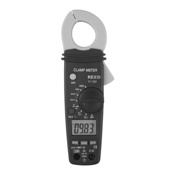
Meter Description 1-. Current.Clamp 2-. Clamp.Trigger 3-. Rotary.Function.Switch 4-. LCD.Display 5-. ZERO.Button 6-. Data.Hold.and.Backlight.Button 7-. Mode.Select.Button 8-. Range.Delect.Button 9-. Hz/%.Duty.Button 10-. COM.Input.Jack. 11- V Ω °C/°F Jack 12-. Battery.Cover. Display Descriptions Direct.Currrent AC .. Alternating.Current Minus.Sign 4000.Count.. (0.to.3999).. Measurement.Reading AUTO. AutoRange.Mode ZERO. ZERO.Mode Diode.Test.Mode. -
Page 6: Specifications
Specifications Function Range & Resolution Accuracy (% of reading) 0~20.00ADC ±.(2.5%.+.6.digits) 40.00.ADC 20.00~40.00ADC ±.(3%.+.6.digits) DC.Current 0~300.0ADC ±.(2.5%.+.6.digits) 400.0.ADC 300.0~400.0ADC ±.(3.5%.+.6.digits) 0~20.00AAC ±.(3%.+.10.digits) 40.00.AAC 20.00~40.00AAC ±.(5%.+.10.digits) AC.Current 0~300.0AAC ±.(3%.+.10.digits) 400.0.AAC 300.0~400.0AAC ±.(5%.+.10.digits) 4.000.VDC ±.(0.8%.+.3.digits) 40.00.VDC DC.Voltage ±.(1.5%.+.3.digits) 400.0.VDC ±.(2.0%.+.3.digits) 600.VDC 400.0.mVAC ±.(1.0%.+.10.digits) 4.000.VAC AC.Voltage... - Page 7 Specifications con’t Clamp.Size. Opening.0.9”.(23mm).approx Diode.Test. Test.current.of.0.3mA.typical;.. Open.circuit.voltage.1.5V.DC.typical. Continuity Check Threshold <150Ω; Test current < 1mA Low.Battery.Indication. “. . ”.is.displayed Overrange.Indication. “OL”.is.displayed Measurements.Rate. 2.per.second,.nominal Input Impedance 7.8MΩ (VDC and VAC) Display. 4000.counts.LCD AC.Current. 50/60Hz.(AAC) AC.Voltage.Bandwidth.. 50/400Hz.(VAC) Operating Temperature 14 to 122°F (-10 to 50°C) Storage Temperature -14 to 140°F (-30 to 60°C) Relative Humidity 90% (0°C to 30°C); 75% (30°C to 40°C);. 45% (40°C to 50°C) Altitude. Operating:.3000m;.Storage.10,000m Over.Voltage. Category.III.600V Battery. Two.1.5V.“AAA”.Batteries Auto.OFF. approx..30.minutes. Dimensions/Weight.
-
Page 8: Operating.instructions
Operation NOTICE: Read. and. understand. all. warning. and. precaution. state- ments. listed. in. the. safety. section. of. this. operation. manual. prior. . to.using.this.meter..Set.the.function.select.switch.to.the.OFF.position. when.the.meter.is.not.in.use. AC/DC Current Measurements WARNING: Ensure.that.the.test.leads.are.disconnected.from.the.meter. before.making.current.clamp.measurements. 1..Set.the.Function.switch.to.the.400ADC, 40ADC, 400AAC or 40AAC range..If.the.range.of.the.measured.is.not.known,.select.the.higher. range first then move to the lower range if necessary. 2..Press.the.trigger.to.open.jaw..Fully.enclose.one.conductor.to.be.measured. 3..The.clamp.meter.LCD.will.display.the.reading. DC/AC Voltage Measurements 1..Insert.the.black.test.lead.into.the.negative.COM.terminal.and.the.red. -
Page 9: Resistance & Continuity Measurements
Resistance and Continuity Measurements 1..Insert.the.black.test.lead.into.the.negative.COM.terminal.and.the.red. test.lead.into.the.positive.terminal. Ω 2..Set.the.function.switch.to.the . .position. 3..Use.the.multifunction.MODE.button.to.select.resistance. 4..Touch.the.test.probe.tips.across.the.circuit.or.component.under.test... It.is.best.to.disconnect.one.side.of.the.device.under.test.so.the.rest.of. the.circuit.will.not.interfere.with.the.resistance.reading. 5..For.Resistance.tests,.read.the.resistance.on.the.LCD.display. 6. For Continuity tests, if the resistance is < 150Ω, a tone will sound. Diode Measurements 1..Insert.the.black.test.lead.banana.plug.into.the.negative.COM.jack.and. the.red.test.lead.banana.plug.into.the.positive.diode.jack. 2..Turn.the.rotary.switch.to.the . . position. 3..Press.the.MODE.button.until.“. . ”.appears.in.the.display. 4..Touch.the.test.probes.to.the.diode.under.test..Forward.voltage.will.. indicate.0.4V.to.0.7V..Reverse.voltage.will.indicate.“OL”..Shorted.. devices.will.indicate.near.0mV.and.an.open.device.will.indicate.“OL”.. in.both.polarities. Capacitance Measurements WARNING:. To. avoid. electric. shock,. disconnect. power. to. the. unit. . under.test.and.discharge.all.capacitors.before.taking.any.capacitance. -
Page 10: Frequency Or % Duty Cycle Measurements
Frequency or % duty cycle measurements 1..Set.the.rotary.function.switch.to.the.“VDC/AC,Hz/%”.position. 2..Insert.the.black.lead.banana.plug.into.the.negative.COM.jack.and.the. red.test.lead.banana.plug.into.the.positive.V.jack. 3..Select.Hz.or.%.duty.with.the.Hz/%.button. 4..Touch.the.test.probe.tips.to.the.circuit.under.test. 5..Read.the.frequency.on.the.display. Data Hold To.freeze.the.LCD.meter.reading,.press.the.data.hold.button..The.data. hold.button.is.located.on.the.left.side.of.the.meter.(top.button)..While.data. hold.is.active,.the.HOLD.display.icon.appears.on.the.LCD..Press.the.data. hold.button.again.to.return.to.normal.operation. Note:.The.HOLD.feature.will.activate.when.the.Backlight.is.turned.on.. Press.the.HOLD.key.again.to.exit.Hold. Backlight Press.and.hold.the.HOLD.the. .key.for.>1.second.to.turn.on.or.off.the. display.backlight.function.. Note:.The.HOLD.feature.will.activate.when.the.Backlight.is.turned.on.. Press.the.HOLD.key.again.to.exit.Hold. Zero Button For.DCA.and.Capacitance.Zero.&.Offset.adjustment. reedinstruments... -
Page 11: Manual Ranging
Manual Ranging The.meter.turns.on.in.the.autoranging.mode..Press.the.Range.button.to. go.to.manual.ranging..Each.press.of.the.range.button.will.step.to.the.next. range.as.indicated.by.the.units.and.decimal.point.location..Press.and. hold.the.Range.button.for.two.seconds.to.return.to.autoranging..Manual. ranging.does.not.function.in.the.AC.Current,.Diode.and.Continuity.check. functions. Battery Replacement 1..Remove.the.one.rear.Phillips.head.screw 2..Open.the.battery.compartment 3..Replace.the.required.two.“AAA”.batteries.(UM4.R03). 4..Re-assemble.the.meter For.service.on.this.or.any.other.REED.product,.contact.REED.Instruments. at.info@reedinstruments.com. reedinstruments... - Page 12 Notes _________________________________________ ________________________________________________ ________________________________________________ ________________________________________________ ________________________________________________ ________________________________________________ ________________________________________________ ________________________________________________ ________________________________________________ ________________________________________________ ________________________________________________ ________________________________________________ ________________________________________________ ________________________________________________ ________________________________________________ ________________________________________________ ________________________________________________ ________________________________________________ reedinstruments...
Need help?
Do you have a question about the ST-332 and is the answer not in the manual?
Questions and answers