
Related Manuals for REED ST-3347


Summary of Contents for REED ST-3347
- Page 1 ST-3347 Model AC/DC True RMS Clamp Meter Instruction Manual reedinstruments...
-
Page 2: Table Of Contents
Table of Contents Measuring Limits .................2 Safety Information ................3-5 Features ....................5 Meter Description ................6 Specifications .................. 6-7 DC Current Measurement ..............8 AC TRMS Current Measurement ............9 DC Voltage Measurement ..............10 AC TRMS Voltage Measurement ............11 Resistance Measurement ..............12 Capacitance Measurement ...............13 Frequency Measurement ..............14 Temperature Measurement ...............15 Diode Test ..................16... -
Page 3: Safety Information
Safety Information This manual contains information that must be followed to operate the meter safely and maintain the meters safe operating condition. If the meter is not used in a manner specified in this manual, the protection provided by the meter may be impaired. The model has been designed and complies With IEC 61010-1 and EN 61010-1 Safety Requirements for Electronic Measuring Apparatus. - Page 4 • Do not turn the function switch while test leads are connected to the meter. • Do not install substitute parts or make modifications to the meter. Return the meter to your distributor for repair or re-calibration. For service on this or any other REED product, contact REED Instruments at info@reedinstruments.com. • Ensure the meter is switched off before opening the battery cover when replacing the battery.
-
Page 5: Features
• Do not use abrasives or solvents on the meter. To clean it use a damp cloth and mild detergent only. Only qualified and trained service techni- cians should perform calibration and repair of the meter. For service on this or any other REED product, contact REED Instruments at info@reedinstruments.com. Features • True RMS measurement of AC Current and AC Voltage •... -
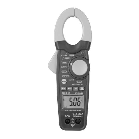
Page 6: Meter Description
Meter Description Transformer Jaws Jaw Trigger Function Switch Data Hold Button DC Amps Zero Adjustment Mode Button Backlight Button Peak Hold Button for Volts and Current Display Volt, Resistance, Frequency, COM Terminal Capacitance, Temperature, Terminal Specifications Clamp Size 30mm Opening Approx Diode Test Test Current of 0.3mA typical;... - Page 7 Range Measuring Range Resolution Accuracy (% of Reading) DC CURRENT 0 ~ 40.00A 0.01A ± (2.8% + 10 digits) 400A 0 ~ 400.0A 0.1A ± (2.8% + 8 digits) 1000A 0 ~ 1000A ± (3.0% + 8 digits) AC CURRENT 0 ~ 40.00A 0.01A ± (2.8% + 10 digits) 400A 0 ~ 400.0A 0.1A ± (2.8% + 8 digits) 1000A 0 ~ 1000A ± (3.0% + 8 digits) DC VOLTAGE...
-
Page 8: Dc Current Measurement
DC Current Measurement Warning Ensure that the test leads are disconnected from the meter before making current measurements. 1. Set the Function switch to 1000A or 400A or 40A range position, and make sure that the current under test does not exceed the upper limit of the measuring range you have selected. -
Page 9: Ac Trms Current Measurement
AC True RMS Current Measurement Warning Ensure that the test leads are disconnected from the meter before making current measurements. 1. Set the function switch to 1000A~ or 400A~ or 40A~ range position, and make sure that the current under test does not exceed the upper limit of the measuring range you have selected 2. -
Page 10: Dc Voltage Measurement
DC Voltage Measurement 1. Set the Function switch to range position. The meter automatically defaults to DC Volts. 2. Insert the red test lead into the “V Ω TEMP HZ” input terminal and the black lead to the “COM” terminal. 3. -
Page 11: Ac Trms Voltage Measurement
AC True RMS Voltage Measurement 1. Set the function switch to range position. 2. Press the MODE button to select the AC Volt range. The meter automatically defaults to DC Volts. 3. Insert the red test lead into the “V Ω TEMP HZ” input terminal and the black lead to the “COM”... -
Page 12: Resistance Measurement
Resistance Measurement 1. Set the function switch to range position. The meter auto- matically defaults to resistance range. 2. Insert the red test lead into the “V Ω TEMP HZ” input terminal and the black lead to the “COM” terminal. 3. -
Page 13: Capacitance Measurement
Capacitance Measurement 1. Set the function switch to range position. 2. Insert the red test lead into the “V Ω TEMP HZ” input terminal and the black lead to the “COM” terminal. 3. Connect the other end of the test leads to the circuit or component under test. -
Page 14: Frequency Measurement
Frequency Measurement 1. Set the function switch to range position. The meter automatically defaults to Frequency range. 2. Press the MODE button for 3 seconds to select the Frequency range. The meter automatically defaults to DC Volts. 3. Insert the red test lead into the “V Ω TEMP HZ” input terminal and the black lead to the “COM”... -
Page 15: Temperature Measurement
Temperature Measurement 1. Set the function switch to TEMp range position. The meter automatically defaults to °C range. 2. Insert the meter white temperature adaptor into the “V Ω TEMP HZ” input terminal and the “COM” terminal. Ensure that the “-” marking on the adaptor is inserted into the “COM”... -
Page 16: Diode Test
Diode Test 1. Set the function switch to range position. 2. Press the MODE button to select the Diode Test range. The meter automatically defaults to Resistance. 3. Insert the red test lead into the “V Ω TEMP HZ” input terminal and the black lead to the “COM”... -
Page 17: Continuity Testing
Continuity Testing 1. Set the function switch to range position. 2. Press the MODE button to select the Continuity Test range. The meter automatically defaults to Resistance. 3. Insert the red test lead into the “V Ω TEMP HZ” input terminal and the black lead to the “COM”... -
Page 18: Data Hold Functions
The backlight is ideally used in dark or dimly lit areas. 1. Press the button for 3 seconds, and the bright white light will come on. 2. To turn off the backlight press the button for 3 seconds. Note: The use of the backlight will reduce the battery life considerably. For service on this or any other REED product, contact REED Instruments at info@reedinstruments.com. reedinstruments... -
Page 19: Auto Power Off
Auto power Off This feature automatically turns off the meter after approximately 20 minutes from the last measurement taken. To turn the meter back on, press any button or move the rotary switch to any position. Ensure the test leads are disconnected from any circuit to avoid injury or damage to the meter. Battery Replacement When the sign appears on the LCD, this indicates the battery... - Page 20 Notes _________________________________________ ________________________________________________ ________________________________________________ ________________________________________________ ________________________________________________ ________________________________________________ ________________________________________________ ________________________________________________ ________________________________________________ ________________________________________________ ________________________________________________ ________________________________________________ ________________________________________________ ________________________________________________ ________________________________________________ ________________________________________________ ________________________________________________ ________________________________________________ reedinstruments...
Need help?
Do you have a question about the ST-3347 and is the answer not in the manual?
Questions and answers