
Related Manuals for GE Logix 764


Summary of Contents for GE Logix 764
- Page 1 Logix 764 Operation Manual Models: 293/298 Magnum IT Twin Alternating Twin Parallel Single with Remote Regeneration Start Multi-Single Tank with Lockout...
-
Page 3: Table Of Contents
Outdoor Locations ............7 Assembling the Logix 764 Control to the Magnum Valve . - Page 4 Remote Regeneration Start ......... 39 Connecting the Logix 764 Multi Single Tank Control ....40 Troubleshooting .
-
Page 5: Safety Information
Safety Information This water conditioner’s control valve conforms to UL/CE • Do not allow this water conditioning system to freeze. Standards. Generic valves were tested and certified for Damage from freezing will void this water compliance as verified by the agency listing. conditioning system’s warranty. -
Page 6: Installation Profile Summary
Installation Profile Summary Installation Date: _______________________________ Electronic Demand Settings Installation Location: ____________________________ Time of day ________________ Installer(s): _____________________________________ Day of week ________________ Phone Number:_________________________________ Time of regeneration ________________ Valve Number: _________________________________ Number of days between regeneration (99 day calendar override) ________________ Application Type: (Softener) (Filter) (Dealkalizer) Amount of regenerant used per regeneration or filter... -
Page 7: How To Use This Manual
Note: Helpful hint to simplify procedure. • Knowledge of water conditioning and how to determine proper control settings. The Logix 764 control can be installed on several type valves that can have twin alternating, twin parallel or • Adequate plumbing skills. -
Page 8: Location Selection
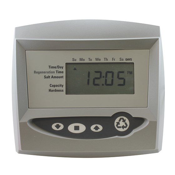
LCD Display SU MO TU WE TH FR SA Time & Day Regen Time & Day Front Salt Capacity x100 Hardness Lbs/ft³ Down Button Manual Regen Button No-Salt Detector (Chlorine Generator) Up Button Set Button Connection (not used AC Adapter on Magnum Valves) (low voltage) Multi Single Tank... -
Page 9: Outdoor Locations
Outdoor Locations When the water conditioning system is installed outdoors, temperatures will affect the control. The display may several items must be considered. become unreadable but the control should continue to function. When the temperature returns to normal • Moisture – The valve and control are rated for NEMA 3 operating limits the display will re-appear. -
Page 10: Assembling The Logix 764 Control To The Magnum Valve
Assembling the Logix 764 Control to the Slide Camshaft Magnum Valve Slide the camshaft toward the back of the valve by pressing on the release tab and pulling on the back end of The control and the Magnum valve work together as an the camshaft (Figure 8). - Page 11 Inlet, Outlet and Drain Connections Normal Standoffs The inlet, outlet, and drain connections are designed to accept a GE Water Technologies supplied CPVC or brass adapter (Figure 11). The adapters provide a convenient union for the three connection ports on the valve. In addition, they incorporate a positive O-ring face seal for ease of installation and leak free operation.
- Page 12 Hydraulic Output Signal Magnum Tank Adapter An optional hydraulic output signal is available on the The tank adapter on the control valve is designed to be valve. An optional cam lobe on pilot valve #6 is used on the compatible with a 4 inch-8UN (8 threads per inch) tank camshaft assembly to initiate the hydraulic output signal opening.
- Page 13 additional electrical or switch closure signals during the regeneration or backwash cycles. Coupled with the optional breakaway cams, signals can be sent to external system equipment at virtually any time while the control/ camshaft motor is running. Consult the instruction sheet covering the multi-switch option for additional application and programming information.
-
Page 14: Magnum General Specifications
Dimensions ..............................26-11/16" L, 16-1/4" W, 10-11/16" H Approximate Weight (Valve and Control) ..........................23.3 lbs. (10.6 kg.) Electrical* Voltage - Logix 764 Series Control..................... 12 VAC wall mount transformer only Power Consumption.......................................4 watts *See section on Electronic Controls for alternative electrical configurations. -
Page 15: General Installation Information
Flow controls from 5 to 40 gpm (18.92 to 151.4 Lpm) apply back pressure to the pilot drain at any time. are available from GE Water Technologies and can be Crimping the pilot drain line or installing the line to go up, easily installed in the drain line. -
Page 16: Magnum Valve Installation Guide (Top Mount)
Electrical 1. Electrical requirements for the installation depends on the configuration of the control. 2. The standard North American Series Logix electronic control is supplied with a 12 volt AC adapter. Optional AC adapters must be ordered separately for all Auxiliary Hydraulic international 12 VAC configurations. -
Page 17: Magnum It Dimensional Specifications
Magnum IT Dimensional Specifications 2-Inch Inlet and Outlet, 1 1/2-Inch Drain 13-1/2 (34.2 cm) (22.9 cm) 7-1/2 (19 cm) 2-15/16 (7.5 cm) 1-11/16 (4.3 cm) 6-1/2 (17.8 cm) (16.5 cm) 9-3/4 (24.8 cm) 16-1/4 (41.3 cm) 4-1/2 4-1/2 (11.4 cm) (11.4 cm) 4-7/16 (11.3 cm) -
Page 18: Typical Installation Drawings
Typical Installation Drawings Twin Tank Multiple Tank Figure 19... -
Page 19: Camshaft Cycle Positions
Camshaft Cycle Positions 764 Control Operation The front end of the camshaft has an indicator cup. The Power Loss Memory Retention cup has slots in the outer edge and cycle numbers on the The 764 control features battery-free Time of Day and Day inside face. -
Page 20: Flow Diagrams
Flow Diagrams The Magnum control valve utilizes a series of pilot valves to 3-cycle filter configuration. Both the Hardwater Bypass properly position the diaphragm valve cartridges (Figure and No Hardwater Bypass service flow diagrams are 21). The pilot valves are activated by the camshaft (Figure presented. - Page 21 Figure 23...
- Page 22 Figure 24...
- Page 23 Figure 25...
- Page 24 Figure 26...
-
Page 25: Identifying The Logix Control
On the back of the control valve is a silver label that shows your model number and version revision. Model number: 764 GE Infrastructure GE Infrastructure Milwaukee, WI USA Milwaukee, WI USA... -
Page 26: Display Icons & Cursors
Display Icons & Cursors WE TH FR SA DAYS SU MO TU Time/Day Regeneration Time Salt Amount If your Logix 764 controller was purchased as a filter control, the overlay will show: Time/Day, Capacity x100 Backwash Time, Backwash Length Hardness and Capacity. -
Page 27: Keypad - Buttons
Programming Conventions 23. Parameter (P). Displayed only in Level II Programming. The number displayed by #23 identifies which The 700 series controller is programmed using the parameter is currently displayed. buttons on the keypad. The programming instructions are described two ways whenever a section has keypad 24. -
Page 28: Placing Water Conditioning System Into Operation
When water flows steady from the faucet, the tank(s) are purged. Note: All Logix 764 controls will be shipped in the service (treated water) position. Check to see that the camshaft 4. Turn off the faucet then turn off the incoming water is aligned to service position. - Page 29 For a 293/298A system: the control will automatically Table 2 syncronize the cam positions. Resin Volume - 1.0 ft and 25 Liter Steps Tank 1 will move to standby Tank 2 will move to service Resin Volume err# will be displayed when the Tank 1 cam is Tank Dia moving.
-
Page 30: Level L Programming - 764 Control With 298 Valve, 5 Cycle Conditioner
Level l Programming - 764 Control with 298 Valve, 5 Cycle Conditioner Screen Buttons to Description Range Press SU MO TU WE TH FR SA DAYS Time/Day Regeneration Time Cubic feet: 3.00 then Resin Volume Salt Amount Select correct resin volume press Capacity 20.00... -
Page 31: Level L Programming - 764 Control With 293 Valve, 3 Cycle Filter
Level l Programming - 764 Control with 293 Valve, 3 Cycle Filter Screen Buttons to Description Range Press SU MO TU WE TH FR SA DAYS Time/Day Backwash Time then Program Type Backwash Length Select "F" press Capacity SU MO TU WE TH FR SA DAYS Time/Day press... -
Page 32: Placing Water Conditioning System Into Operation (Continued)
Note: 293/298 Alternating and parallel tank systems the tank, add water until the water level is have one Logix 764 control that is mounted on tank 1. approximately 1 inch (25 mm) above the Tank 2 has a blank faceplate and the valve is controlled platform. - Page 33 8. If the water level is receding from the regenerant tank you can quick cycle the control to the C8 Regenerant tank refill position. A. The control will cycle to the regenerant tank refill cycle, and water will be directed down through the regenerant line to the regenerant tank.
-
Page 34: In Service Display
Note: When the control is set up for a twelve-hour clock Note: The faucet icon is displayed on all the Logix 764 a PM indicator will illuminate when the displayed time is in controls when there is flow. -
Page 35: Level Ii Programming - P Values
Level II Programming – P Values ll parameters will not need to be adjusted as the default settings accommodate most applications. Contact your Level II program parameters can be adjusted to fine-tune Water Treatment Professional before attempting any the conditioner’s operation. The parameters are programming. -
Page 36: Programming The Lockout Feature
Programming the Lockout Feature All Level I parameters can be locked out when the control is in Level ll programming. Simply press the REGEN button during Level ll programming and a Lock Icon will appear indicating that the specific setting has been locked out. When locked out, the setting cannot be adjusted. -
Page 37: Level Lll Cycle Programming - C Values
Level lll Cycle Programming – C Values accessible by pressing and holding the UP and SET buttons until the display shows a “C” value. Several Level III program parameters can be adjusted to fine-tune a conditioners operation for non-standard Note: The control must by in the treated water position applications. -
Page 38: Level Iv Viewing History - H Values
Level IV Viewing History - H Values Historical information can be viewed by pressing the SET and DOWN buttons simultaneously, with the 764 control in the home position. Release both buttons when the control displays an “H” value. Press the UP or DOWN buttons to navigate to each setting. -
Page 39: Manual Regeneration Options
Manual Regeneration Options Note: The tank in service (on-line) cannot be regenerated while the other tanks are isolated. Water for backwash would not be available. The 764 control features several options that offer additional flexibility for manually regenerating the conditioner. On alternating systems the tank in standby will move through regeneration to service. -
Page 40: Regeneration Modes For Parallel Systems
Regeneration Modes for Parallel Systems Table 5 P16 = 0 Parameter P16 is used to determine the method for demand initiated regeneration. Four regeneration modes Flow Continuous are possible. Priority Efficiency Rate Soft Water • P16 = 0, Delayed Regeneration with a Smart Reserve •... -
Page 41: Wiring Diagrams
Wiring Diagrams Connecting the Logix 764 Twin Alternating or Parallel Controls The twin sensor and extension cables are used for twin unit parallel and alternating applications. Four standard connections are required for operation; the power AC adapter, the flow sensor, motor/optical sensor, and the connection between tank 1 and tank 2 controls. -
Page 42: Connecting The Logix 764 Multi Single Tank Control
Connecting the Logix 764 Multi Single Tank Control Logix 764 control on Tank 1 Repeat for all remaining tanks Logix 764 control Logix 764 control on Tank 2 on Tank 3 Note: Cable PN 3019464 sold separately. Figure 33... -
Page 43: Troubleshooting
Troubleshooting 764 Controller – Error Codes & 298 ”L” with Check Salt Light Problem Possible Cause Solution ERR 1 is displayed. Program settings have been corrupted. Press any key and reprogram Level I settings. ERR 3 is displayed. Controller on tank 1 does not know the Wait for two minutes for the controller to position of the camshaft. -
Page 44: System Troubleshooting
ERR 4 is displayed. If single tank system.. Verify system setting is programmed to 293/298“L”. Controller on tank 2 does not know the Wait for two minutes for the controller to position of the camshaft. Camshaft return to Home position. The hourglass should be rotating to find Home position. - Page 45 Improper regeneration. Repeat regeneration after making certain correct regenerant dosage was set. Hard water leakage after Leaking of external bypass valve. Replace bypass valve. (Contact dealer). regeneration. O-Ring around riser pipe damaged. Replace O-ring System capacity too low due to Reset control and program resin volume incorrect resin volume setting to correct setting...
-
Page 46: Magnum Valve Cartridge Troubleshooting
Magnum Valve Cartridge Troubleshooting This procedure provides sequential troubleshooting steps Table 10 Magnum Valve Leak to Main Drain to isolate a suspect cartridge. Figure 34 displays the Troubleshooting locations of all cartridges. Regenerate the unit if the media bed is exhausted, then NOTE: The Dynamic Pressure applied to the valve must proceed to the following steps:... - Page 47 NOTE: Replacement cartridges are only available as complete assemblies: Cartridge #1 Drain P/N 1000366 Cartridge #2 Fast Rinse P/N 1000365 Cartridge #3 Service P/N 1000366 (No bypass) Cartridge #3 Service P/N 1000336 (Cap only for bypass) Cartridge #4 Inlet P/N 1000317...
-
Page 48: Magnum Valve Cartridge Removal Procedure
Magnum Valve Cartridge Removal Procedure Removal of cartridges should be done only after A small flat blade screwdriver should be inserted as reviewing all other possible causes of the problem(s) indicated in drawing. Pry a small opening between being addressed. There may be some difficulty the Magnum valve body and the second part of the removing cartridges in valves that have been in service cartridge. -
Page 49: Performance Injectors
Performance Injectors Injector Charts Typical for 16-inch Tank* Typical for 14-inch Tank* Typical for 21-inch Tank* Typical for 18-inch Tank*... - Page 50 Typical for 30-inch Tank* Typical for 24-inch Tank* Typical for 36-inch Tank* *Brine draw and Rinse rates on empty tank.
-
Page 51: Magnum Flow Controls
Magnum Flow Controls Refill Control Identification C a v i t y N u m b e r . 4 9 5 X X X F l o w R a t e ( g p m ) Table 11 Magnum Refill Control Chart (P/N Indicates 3-Pack) Tank Flow Rate... -
Page 52: Drain Line Flow Control
Drain Line Flow Control Table 12 Drain Line Flow Controls (5 gpm - 40 gpm) Flow Control Disk Part Number Insert 1 Insert 2 Insert 3 Insert 4 1040720 1.135 Blue Black Black Black 1040721 1.362 Black Black Black 1040722 1.589 Brown Black... -
Page 53: Recommended Backwash Flow Rates For Various Media
Recommended Backwash Flow Rates for Various Media Table 13 Recommended Backwash Flow Rates for Various Media Tank Diameter 14 in 16 in 18 in 21 in 24 in 30 in 36 in Media (35.6 cm) (40.6 cm) (45.7 cm) (53.3 cm) (61.0 cm) (76.2 cm) (91.4 cm) -
Page 54: 764 Logix Magnum Exploded View
764 Logix Magnum Exploded View Item Part Number Qty. Part Number Description - Kits 3020715 764 Series Logix Control 1266224 Bushing, Logix Mount 1005981 Screw 1262674 Cover, Logix Magnum 1005981 Screw 1238861 Motor, Logix Cable Assembly 1262673 Gear Plate, Logix 1262581 Drive Gear, Logix 1233809... -
Page 55: Replacement Components: Logix Magnum Conditioner/Filters
Replacement Components: Logix Magnum Conditioner/Filters Camshaft and Pilot Valve Assembly Table 14Assembly Parts Item Part Number Description Number 1005953 Screw, Pillow Block 1000589 Pillow Block 1001751 Logix Multi Tank Camshaft, “A”, “P”, or “L” Types 1267726 Logix Single Tank Magnum Camshaft, “L” Types 1000339 Top Plate 1006093... -
Page 56: Magnum Valve Cartridges
Magnum Valve Cartridges 1 - Drain Valve Cartridge 2 - Rinse Valve Cartridge 4 - Hard Water Bypass Cap 3 - No Hard Water Bypass Valve Cartridge 5 - Inlet Valve Cartridge Item Part Number Description 1000366 Drain Valve Cartridge, Single Seat - Spring Assisted 1000365 Rinse Valve Cartridge, Double Seat - Spring Assisted 1000366... -
Page 57: Injector Assembly
Injector Assembly Tank Size Part Number Item Part Number Description 1040670 Injector for 14-inch (35.6 cm) Tank - 0.5 GPM (1.9 LPM) (includes O-rings) 1040671 Injector for 16-inch (40.6 cm) Tank - 0.5 GPM (1.9 LPM) (includes O-rings) 1040672 Injector for 18-inch (45.7 cm) Tank - 0.6 GPM (2.27 LPM) (includes O-rings) 1040673 Injector for 21-inch (53.3 cm) Tank - 0.9 GPM (3.41 LPM) (includes O-rings) 1040674... -
Page 58: Refill Flow Control Assembly
Refill Flow Control Assembly Item Part Number Description 1040688 Cap (includes O-ring) 1040687 Refill Assembly (Less Refill Flow Control) 1040679 Refill Flow Control for 14-inch (35.6 cm) Tank - 0.7 GPM (2.6 LPM) (3 pack) 1040680 Refill Flow Control for 16-inch (40.6 cm) Tank - 0.8 GPM (3.0 LPM) (3 pack) 1040681 Refill Flow Control for 18-inch (45.7 cm) Tank - 1.0 GPM (3.8 LPM) (3 pack) 1040682... -
Page 59: Magnum It Flow Sensor Assembly
Magnum IT Flow Sensor Assembly Item Part Number Description 1000074 Insert, Corner 2-inch 1232965 Assembly, Turbine 2-inch Elbow 1000318 Assembly, Cap... -
Page 60: Installation Adapter Kits
Installation Adapter Kits Adapters-Magnum IT Item Part Number Description Not Shown 1040782 Magnum IT Adapter Kit - Brass NPT for inlet, outlet, drain Not Shown 1040783 Magnum IT Adapter Kit - Brass BSP for inlet, outlet, drain Not Shown 1040784 Magnum IT Adapter Kit - CPVC for inlet, outlet, drain Not Shown 1040786... -
Page 61: Miscellaneous Kits And Assemblies
Miscellaneous Kits and Assemblies External Pilot Feed Adapter External Pilot System Check Valve Pilot Filter Screen Assembly Part Number Description 1000226 Pilot Screen Assembly (includes Pilot Screen, Pilot Screen Cap and O-ring) Valve O-ring Kit (tank adapter O-ring, (3) O-rings for 1-1/2-inch inlet, outlet, drain and 1040691 distributor O-ring) 1040692... - Page 63 © Copyright 2007 General Electric Company Printed in USA P/N 3020015 Rev. A...
Need help?
Do you have a question about the Logix 764 and is the answer not in the manual?
Questions and answers