Table of Contents
Advertisement
Quick Links
TXS25-4
Complete Amplifier Evaluation System
• TXS25-4: 4-Channel Digital Amplifier
• Single Power Supply (+25V) Operation
• Internally Generated Negative Rail High-voltage Supply
(-25V)
• Internally Generated and Regulated Low-voltage Supplies
(+5V/+3.3V/1.8V)
• D2Audio Canvas II™ Installation CD-ROM (includes USB
Driver and D2Audio Canvas II User's Guide)
• Detachable Digital/Analog Audio/Control I/O and Power
Assembly Boards
• "SCAMP III" Header Pins on Digital/Analog Audio/Control
I/O Board Enables In-system Firmware Upgradeability
• Optical (TOSLINK) and Coax Digital S/PDIF Inputs that
Accept an IEC60958 Compliant Interconnect Carrying
Linear PCM with an Fs of 32kHz~192kHz
• Optical (TOSLINK) Digital S/PDIF Output
• 4 Channels of Analog Audio Inputs Using
High-Performance 4-Channel Analog-to-Digital Converter
(ADC)
2
• 2 I
S/Left-Justified Digital Audio Input Headers
2
• 2 I
S/Left-Justified Digital Audio Output Headers
• Rotary Knob Connected to GPIO Lines Enables Simple
Master Volume Control for Channels 1 and 2
• Subwoofer Analog Audio Output (Passive Filtered PWM
Line Level Output)
• High-Quality Speaker Banana-Jack Connectors
D2Audio Canvas II™GUI Simplifies System Design
• Intuitive, "Point-and-click" Audio-Centric User Interface
Simplifies Evaluation of All Audio Processing
Configurations
• Configuration for Stereo, Dual Zone, Stereo Bi-Amp or
Powered 2.1 Systems Takes Less than a Minute
AN1435 Rev 0.00
Feb 25, 2009
USER'S MANUAL
Selectable DSP Processing Functions
• Input Selection (Analog, S/PDIF, I
• 4 Independent Channels of Audio Processing
- Tone Control
- Matrix Mixing
- Programmable Crossover with Butterworth,
Linkwitz/Riley, Bessel Filter Types
- 5-Band and 3-Band Parametric EQ
- Master Volume Control
- Loudness Contour
- Individual Channel Time Delay
- Per Channel Dynamic Range Compression/Limiting
- Independent Channel Level Controls - Enables
Independent Level Control for Amplified Channels 1, 2,
3 and 4 Outputs as well as Digital Audio Outputs
D2Audio SoundSuite™ Immersive Processing
• Mono2Stereo™
• WideSound™
• DeepBass™
• AudioAlign™
The TXS25-4 Evaluation Kit is a complete amplifier
evaluation system for the TXS25-4 digital amplifier module.
Audio system designers can quickly evaluate all of the
features and functions of the TXS25-4 design with this
system.
This system offers the ultimate in configurations,
digital/analog I/O and power supply connection. It offers
headers for all digital audio inputs and outputs so that the
system designer can quickly and easily "wire-wrap" into the
2
board. This enables any I
S/Left-Justified digital audio
source to be delivered from any digital audio source such as
an HDMI™ receiver or a Media Networking Processor and
input into the TXS25-4 amplifier with minimum effort. A
header is also offered for the control communication bus
(2-wire interface), which enables fast connection of a system
microcontroller for rapid prototyping.
The D2Audio Canvas GUI software simplifies system design
with an intuitive, audio-centric user interface with
"point-and-click" options on a Windows™ PC. Organized
processing blocks are included for audio input selection,
Tone Control, Crossovers, Parametric Equalizers, Adjustable
Time Delay, Signal Limiter/Compressor, Volume Control,
Loudness Contour, and Independent Level Control.
AN1435
Rev 0.00
Feb 25, 2009
2
S/Left-Justified)
Page 1 of 36
Advertisement
Table of Contents

Related Manuals for Renesas TXS25-4


Summary of Contents for Renesas TXS25-4
- Page 1 • Rotary Knob Connected to GPIO Lines Enables Simple Audio system designers can quickly evaluate all of the Master Volume Control for Channels 1 and 2 features and functions of the TXS25-4 design with this system. • Subwoofer Analog Audio Output (Passive Filtered PWM...
- Page 2 TXS25-4 TXS25-4 Evaluation Kit • Complete Evaluation Platform for TXS25-4 • 4 Channels of Amplified Speaker Outputs • 4 Channels of Analog Inputs • 4 Channels of Digital Audio Inputs (1 S/PDIF and 2 x I S/Left-Justified Inputs) • 4 Channels of Digital Audio Inputs (1 S/PDIF and...
-
Page 3: Getting Started
The flexible signal processing flow and extensive digital audio inputs and outputs of the TXS25-4 also allows for processed output to be connected (as on this evaluation platform) to an external DAC to enable post-processed Line-Level Outputs or Headphone Outputs. - Page 4 TXS25-4 FIGURE 2. DIGITAL/ANALOG AUDIO/CONTROL I/O BOARD - TOP VIEW AN1435 Rev 0.00 Page 4 of 36 Feb 25, 2009...
- Page 5 TXS25-4 FIGURE 3. TXS25-4 AMPLIFIER BOARD - TOP VIEW AN1435 Rev 0.00 Page 5 of 36 Feb 25, 2009...
- Page 6 TXS25-4 FIGURE 4. AMPLIFIER OUTPUT BOARD - TOP VIEW AN1435 Rev 0.00 Page 6 of 36 Feb 25, 2009...
- Page 7 D2-814xx IC TXS25-4 Amplifier Board CHANNEL 4 CHANNEL 1 Amplifier Output Board J28: +25 VDC Power Supply Connection CHANNEL 3 CHANNEL 2 FIGURE 5. TXS25-4 AMPLIFIER PLATFORM CONNECTION AND JUMPER DIAGRAM AN1435 Rev 0.00 Page 7 of 36 Feb 25, 2009...
-
Page 8: Quick Start
(e.g. Channel 1 and 2, Channel 3 excessive output ripple. and 4). This means that TXS25-4 is not meant to drive a 16 Quick Start speaker on Channel 1 with an 8 speaker on Channel 2. This 1. - Page 9 TXS25-4 Required Speaker TXS25-4 Amplifier Module Connections Speaker Out 1+: J3/1 Channel 1 Speaker Out 2-: J3/4 Channel 2 Speaker Out 3+: J3/9 Channel 3 Speaker Out 4-: J3/12 Channel 4 Note: Channels 2, 4 are 180 degrees out of phase vs. Channels 1, 3.
- Page 10 Speaker 3 PWM Output (+/-) Volume Attenuation Channel HP Filter LP Filter Time Delay Loudness Compressor Speaker 4 PWM Output (+/-) Attenuation Channel LP Filter Time Delay Loudness Compressor SDOUT1 (Left Subframe) Attenuation Channel SDOUT1 (Right Subframe) Attenuation FIGURE 7. TXS25-4 SIGNAL FLOW DIAGRAM...
-
Page 11: Analog Inputs
TXS25-4 Analog Inputs Digital/Analog Audio/Control I/O Board MASTER VOLUME COAX DAE-1 D2-814xx IC TXS25-4 Amplifier Board Amplifier Output Board FIGURE 8. STEP 5: ANALOG INPUT AN1435 Rev 0.00 Page 11 of 36 Feb 25, 2009... -
Page 12: Optical Input
Digital/Analog Audio/Control I/O Board MASTER VOLUME S/PDIF Optical Input COAX OPTICAL S/PDIF Status LED DAE-1 D2-814xx IC TXS25-4 Amplifier Board Amplifier Output Board FIGURE 9. STEP 5: OPTICAL (TOSLINK) S/PDIF INPUT AN1435 Rev 0.00 Page 12 of 36 Feb 25, 2009... - Page 13 COAX S/PDIF Status LED Digital/Analog Audio/Control I/O Board MASTER VOLUME COAX S/PDIF COAX Input DAE-1 D2-814xx IC TXS25-4 Amplifier Board Amplifier Output Board FIGURE 10. STEP 5: COAXIAL S/PDIF INPUT AN1435 Rev 0.00 Page 13 of 36 Feb 25, 2009...
- Page 14 TXS25-4 Digital/Analog Audio/Control I/O Board MASTER VOLUME COAX DAE-1 D2-814xx IC CHANNEL 4 OUT (Right) TXS25-4 Amplifier Board CHANNEL 1 OUT (Left) Amplifier Output Board Tweeters Subwoofers CHANNEL 2 OUT (Right) CHANNEL 3 OUT (Left) FIGURE 11. STEP 6: OUTPUT DEVICE CONNECTION FOR A STEREO/BI-AMP SYSTEM AN1435 Rev 0.00...
- Page 15 TXS25-4 Digital/Analog Audio/Control I/O Board MASTER VOLUME COAX DAE-1 CHANNEL 1 OUT D2-814xx IC (Left) TXS25-4 Amplifier Board CHANNEL 4 OUT (Right) Amplifier Output Board Full-Range Bridge- Speakers Tied Load CHANNEL 3 OUT (Left) Subwoofer CHANNEL 2 OUT (Right) FIGURE 12. STEP 6: OUTPUT DEVICE CONNECTION FOR A 2.1 CHANNEL SYSTEM AN1435 Rev 0.00...
- Page 16 Digital/Analog Audio/Control I/O Board MASTER VOLUME COAX Powered Subwoofer DAE-1 CHANNEL 1 OUT D2-814xx IC (Left) TXS25-4 Amplifier Board CHANNEL 4 OUT (Center) Amplifier Output Board Full-Range Speakers Full-Range Speaker CHANNEL 2 OUT (Right) FIGURE 13. STEP 6: OUTPUT DEVICE CONNECTION FOR A 3.1 CHANNEL SYSTEM AN1435 Rev 0.00...
- Page 17 Optical S/PDIF is selected connector is selected settings for the TXS25-4 firmware select the S/PDIF input. The selection of the audio input can only be changed using the NOTE: These jumpers are not only read at power-up and after a Input Select Window inside the D2Audio Canvas II user reset to the amplifier design, but also during run time.
-
Page 18: Additional Information
Serial Audio Input 0 (SAI0) S/Left-Justified Input Header Serial Audio Input 1 (SAI1) Control Header Refer to TXS25-4 Data Sheet for more information. SPDIF Input Select Header Jumper pins 1 to 2 S/PDIF (SPDIFRX) Coax Input selected Digital/Analog Audio/Control I/O Board... - Page 19 S/Left-Justified Connection TABLE 6. J7 - I S/LEFT-JUSTIFIED (SAO0, SAO1) OUTPUT HEADER PINS The TXS25-4 evaluation board may be connected to external S (or Left-Justified) audio sources. Three pins on jumpers J8 FUNCTION and J5 are available for I S (or Left-Justified) connections (see...
-
Page 20: Testing Methodology
TXS25-4 • Changing any D2Audio Canvas II controls including sliders, amplifier design contains a low-pass audio output filter, which text fields, buttons, etc. attenuates this out-of-band noise present in the amplified signal. • Initial all-data transmit or receive performed during launch of D2Audio Canvas II and the associated “Connect to Module”... - Page 21 S, Left-Justified or S/PDIF) be used for testing, as this will result in the most accurate measurement. TXS25-4 EVALUATION BOARD OUTPUT POWER NOTES The TXS25-4 is a reference and evaluation board, and therefore does not include heatsinking capability for extended high power use. Its heatsinking, simply through the copper...
-
Page 22: Output Configuration
TXS25-4 S Source Setup The I S/Left-Justified inputs on the TXS25-4 board can be connected to the output of an Audio Precision PSIA: • Select the “PSIA” output in the Digital I/O panel. • Select 3.3V CMOS as the output logic level in the PSIA Transmitter panel. -
Page 23: Measurement Description
• The dBr Reference Voltage should be set to 2V in the Analog NOTE: Generator Panel if using the analog inputs of the amplifier 1. These results are preliminary, based on Rev 1 of the TXS25-4 design. Evaluation Kit. • The dBr Reference Voltage should be set to 1V in the Analog TABLE 8. -
Page 24: Usb Interface
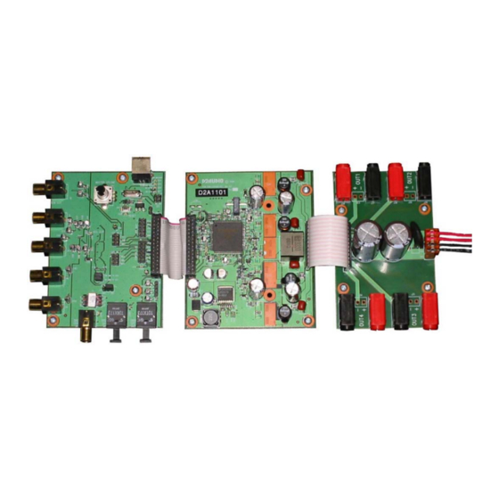
CONTROL I/O BOARD FIGURE 23. DIGITAL/ANALOG AUDIO/CONTROL I/O BOARD, AMPLIFIER BOARD, AND OUTPUT BOARD USB Interface A USB interface is provided on the TXS25-4 evaluation platform to provide communications between the TXS25-4 amplifier design and an external PC based system. The USB interface provides a means of upgrading the amplifier design system parameters, input sources, and DSP firmware. -
Page 25: Block Diagram
7600 B Capital Of Te 7600 B Capital Of Te 7600 B Capital Of Te Optional for Eval Kit Suite 130 Suite 130 Suite 130 Austin, TX 78731 Austin, TX 78731 Austin, TX 78731 Title Title Title TXS25-4 Reference TXS25-4 Reference TXS25-4 Reference... - Page 26 Austin, TX 78731 Austin, TX 78731 Austin, TX 78731 Boot Source IRQ [D:A] BOOT_EE/I2C nBOOT_EE/I2C Title Title Title TXS25-4 Reference TXS25-4 Reference TXS25-4 Reference System Enginering System Enginering System Enginering 2-wire ROM on GPIO6,7 0 1 1 1 Local Power Supplies Size...
- Page 27 1206 1206 Suite 130 Suite 130 Suite 130 Austin, TX 78731 Austin, TX 78731 Austin, TX 78731 Title Title Title TXS25-4 Reference TXS25-4 Reference TXS25-4 Reference System Engineering System Engineering System Engineering -25V Size Size Size Document Number Document Number...
- Page 28 1206 1206 Suite 130 Suite 130 Suite 130 Austin, TX 78731 Austin, TX 78731 Austin, TX 78731 Title Title Title TXS25-4 Reference TXS25-4 Reference TXS25-4 Reference System Engineering System Engineering System Engineering -25V Size Size Size Document Number Document Number...
- Page 29 Suite 130 Suite 130 Vout = +6.4V : R2 = 4.29K Austin, TX 78731 Austin, TX 78731 Austin, TX 78731 Title Title Title TXS25-4 Reference TXS25-4 Reference TXS25-4 Reference System Engineering System Engineering System Engineering Size Size Size Document Number...
- Page 30 7600 B Capital Of Texas HWY N Suite 130 Suite 130 Suite 130 Austin, TX 78731 Austin, TX 78731 Austin, TX 78731 Title Title Title TXS25-4 Reference TXS25-4 Reference TXS25-4 Reference System Engineering System Engineering System Engineering Size Size Size Document Number...
- Page 31 7600 B Capital Of Texas HWY N GNDB Suite 130 Suite 130 Suite 130 Austin, TX 78731 Austin, TX 78731 Austin, TX 78731 Title Title Title TXS25-4 Reference TXS25-4 Reference TXS25-4 Reference System Engineering System Engineering System Engineering Size Size Size Document Number Document Number Document Number Breakaway - USB &...
- Page 32 7600 B Capital Of Texas HWY N GNDB Suite 130 Suite 130 Suite 130 Austin, TX 78731 Austin, TX 78731 Austin, TX 78731 Title Title Title TXS25-4 Reference TXS25-4 Reference TXS25-4 Reference System Engineering System Engineering System Engineering Size Size Size Document Number Document Number...
- Page 33 7600 B Capital Of Texas H Suite 130 Suite 130 Suite 130 Austin, TX 78731 Austin, TX 78731 Austin, TX 78731 Title Title Title TXS25-4 Reference TXS25-4 Reference TXS25-4 Reference System System System Size Size Size Document Number Document Number...
- Page 34 7600 B Capital Of Texas HWY N Suite 130 Suite 130 Suite 130 Austin, TX 78731 Austin, TX 78731 Austin, TX 78731 Title Title Title TXS25-4 Reference TXS25-4 Reference TXS25-4 Reference System Engineering System Engineering System Engineering Retrofit Option Size Size...
- Page 35 • Updated Intersil and D2Audio name references. Leveraged existing TXS25-2 evaluation document and • Updated and revised photos to better represent platform updated with basic TXS25-4 information including signal flow, • Added updates to power supply references. connection diagrams, jumper configurations, schematics, and •...
-
Page 36: Sales Offices
10. It is the responsibility of the buyer or distributor of Renesas Electronics products, or any other party who distributes, disposes of, or otherwise sells or transfers the product to a third party, to notify such third party in advance of the contents and conditions set forth in this document.
Need help?
Do you have a question about the TXS25-4 and is the answer not in the manual?
Questions and answers