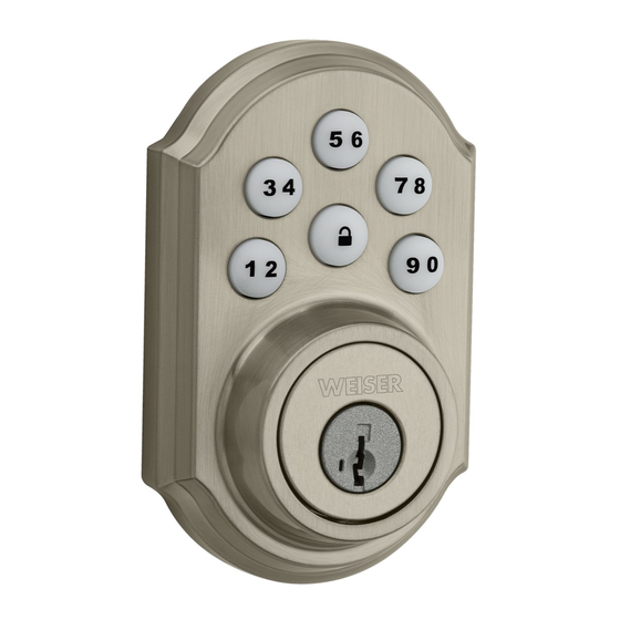
Weiser Smartcode 5 Installation And User Manual
Touchpad electronic level
Hide thumbs
Also See for Smartcode 5:
- Installation manual (2 pages) ,
- Installation and user manual (4 pages)
Table of Contents
Advertisement
66077 001 Rev 01
GED1455
Z Wave® Plus
Installation and User Guide
Required tools
Ruler
Phillips head screwdriver
Additional Tools (depending on application)
Hammer
Wood block
1
Prepare the door and check dimensions
If drilling a new door, use the supplied template and the complete
door drilling instructions available at www.weiserlock.com/doorprep.
A
Measure to con irm that the hole in
the door is 54 mm (2 1/8 in).
See
note
below*
54 mm
2 1/8 in
*If you are installing this lever below
an existing lock or you plan to install a
lock above this lever, make sure that the
distance between holes is at least 165 mm
(6 1/2 in).
2
Install the latch and strike
A
Hold the latch in front of the door hole, with the latch
face lush against the door edge.
A
B
Is the semi-circular hole of the latch centred in
the door hole?
YES
or
No adjustment is required.
Move the pin to
Proceed to next step.
extend the latch.
Weiser
Technical Support
1 800 501 9471
www.weiserlock.com
B
Measure to con irm that the backset is
either 60 or 70 mm (2 3/8 or 2 3/4 in).
b a
60 or 70 mm
c k
s e
t
2 3/8 or 2 3/4 in
C
Adjust the latch face (if needed).
For square corners
Proceed to step 2D.
lush
For round corners
1. Remove square corner faceplate.
A
NO
2. Install round corner faceplate.
For doors without chiselled edge
1. Remove plates.
A
A
2. Install drive-in collar.
A3
1 / 4
Parts in the box
Latch
Exterior
Assembly
F
A
A2 A3
Strike
Mounting
Plate
C
Keys
Spindle
SmartKey
Tool
E
F2
Batteries
Levers
Y2
Y1
C
Measure to con irm that the hole in
the door edge is 25 mm (1 in).
25 mm
1 in
actual
size
D
Is the door edge chiselled?
Ensure A2
snaps into
A2
place.
E
Install strike on the door frame.
Interior
Assembly
M
L
K
Fasteners
G
26298
N
P
Z
H
22044
T
27526
64156
J
U
V
D
Measure to con irm that the door is
between 35 and 44 mm (1 3/8 and
1 3/4 in) thick.
35 – 44 mm
1 3/8 – 1 3/4 in
N
P
YES
NO
or
chiselled
not
chiselled
slant of latch
slant of latch
bolt faces
bolt faces
door frame
door frame
N (2x)
wood block
C
P (2x)
door frame
Advertisement
Table of Contents

Summary of Contents for Weiser Smartcode 5
- Page 1 Strike Mounting Fasteners Installation and User Guide Plate 26298 Keys Spindle SmartKey Required tools Tool 22044 Weiser Technical Support Ruler Phillips head screwdriver Batteries Levers 1 800 501 9471 Additional Tools (depending on application) 27526 64156 www.weiserlock.com Hammer Wood block...
- Page 2 actual Install the exterior keypad, mounting plate, and spindle size Install exterior keypad. Route cable through mounting plate. Secure mounting plate with Install spindle. supplied screws. keep parallel to edge of door cable goes rounded edge over latch faces latch T (2x) tighten latch...
- Page 3 For enhanced security, a mastercode may be used when adding and deleting user codes. For more information about the mastercode, download the Programming and Troubleshooting Guide on the SmartCode 5 Lever page at www.weiserlock.com. Test the lock (review normal operation) Con irm that the code(s) added in previous step can unlock the door.
- Page 4 Z Wave device. And, regardless of the vendor, always powered nodes may act as a repeater for Kwikset/Weiser/Baldwin products. performance grades to suit the application. In order to enhance security and reduce risk, you should consult a quali ied locksmith or other security professional.
- Page 5 1. Association Groups The lock supports 2 association groups. Per Z-Wave Plus requirements, group 1 is assigned to the Lifeline group. The Lifeline group supports the following unsolicited messages: Battery Report Door Lock Operation Report Notification Report Device Reset Locally Notification Group 2 is available for all Notification Reports and can be used to send notifications to at most 5 other nodes.
- Page 6 The door lock will only retain valid user code types (0x01, 0x03, and 0x04). All other values will be ignored. If a user code does not exist for the corresponding configuration parameter, the lock will report a value of 0xFF. Any attempts to change the user code for a non-existent user will be ignored.
- Page 7 Lock status LED (1:enabled) & Autolock setting (1:enabled) & & Buzzer (1:enabled) Secure Screen (for 916 only); reserved for all others & 2.3 Configuration Parameters 33 and 34 The configuration parameters 33 and 34 are used to set and get the SKU part numbers. The SKU is made up of 8 bytes.
- Page 8 3. Inclusion Procedures Power the lock by placing the battery pack into the lock On the controller, select the option to add a device. On the lock, press button ‘A’. The red LED will illuminate until the add request has been processed. 4.


Need help?
Do you have a question about the Smartcode 5 and is the answer not in the manual?
Questions and answers