Table of Contents
Advertisement
1. SPECIFICATIONS .............................. 2
2. ACCESSORIES ................................. 2
3. AUTOMATIC ICE MAKING .................. 3
1. PART NAMES .................................... 4
2. INTERNAL STRUCTURE ..................... 5
3. FLOW OF COOL AIR ........................... 6
4. TEMPERATURE DISTRIBUTION ............ 7
2. INNER DIMENSIONS ........................... 9
[4] ELECTRICAL CIRCUIT DIAGRAMS ............ 10
1. WIRING DIAGRAM .............................. 10
2. ELECTRIC ACCESSORIES LAYOUT ...... 11
2. MODE FOR DISPLAY ........................... 14
1. R600A PRECAUTIONS ........................ 15
SERVICE MANUAL
Refrigerator-freezer
MODEL
Refrigerant; R600a
Refer to "REFRIGERATING-CYCLE REPAIR MANUAL" for handling this refrigerant.
CONTENTS
3. REFRIGERATION CYCLE DIAGRAM ...... 15
1. SELF-DIAGNOSIS MODE ..................... 18
COMPARTMENT DISASSEMBLY ......... 29
5. HOW TO REMOVE OP. PWB ASS'Y ...... 32
6. HOW TO REMOVE TERMINAL BOX ...... 33
7. HOW TO INSTALL R-SUB PACKING ...... 33
10. MAIN PARTS ASSEMBLY ..................... 36
Parts Guide
No.S0311SJF50XTFT
SJ-XF50X-T
DESTINATION
This document has been published to be used for
after sales service only.
The contents are subject to change without notice.
F
Advertisement
Table of Contents

Related Manuals for Sharp SJ-XF50X-T


Summary of Contents for Sharp SJ-XF50X-T
-
Page 1: Table Of Contents
SERVICE MANUAL No.S0311SJF50XTFT Refrigerator-freezer MODEL SJ-XF50X-T DESTINATION Refrigerant; R600a Refer to "REFRIGERATING-CYCLE REPAIR MANUAL" for handling this refrigerant. CONTENTS [1] PRODUCT SPECIFICATIONS 2. TABLE OF R600A CHARACTERISTICS … 15 1. SPECIFICATIONS ………………………… 2 3. REFRIGERATION CYCLE DIAGRAM …… 15 2. ACCESSORIES …………………………… 2 3. -
Page 2: Product Specifications
SJXF50XT PRODUCT SPECIFICATIONS SPECIFICATIONS Item SJ-XF50X-T Rated voltage/Rated frequency 110V~60Hz Rated current Rated power input of heating systems Defrosting input Defrosting heater input Outer dimensions (mm) 685 x 699 x 1820 Width×Depth×Height Rated total storage volume 501L (17.7 cu.ft.) Refrigerator compartment 268L (9.47 cu.ft.) -
Page 3: Automatic Ice Making
SJXF50XT Freezer compartment (Upper) Freezer case (Upper) Stainless tray Freezer compartment (Lower) Freezer case (top) Freezer case (bottom) Ice compartment Ice storage box Noise-proof sheet Ice scoop Vegetable compartment Vegetable case Fruit case Pet case Stainless tray Other Accessories and Printed Materials Foot grille Operation manual Warranty card... -
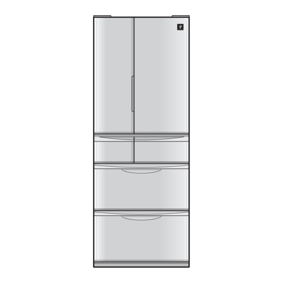
Page 4: Designation Of Various Parts
SJXF50XT [2] DESIGNATION OF VARIOUS PARTS PART NAMES Parts names in parentheses "[ ]" are denominations used in the Operation manual. Plasmacluster unit Cool plate R shelf Door pocket(left) Door pocket(right) Egg case Free set shelf Egg tray Case Chilled case Water tank C case tray Bottle pocket(left) -
Page 5: Internal Structure
SJXF50XT INTERNAL STRUCTURE... -
Page 6: Flow Of Cool Air
SJXF50XT FLOW OF COOL AIR Flow of Cool air Refrigerator compartment Freezer compartment (upper) Ice compartment Freezer compartment (lower) Vegetable compartment Side view Front view When Plasmacluster ion is in operation. Refrigerator compartment Freezer Ice compartment compartment (upper) Freezer compartment (lower) -
Page 7: Temperature Distribution
SJXF50XT TEMPERATURE DISTRIBUTION Approx.2 ~ 5°C Approx.3 ~ 7°C Approx.3 ~ 7°C Approx.0 ~ 2°C Approx.-17 ~ -19°C Approx.-18 ~ -20°C Approx.-18 ~ -20°C Approx.3 ~ 8°C ● The temperatures above are indications under the condition of no food inside, doors closed and surrounding temperature is 30 after stabilized the inside temperature. -
Page 8: Dimensions
SJXF50XT [3] DIMENSIONS OUTER DIMENSIONS AND CLEARANCE (UNIT:mm) More than More than More than More than 661.5 Moving wheels back side 632.5 Moving wheels front side 626.5 (Adjustable feet) 135° 135°... -
Page 9: Inner Dimensions
SJXF50XT INNER DIMENSIONS • The dimensions between shelves can be changed by setting the shelves on the other rails. -
Page 10: Electrical Circuit Diagrams
SJXF50XT [4] ELECTRICAL CIRCUIT DIAGRAMS WIRING DIAGRAM Compressor Protector Terminal box Door Door switch switch Reactance (left) (right) (left) Indicator Source cord motor g Temp. Plasmacluster control unit Motor Valve turret EECON-INV (right) Humidity sensor F proximity Main PWB D-fan motor PCI switch Gear V thermistor... -
Page 11: Electric Accessories Layout
SJXF50XT ELECTRIC ACCESSORIES LAYOUT... -
Page 12: Precautions For Using Lead-Free Solder
SJXF50XT PRECAUTIONS FOR USING LEAD-FREE SOLDER 1) Employing lead-free solder The PWB of this model employs lead-free solder. This is indicated by the "LF" symbol printed on the PWB and in the service manual. The suffi x letter indicates the alloy type of the solder. Example: Indicates lead-free solder of tin, silver and copper 2) Using lead-free wire solder... -
Page 13: Electrical System Specifications
SJXF50XT [5] ELECTRICAL SYSTEM SPECIFICATIONS FUNCTIONAL PART SPECIFICATIONS Part Name Specifi cations Function Model No.: 4715JL-09W-S37 For cooling Fan motor F Rating: DC15V (For freezer compartment) Power Input: 1.05W (Vs:2.6V) Model No.: 4515JL-09W-S10-G01 For condensing Fan motor g Rating: DC12V (Out side refrigerator) Power Input: 1.2W Model No.: D09F-12SM20(EX) -
Page 14: Mode For Display
SJXF50XT MODE FOR DISPLAY 2-1. How to set the product in this mode • Open the doors of the refrigerator compartment and the ice compartment within 2 minutes after turning ON the power to the main unit, and press and hold the [ 冷凍 ] button for 5 seconds or longer. 2-2. -
Page 15: Refrigeration Cycle System Specifications
SJXF50XT [6] REFRIGERATION CYCLE SYSTEM SPECIFICATIONS R600A PRECAUTIONS • Do not use any refrigerant other than R600a. • Gas leak testers for HFC-134a, CFC-12, HCFC-22, etc., cannot be used. • A special tool is used for the R600a cycle. TABLE OF R600A CHARACTERISTICS Refrigerant saturated vapor pressure table R600a (Unit) Temperature: °C, Pressure: kgf/cm abs Temperature... -
Page 16: Schematic Diagram
SJXF50XT 3-2. Schematic diagram Side Bottom condenser Side condenser L condenser R Dryer Back condenser condenser Charge pipe R-valve ass’y (High presure side) Extra cond. unit Extra cond. unit kit Discharge pipe kit Suction pipe Suction connector Evaporator Compressor Charge pipe (Low presure side) 3-3. - Page 17 SJXF50XT 3-4. Specifi cations of Refrigerant Valve Operation Modes and operating conditions of refrigerant valve (3-way valve) Valve is fully closed: • This mode is used in compressor OFF status. Only fine capillary is opened: • During normal cooling operation Only wide capillary is opened: •...
-
Page 18: Troubleshooting
SJXF50XT [7] TROUBLESHOOTING SELF-DIAGNOSIS MODE 1-1. Outline • The self-diagnosis mode stores fault data for 5 days in the past (including “today”), and displays them by the date in the order of occurrence. Self-diagnosis data to be displayed Storage of self-diagnosis result Current fault Fault history All faults that have currently occurred... - Page 19 SJXF50XT Operation in the self-diagnosis mode • The compressor is forcedly turned ON. (Excepting a period of defrosting operation and compressor ON delay time) • The cooling, condenser and R-fan motors are forcedly turned ON. (These motors will be forcedly turned ON even while the compressor is OFF. However, when the door is opened, the motors other than the condenser fan motor are kept OFF.) •...
- Page 20 SJXF50XT <Example of button operations and self-diagnosis display> * During self-diagnosis mode input, the “current” fault is displayed. Press Press Press [During mode input] [冷凍]. [冷凍]. [冷凍]. “1-day before” “2-day before” “Current” fault “Current” fault history fault history fault history Press Display of the Display of the fault...
- Page 21 SJXF50XT 1-3. Self-diagnosis display [Table 1] (Problems and problem history related to thermistors, auto ice cube maker, inverter,etc.) indicates a problem, indicates the status. Lamp indication: Lit = , Blinking = (0.5-sec. ON/0.5-sec. OFF) Buzzer: Only when a fault is indicated in the current fault display, the buzzer continuously sounds (0.2-sec. ON/1.8-sec. OFF). Lamp indication (Temperature control LED) Description ExplanationofStatuses...
-
Page 22: Forced Stopping Of Door Alarm Buzzer
SJXF50XT FORCED STOPPING OF DOOR ALARM BUZZER * Used when the door switch is faulty. How to stop • While the door-open buzzer sounds, press the [ 冷蔵室 ] and [ 冷凍室 ] buttons simultaneously and hold them for 3 seconds or longer. -
Page 23: Inspection Flowchart And Repair Items
SJXF50XT INSPECTION FLOWCHART AND REPAIR ITEMS • During check of the PWB circuits, use thorough caution not to get electric shock. • To check resistance of electric parts, be sure to disconnect the power supply plug. (Turn OFF the power supply.) Problem Self-diagnosis display Check/inspection point... - Page 24 SJXF50XT Problem Self-diagnosis display Check/inspection point Action on error detection R-thermistor fault 1) Connector insertion check (Main PWB, intermediate 1) Correct the installation. connector) 2) Replace the thermistor. 2) Thermistor resistance check (Check the value in the 3) Replace the main PWB. thermistor characteristic table.) 3) If the above check results are normal: R-fan motor fault...
-
Page 25: Plasmacluster Ok/Ng Judgment
SJXF50XT Plasmacluster OK/NG Judgment Judgment procedure Disconnect the power supply, and keep the refrigerator compartment door opened for 5 minutes or longer to raise the temperature in the refrigerator compartment. After closing the refrigerator compartment door, connect the power supply, and turn ON the plasmacluster. (When the plasmacluster is turned ON, the blue LED in the compartment is ON.) Check the ion at the PCI discharge port with the ion measuring instrument. -
Page 26: Disassembly/Assembly
SJXF50XT [8] DISASSEMBLY/ASSEMBLY GENERAL DISASSEMBLY SEQUENCE Refrigerator compartment Accessories (Shelves・Chilled case・Water tank) Partition support・C-shelf ass’y Duct RT ass’y R-shower duct ass’y PCI box ass’y R-C box ass’y・Connector cover R Pipe cover Freezer compartment Accessories (Ice storage box・ Freezer cases) 2-1-2 SW cover (When replacing F proximity switch) 2-1-2... -
Page 27: Refrigerator Compartment Disassembly
SJXF50XT REFRIGERATOR COMPARTMENT DISASSEMBLY Main component Contained parts RC box ass'y Gear pump, R-thermistor, damper Pipe cover R-shower duct ass'y Catalyzer D-PCI box ass'y Plasmacluster unit, indicator PWB, D-fan motor PCI, Motor, O catalyzer Remove the accessories (shelf, chilled case, etc.). How to remove chilled lock Unhook two claws (if they are tight and stuck, insert Remove the chilled shelf stopper. - Page 28 SJXF50XT Remove the four locations of the inner protrusion. Remove the connector cover R (Screw at 1 place, When the protrusions are unhooked, pull it downward Claws at 2 places), and disconnect four connectors. to remove it. □ : claw ○...
-
Page 29: Freezer Compartment/Ice Compartment Disassembly
SJXF50XT Cut A-Sealer R-C box insu A along the joint of R-C Remove the damper. box insu A/B (dotted line). Pull out the pipe cover. □ : claw R-C box insu A Damper A-sealer Pipe cover R-C box insu B FREEZER COMPARTMENT /ICE COMPARTMENT DISASSEMBLY Main component Contained parts... - Page 30 SJXF50XT • Remove the C-part. FI-FK. Top of the EV cover (When replacement of F-LED PWB ass’y) □ Remove three screws and one claw, and push the : claw PWB backward. : screw EV cover ass’y C-part. FI-FK Remove the Heater. (Replacement procedure) CAUTION: The heater is a charged and heating part.
-
Page 31: Vegetable Compartment Disassembly
SJXF50XT Remove the aluminum tape that fastens the lead VEGETABLE COMPARTMENT wire to the drip tray. DISASSEMBLY Screw Heater AL Screw Main component Contained parts Damper, G-thermistor (V-thermistor) Remove the V door. Remove the Damper cover. Remove one screw. Pull the Damper cover while inserting a flathead Aluminum tape screw driver, etc., to have some gap. -
Page 32: How To Remove Op. Pwb Ass'y
SJXF50XT How to install Damper cover • Drive in the Damper cover after fi tting claws at two places while running through the slit under left. • Attach one screw. Damper cover : claw HOW TO REMOVE OP. PWB ASS'Y Remove the PWB cover. -
Page 33: How To Remove Terminal Box
SJXF50XT HOW TO REMOVE TERMINAL BOX • Remove screws (2 places). Terminal box ○ : screw HOW TO INSTALL R-SUB PACKING • Fasten the R-sub packing with the claws of the R-door ass’y (front: 8 places, back: 6 places). First, claw either top or bottom of the packing to fasten it, and then claw the remaining points in sequence. (The fi... -
Page 34: How To Install Duct Rt Ass'y Cover
SJXF50XT HOW TO INSTALL DUCT RT ASS'Y COVER Insert two claws (located in the center) of the Duct RT ass'y cover into the holders at the ceiling inside the refrigerator compartment. 2. After inserting two claws at the right and left side into the holders, tuck the Duct RT rivets into the holders. ①... -
Page 35: Adjustment Of R-Door(Double Door)
SJXF50XT ADJUSTMENT OF R-DOOR(DOUBLE DOOR) If the right and left door positions are different: Adjustment with the adjustable legs: • When the right door is lower than the left one, extend the adjusting legs on the right side (until the adjusting legs on the opposite side slightly leave the fl oor surface). •... -
Page 36: Main Parts Assembly
SJXF50XT MAIN PARTS ASSEMBLY EV cover ass’y <Components> A-sealer EV. cover C A-sealer EV. cover D A-sealer F Fan motor F EV.cover sealer N A-sealer EV. cover DEF-thermistor F-thermistor A-sealer EV. cover E Duct heater L-band C A-sealer EV. cover B EV.cover AL EV.cover EV-insulation A... - Page 37 SJXF50XT Attach the A-sealer EV. cover B to the harness of duct heater. Duct heater EV-insulation B A-sealer EV. cover B Wrapping the A-sealer EV. cover B Duct heater Put it on so that there is no space between the sealer and the insulation. Attachment side of heater EV-insulation B...
- Page 38 SJXF50XT Mounting the F-thermistor, fan motor F, and EV. insulation ass’y • Fit the EV. insulation ass’y in the EV. cover. • Wind the EV. cover sealer N on the harness. • Mount the F-thermistor and fan motor F to the EV. cover. EV.cover F-thermistor EV.cover sealer N...
- Page 39 SJXF50XT Mounting the fan louver • Mount the DEF-thermistor, and fasten the harness of the fan motor F and the DEF-thermistor with the L-band C. • Wind the EV. cover sealer N on the lead wire of the DEF-thermistor and the fan motor F. •...
- Page 40 SJXF50XT R-shower duct ass’y <Components> A-sealer R-S duct B R-shower duct cover T A-sealer R-S duct C Cool plate Center cover L R shower duct insu R-shower duct cover B Center cover R Catalyzer <Assembling procedure> Attach the A-sealer R-S duct B and C to the R-shower duct insu. R shower duct insu.
- Page 41 SJXF50XT Attach the R-shower duct cover T and B to the cool plate. (Apply the claw securely.) Fit the Assembly of Step 1 to Assembly of Step 2. A-sealer R-S duct C A-sealer R-S duct B (Y) A-sealer R-S duct B (Y) R-shower duct cover T Hook the claw.
- Page 42 SJXF50XT RC box ass’y <Components> Joint pipe Joint packing Packing holder Gear pump R-thermistor A-sealer RCBOX A A-sealer RCBOX B R-C box insu.A R-C box insu.B R-C box Pump cushion Damper <Assembling procedure> Insert the joint packing in the gear pump. •...
- Page 43 SJXF50XT Fasten the packing holder to the assembly of Step 2 with two screws. • Tightening torque is 3.5 to 4.5 kgf/cm (0.34 to 0.44 Nm). • Insert the gear pump harness in the groove of the R-C box, and bend the R-C box hinge so that the Claw is securely engaged.
- Page 44 SJXF50XT Attach the A-sealer RCbox A and RCbox B to the assembly of Step 5. • Attach the sealer securely so that it will not rise. A-sealer RCbox A R-C box insu. A Paste the sealer along the edge of insulation. A-sealer RCbox A R-C box insu.
- Page 45 SJXF50XT C-part. FI-FK <Components> C-part.FI-FL Proximity switch C insu. FI C-part. FI-FR A-sealer FIA A-sealer FIC A-sealer FIB A-sealer FI <Assembling procedure> Put the A-sealer on the C insu. FI. Put it on so that there is no space between the sealer and the insulation. Start of sealing Start of sealing...
- Page 46 SJXF50XT Mount the assembly of Step 1 to the assembly of Step 2. C-part.FI-FL C insu.FI Attach the C-part. FI-FR to the assembly Step 3 and screw it on. • Attach the A-sealer FIA, B and C. Sealing standard A-sealer FIA C-part.FI-FL Sealing standard C-part.FI-FR...
- Page 47 SJXF50XT D-PCI box ass’y <Components> A-sealer D PCI box A D-damper holder Motor A-sealer PCI fan A-sealer d-damper B Plasmacluter unit D-damper flap O catalyzer D-fan motor PCI Plate A-sealer d-damper A Absorbent rubber A Absorbent rubber B D-PCI cover Indicator PWB K-GF60X D-PCI box ass’y <Assembling procedure>...
- Page 48 SJXF50XT Attach A-sealer D-damper A and B. • Attach A-sealer D-damper A and B to the D-damper flap. D-damper flap D-damper flap A-sealer d-damper A When attaching A-sealer D-damper B, do not cover the rib of the D-damper flap When attaching A-sealer D-damper A, periphery.
- Page 49 SJXF50XT Mount the assembly of Step 3 and the D-PCI fan cover to the assembly of Step 4, and attach A-sealer PCI box. D-PCI cover Hook the claw on the D-PCI box to the D-PCI cover (at 1 place). A-sealer D-PCI box A A-sealer D-PCI box A Hook the claw on the D-PCI box...
- Page 50 SJXF50XT Ice maker ass’y T-SK <Components> I-grill Ice cube maker Ice cube tray AT Harness cover Ice maker ass’y Thermistor Thermistor cover Sealer Plate Ice cube heater Ice senser Ice heater cover T L-band C <Assembling procedure> Put Thermistor on back side of Ice cube tray AT. •...
- Page 51 SJXF50XT Cover Ice cube tray AT with Ice heater cover T. * Set Ice heater cover T so as to " " marking side is on axis of Ice cube tray AT. * Tightening toruque is 0.5N•m. Marking “ ” Ice heater cover T Screw Axis...
- Page 52 SJXF50XT Get the harness of the ice make thermistor in the assembly Step 5 through the holes in front of and at the back of the I-grill. • Make sure to keep the end face of the protective tube next to the ice cube tray covered with the ice heater cover T. (Do not pull the harness strongly.) Ice cube tray AT Ice maker ass’y harness...
- Page 53 SJXF50XT Bundle the harness with the L band C and fix it to the I-grill. (1) Bundle the ice maker thermistor and the protective tube of the ice cube heater with the L band C and fi x them to the I-grill.
- Page 54 SJXF50XT Fruit case ass'y <Components> K handle K handle cover K lock spring K handle cover label K lock rever Fruit case K handle support K handle arm K handle base Lock unit <Assembling procedure> Install the K handle arm and K lock rever to the K handle base. K handle arm K lock rever K handle base...
- Page 55 SJXF50XT Combine assembly Step 1 and Step 2. Insert the claw A to the form B firmly. Confi rm that the tip of the K lock spring is inserted into the cross rib of the K lock lever. K lock spring K lock rever Claw A Claw A...
- Page 56 SJXF50XT Hook assembly Step 5 to the fruit case and rotate it. Be careful not to scratch parts against others. Fruit case Put the dent of K handle base from the bottom to the convex of fruit case. Hook two claws on the K handle base to the fruit case. Make sure to insert them properly. Fruit case K handle base Two claws...
- Page 57 SJXF50XT Fan motor G ass’y <Components> W-sealer-g fan Fan motor G W-sealer-g fan W-sealer-g fan hnss <Assembling procedure> Attach the W-sealer G fan to the fan motor G. • When attaching the W-sealer G fan, do not stretch it strongly. Attach the W-sealer G fan harness.
-
Page 58: Parts List
PARTS LIST Refrigerator-freezer MODEL SJ-XF50X-T CONTENTS SJ-XF50X-T DOOR SJ-XF50X-T CYCLE SJ-XF50X-T CABINET1 SJ-XF50X-T OTHER PARTS SJ-XF50X-T CABINET2 INDEX SJ-XF50X-T CABINET3 This document has been published to be used for after sales service only. The contents are subject to change without notice. - Page 59 SJXF50XT [1] SJ-XF50X-T DOOR 3-17-2 3-17-3 3-18 3-40 3-15 3-11-2 3-15 3-17 3-11-3 5-4-3 3-11 5-4-2 3-12 5-12 5-4-1 3-14 3-19 5-4-4 3-13 5-38 5-4-6 3-17-1 3-37 5-4-5 3-39 3-28 5-40 5-37 3-11-1 3-35 5-23 5-25 5-16-1 5-16-2 5-23 5-16...
- Page 60 SJXF50XT PRICE PART PARTS CODE DESCRIPTION RANK MARK RANK [1] SJ-XF50X-T DOOR FPWB-B099CBKZ Op. Pwb DFRM-A130CBKZ F-frame ass'y FDORFC372CBKZ F-door ass'y PPACGA314CBZA F-sub packing PPACGA315CBZA F-sub packing DFRM-A131CBKZ F-t frame ass'y 3-5-1 LFRM-A444CBTA Fi frame l 3-5-2 LFRM-A445CBTA Fi frame r...
- Page 61 SJXF50XT PRICE PART PARTS CODE DESCRIPTION RANK MARK RANK [1] SJ-XF50X-T DOOR 5-25 UPOKPA344CBFC Door pocket 5-26 UYOK-A705CBFB Pet case 5-33 UYOK-A747CBWZ V case sus 5-37 UYOK-A786CBWZ C case tray 5-38 PCOV-A519CBFA C case cover 5-40 PPACGA388CBFA C case packing...
- Page 62 SJXF50XT [2] SJ-XF50X-T CABINET1 2-105 2-104 2-82 2-25 2-23 2-23-5 1-32 2-14 4-11 2-140 2-22 2-23-2 2-101 2-16 2-23-4 2-15 2-145 4-10 2-17 2-101 2-24 2-23-3 4-10 2-138 2-90 1-26 2-26 2-81 1-23 2-83 2-88 1-26 2-119 2-118 2-100 2-84...
- Page 63 SJXF50XT PRICE PART PARTS CODE DESCRIPTION RANK MARK RANK [2] SJ-XF50X-T CABINET1 DTHM-A034CBKZ Damper RH-HXA154CBZZ Thermistor RHETBA384CBZZ Ice cube heater 1-23 QSW-LA031CBZZ Proximity switch 1-24 FACC-A176CBKZ Source cord-k 1-26 QSW-PA079CBEA Door switch 1-31 RH-HXA100CBZZ G-thermistor 1-32 RDTC-A001CBZZ Humidity sensor ZPAPRBPCOVERY...
- Page 64 SJXF50XT [3] SJ-XF50X-T CABINET2 2-75 2-76 2-68 2-67 2-70 2-73 2-71 2-69 2-38 2-33 2-37 2-72 2-102 1-28 1-12 2-41 2-42 2-103 1-13 2-35 2-94 2-36 2-39 2-34 2-146 2-52 2-53 This shows the part that exchange is necessary for a set.
- Page 65 SJXF50XT PRICE PART PARTS CODE DESCRIPTION RANK MARK RANK [3] SJ-XF50X-T CABINET2 FHETBA277CBZZ Heater DTHM-A031CBKZ Damper ass'y 1-12 FGER-A015CBZZ Gear pomp 1-13 RH-HXA122CBZZ R-thermistor 1-15 RH-HXA113CBZZ F-thermistor 1-16 RH-HXA130CBZZ Def-thermistor 1-17 RMOTRA138CBZZ Fan motor f 1-18 RHETBA400CBZZ Duct heater 1-19...
- Page 66 SJXF50XT [4] SJ-XF50X-T CABINET3 This shows the part that exchange is necessary for a set. 2-32 2-122 1-29 2-129 2-31 2-123 2-125 2-149 1-11 2-128 2-29 2-30 2-28 1-10 2-60-4 2-27 2-60-1 2-60-3 2-60-3 2-60-2 2-60 2-133 2-133 This shows the part that exchange is necessary for a set.
- Page 67 SJXF50XT PRICE PART PARTS CODE DESCRIPTION RANK MARK RANK [4] SJ-XF50X-T CABINET3 CKITTA216AKKZ Plasmacluster unit 1-10 FPWB-B085CBKZ Indicator pwb 1-11 RMOTRA139CBZZ D-fan motor pci 1-22 FPWB-B219CBKZ Led pwb ass'y 1-29 RMOT-A007CBZZ Motor 2-27 PCOVPA708CBFA D-pci box a'ssy 2-28 PCOVPA709CBFA D-pci cover...
- Page 68 SJXF50XT [5] SJ-XF50X-T CYCLE 6-19 1-27 6-26 6-34 6-12 6-13 6-23 6-11 6-10 6-14 6-41 6-24 6-20 6-23 6-20 6-16 6-18 1-38 6-17 1-21 6-30 6-17 6-28 This shows the part that exchange is necessary for a set. PRICE PART...
- Page 69 Butyl 6-28 PSEL-E374CBZZ W-sealer-g-fan-hnss 6-30 PSEL-E624CBZZ A sealer casing b 6-34 PCONMA067CBZZ Extra cond.unit 6-41 PPIPCA906CBZZ Interface part [6] SJ-XF50X-T OTHER PARTS 90-1 CPADBA246CBKZ Bottom pad ass'y 90-2 CPADBA224CBKZ Top pad ass'y 90-3 SPAKCA811CBZZ Packing case 90-6 TINS-B482CBRZ Operation manual...
- Page 70 SJXF50XT INDEX PRICE PART PRICE PART PARTS CODE PARTS CODE RANK MARK RANK RANK MARK RANK LBND-0040AKE0 2-2-138 [ C ] LBND-A041CBZZ 3-2-43 CKITTA216AKKZ 4-1-9 CPADBA224CBKZ 6-90-2 LFRM-A444CBTA 1-3-5-1 LFRM-A445CBTA 1-3-5-2 CPADBA246CBKZ 6-90-1 LFRM-A451CBFA 1-3-5-3 [ D ] LFRM-A488CBFA 1-3-8-3 DFIL-A012CBKZ 1-5-4-6 LHLD-A414CBFA...
- Page 71 SJXF50XT PRICE PART PRICE PART PARTS CODE PARTS CODE RANK MARK RANK RANK MARK RANK PCOVPA720CBFZ 5-6-9 PSPAGA076CBFZ 5-6-23 PCOVPA721CBFA 3-2-68 PSRA-A083CBFA 1-5-11 PCOVPA722CBFA 3-2-69 PSRA-A091CBFA 2-2-23-5 PCOVPA726CBFA 2-2-141 PTNK-A033CBFA 1-5-4-5 PCOVPA785CBFA 2-2-23-2 PVLVEA007CBZZ 5-6-24 PCOVPA786CBFA 2-2-23-3 [ Q ] PFIL-A067CBZZ 4-2-125 QCNW-B635CBZZ...
- Page 72 EndPage COPYRIGHT © 2013 BY SHARP CORPORATION ALL RIGHTS RESERVED. No part of this publication may be reproduced, stored in retrieval systems, or transmitted in anyform or by any means, electronic, mechanical, photocopying, re- cording, or other wise, without prior written permission...
Need help?
Do you have a question about the SJ-XF50X-T and is the answer not in the manual?
Questions and answers