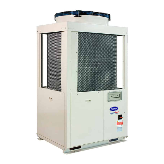
Carrier Aquasnap 30RB Series Installation, Operation And Maintenance Instructions

Carrier Aquasnap 30RB Series Installation, Operation And Maintenance Instructions

Air-cooled liquid chillers reversible heat pumps
Table of Contents

Advertisement

I N S TA L L AT I O N , O P E R AT I O N A N D
M A I N T E N A N C E
I N S T R U C T I O N S
Air-Cooled Liquid Chillers
Reversible heat pumps
30RB/30RQ 040R-160R
Rated cooling capacity 40-160 kW
R-32
* The availability of sizes and options depends on the country. Please contact your local commercial dealer for more information.
Translation of the original document

Advertisement

Table of Contents
loading

Summary of Contents for Carrier Aquasnap 30RB Series

  • Page 1 I N S TA L L AT I O N , O P E R AT I O N A N D M A I N T E N A N C E I N S T R U C T I O N S Air-Cooled Liquid Chillers Reversible heat pumps 30RB/30RQ 040R-160R...
  • Page 3: Table Of Contents

    CONTENTS 1 - INTRODUCTION AND SAFETY INSTRUCTIONS ........................5 2 - RECEIPT OF GOODS .................................. 5 2.1 - Checking the equipment received ............................. 5 3 - HANDLING AND POSITIONING ..............................6 3.1 - Handling ....................................6 3.2 - Positioning ....................................6 4 - DIMENSIONS, CLEARANCES, MINIMUM INSTALLATION DISTANCES ................
  • Page 4 CONTENTS 11 - MAIN COMPONENTS OF THE UNIT AND OPERATING CHARACTERISTICS ............... 34 11.1 - Compressors ..................................34 11.2 - Lubricant ....................................34 11.3 - Air-cooled exchanger ................................34 11.4 - Fans ....................................... 35 11.5 - Electronic expansion valve (EXV) ............................36 11.6 - Moisture indicator ..................................
  • Page 5: Introduction And Safety Instructions

    1 - INTRODUCTION AND SAFETY INSTRUCTIONS The units are designed to cool water (for coolers) and cool or reheat water (for reversible heat pumps) for the air conditioning and heating of buildings and industrial processes. They are designed to provide a very high level of safety and reliability, making installation, start-up, operation and maintenance easier and safer.
  • Page 6: Handling And Positioning

    3 - HANDLING AND POSITIONING 3.1 - Handling 3.2 - Positioning Carrier strongly recommends employing a specialised company The machine must be installed outdoors in a place that is not to unload the machine. accessible to the public and is protected against access by non- authorised persons.
  • Page 7: Dimensions, Clearances, Minimum Installation Distances

    4 - DIMENSIONS, CLEARANCES, MINIMUM INSTALLATION DISTANCES 4.1 - 30RB/30RQ 040R-080R, units with and without hydraulic module Key: NOTE: Non-contractual drawings. All dimensions are given in mm. When designing a system, refer to the certified dimensional Clearances required for maintenance and air flow drawings provided with the unit or available on request. Clearance recommended for coil removal Refer to the certified dimensional drawings for the location Water inlet...
  • Page 8: 30Rb/30Rq 090R-160R, Units With And Without Hydraulic Module

    4 - DIMENSIONS, CLEARANCES, MINIMUM INSTALLATION DISTANCES 4.2 - 30RB/30RQ 090R-160R, units with and without hydraulic module Key: NOTE: Non-contractual drawings. All dimensions are given in mm. When designing a system, refer to the certified dimensional Clearances required for maintenance and air flow drawings provided with the unit or available on request. Clearance recommended for coil removal Refer to the certified dimensional drawings for the location Water inlet...
  • Page 9: 30Rb/30Rq 040R-080R, Units With Water Buffer Tank Module

    4 - DIMENSIONS, CLEARANCES, MINIMUM INSTALLATION DISTANCES 4.3 - 30RB/30RQ 040R-080R, units with water buffer tank module Key: NOTE: Non-contractual drawings. All dimensions are given in mm. When designing a system, refer to the certified dimensional Clearances required for maintenance and air flow drawings provided with the unit or available on request. Clearance recommended for coil removal Refer to the certified dimensional drawings for the location Water inlet...
  • Page 10: 30Rb/30Rq 090R-160R, Units With Water Buffer Tank Module

    4 - DIMENSIONS, CLEARANCES, MINIMUM INSTALLATION DISTANCES 4.4 - 30RB/30RQ 090R-160R, units with water buffer tank module NOTE: Non-contractual drawings. Key: All dimensions are given in mm. When designing a system, refer to the certified dimensional Clearances required for maintenance and air flow drawings provided with the unit or available on request. Clearance recommended for coil removal Refer to the certified dimensional drawings for the location Water inlet...
  • Page 11: Free Spaces And Installing Several Units

    4 - DIMENSIONS, CLEARANCES, MINIMUM INSTALLATION DISTANCES 4.5 - Free spaces and installing several units In multiple-chiller installations (maximum of four units), the free space between the sides of the units should be increased to between 1000 and 2000 mm. The height of the solid surface must not exceed 2 m.
  • Page 12: Physical And Electrical Data For The Units

    5 - PHYSICAL AND ELECTRICAL DATA FOR THE UNITS 5.1 - Physical properties: 30RB/30RQ 40R-160R 30RB 040R 045R 050R 055R 060R 070R 080R 090R 100R 120R 140R 160R Sound levels Standard unit Sound power dB(A) 81,5 82,0 83,5 83,5 89,0 89,0 89,0 91,5 91,5 92,0 92,0 92,0 Sound pressure at 10 m dB(A) 50,0 50,5 52,0 52,0 57,5 57,5 57,5 60,0 60,0 60,5 60,5 60,5 Unit + option 15LS...
  • Page 13: Electrical Data Notes: 30Rb/30Rq 040R-160R

    5 - PHYSICAL AND ELECTRICAL DATA FOR THE UNITS 5.2 - Electrical data notes: 30RB/30RQ 040R-160R 30RB 040R 045R 050R 055R 060R 070R 080R 090R 100R 120R 140R 160R Power circuit supply Nominal voltage V-ph-Hz 400 - 3 -50 Voltage range 360 - 440 Control circuit supply 24 V via internal transformer...
  • Page 14: Electrical Data Notes For The Hydraulic Module

    5 - PHYSICAL AND ELECTRICAL DATA FOR THE UNITS 5.4 - Electrical data notes for the hydraulic module The pumps that are factory-installed in these units have motors with efficiency class IE3 for > 0.75 kW motors. The additional electrical  data required is as follows: Motors for unit high-pressure pumps (option 116R, 116S, 116V, 116W) Description 040R 045R 050R 055R 060R 070R 080R 090R 100R 120R 140R 160R Nominal efficiency at full load and nominal voltage 84,8 84,8 84,8 84,8 84,8 84,8 84,8 84,8 84,8 85,9 85,9 85,9 Rated efficiency at 75% of full load and nominal voltage...
  • Page 15 5 - PHYSICAL AND ELECTRICAL DATA FOR THE UNITS Motor for low-pressure single and dual pumps (option 116T, 116U, 116X, 116Y) Description 040R 045R 050R 055R 060R 070R 080R 090R 100R 120R 140R 160R Nominal efficiency at full load and nominal voltage 81,1 81,1 81,1 81,1 81,1 81,1 81,1 81,1 83,4 83,4 84,8 84,8 Rated efficiency at 75% of full load and nominal voltage 80,8 80,8 80,8 80,8 80,8 80,8 80,8 80,8 81,2 81,2 82,2 82,2 Rated efficiency at 50% of full load and nominal voltage...
  • Page 16: Electrical Data Notes For The Compressors

    5 - PHYSICAL AND ELECTRICAL DATA FOR THE UNITS 5.5 - Electrical data notes for the compressors I Max I start Compressor I Nom I Max (Un) LRA A (Un - 10%) option 25 (A) Phi nom. Phi Max. () DSF090 11,5 15,8...
  • Page 17: Comments On Electrical Data

    2. Compatibility for low-frequency conducted disturbances at class 2 levels as be considered, always contact your local Carrier representative. per the IEC 61000-2-4 standard: * The required protection level for this class is IP43BW (according to reference - Power supply frequency variation: +- 2Hz document IEC 60529). All AquaSnap 30RB/30RQ units are IP44CW and fulfil ...
  • Page 18: Electrical Connection

    6 - ELECTRICAL CONNECTION 6.3 - Power connection/disconnect switch Please refer to the certified dimensional drawings, supplied with  the unit. The power connection of the unit is carried out at a single point upstream of the unit’s disconnect switch. 6.1 - Power supply The earth connection must be made in the main electrical box on The ...
  • Page 19 6 - ELECTRICAL CONNECTION Table of minimum and maximum cable sections (per phase) for connection to the units Calculation of unfavourable case: Calculation of favourable case: - Conductors in ducts or multi- - multi-conductor cable wires in the conductor cables in closed conduits open air (routing modes 34 and 35, (standardised routing modes, °50, method E)
  • Page 20: Power Cable Access Routing

    6.7 - Electric and power reserve for the user voltage or excessive phase imbalance constitutes improper use and will invalidate the Carrier warranty. If the phase Control circuit power reserve: imbalance exceeds 2% for voltage, or 10% for current, contact...
  • Page 21: Application Data

    7 - APPLICATION DATA 7.1 - Operating range 7.1.1 - 30RB 040R-160R units Operating range - Standard unit Water type heat exchanger Minimum Maximum 30RB 040R-160R Water inlet temperature at start-up °C Water outlet temperature during operation °C Entering/leaving water temperature difference Charge partielle toutes tailles Part load all sizes...
  • Page 22: Minimum Heat Transfer Fluid Flow Rate (Units Without Factory-Fitted Hydraulic Module)

    7 - APPLICATION DATA NOTE: 7.5 - Minimum system water volume Units equipped with speed regulators (30RB/30RQ option 6B, Whichever system, water volume for the water loop (to be provided 12, 15LS, 28, 116V, 116W, 116X, 116Y). between the unit and any customer valves outside the machine) If the air temperature is below -10 °C and the unit has been is given by the formula deenergised for more than 4 hours, it is necessary to wait...
  • Page 23: Water Type Heat Exchanger Water Flow Rate

    7 - APPLICATION DATA 7.7 - Water type heat exchanger water flow rate Data applicable for pure water. 30RB 040R-160R units Dual-pump 30RB Minimum Maximum High pressure 040R 045R 050R 055R 060R 070R 080R 090R 100R 120R 140R 10,6 160R 11,2 (1) ...
  • Page 24: Water Connections

    8 - WATER CONNECTIONS 8.1 - Operating precautions and When connecting units to the water distribution pipe work, refer recommendations to the certified dimensional drawings supplied with the unit for the  dimensions and position of the water inlet and outlet connections. Before commissioning, make sure the hydraulic circuits are The piping must not transmit any axial or radial force to the connected to the appropriate heat exchangers.
  • Page 25: Hydraulic Connections

    8 - WATER CONNECTIONS 8.2 - Water connections The hydraulic module options are only compatible with closed loops. The use of the hydraulic module on open systems is prohibited. Schematic diagram of the hydraulic circuit without the hydraulic module Schematic diagram of the hydraulic circuit with the hydraulic module Op�on Option Op�on...
  • Page 26 8 - WATER CONNECTIONS Hydraulic module - sizes 039-080 Hydraulic module - sizes 090-160 Dual pump and buffer tank shown Dual pump and buffer tank shown Hydraulic module - sizes 040R-080R Hydraulic module - sizes 090R-160R Dual pump and buffer tank shown Dual pump and buffer tank shown...
  • Page 27: Units Without Hydraulic Module

    8 - WATER CONNECTIONS Refer to the diagram in the "Hydraulic connections" section for 8.3.2 - Hydraulic circuit cleaning procedure all references points mentioned in this chapter. • Open the valve completely (item 22). The water circulation pumps for the units in the range have been •...
  • Page 28: Units With Hydraulic Module And Fixed-Speed Pump (For Application With Brine Only)

    (item 6). rate or minimum frequency and this results in a higher • Remove the air from the circuit (items 5 and 14). pressure differential than the set point. • Repeat until all fouling is removed from the filter. Contact Carrier Service to discuss the implementation of the procedures set out below.
  • Page 29: Units With Hydraulic Module And Variable-Speed Pump - Temperature Differential Control

    (all valves open and all cooling coils active). Read the value of value than the set point. the !ow on the user interface and compare it with the theoretical Contact Carrier Service to discuss the implementation of the value of the range: procedures set out below.
  • Page 30 8 - WATER CONNECTIONS If the system is isolated by a valve, it is imperative to install a bypass as indicated below. Winter position Closed Unit Water network Open Closed IMPORTANT REMINDERS: Depending on the atmospheric conditions in your region, you need to: - Add an appropriate antifreeze solution agreed by the manufacturer (maximum of 45%) to protect the system...
  • Page 31: Nominal System Water Flow Rate Control

    9 - NOMINAL SYSTEM WATER FLOW RATE CONTROL 9.1 - Available static pressure for the installation Units with hydraulic module (fixed-speed pump or variable-speed pump at 50 Hz)  Data applicable for: - Pure water at 20°C. - Refer to the "Water exchanger water flow" section for the maximum water flow values. - If ethylene glycol is used, the maximum flow rate is reduced. 9.1.1 - Units 040R-160R High pressure pumps Single pumps Sizes 040R - 080R B C D E F G Water flow rate, l/s 30RB - 040R...
  • Page 32 9 - NOMINAL SYSTEM WATER FLOW RATE CONTROL Low-pressure pumps Single pumps Sizes 040R-080R B C D E F G Water flow rate, l/s 30RB - 040R 30RB - 045R 30RB - 050R - 55R 30RB - 060R 30RB - 070R 30RB - 080R Sizes 090R-160R 10,0 Water flow rate, l/s...
  • Page 33: System Start-Up

    10 - SYSTEM START-UP 10.1 - Checks before system start-up IMPORTANT: Commissioning and start-up must be supervised by a Before starting up the thermodynamic system, the complete qualified engineer. system,  including  the  thermodynamic  system,  must  be  verified  - The system must have a heat load and water flowing in against the installation drawings, dimensional drawings, system the exchangers when it is started up and tested.
  • Page 34: Main Components Of The Unit And Operating Characteristics

    11 - MAIN COMPONENTS OF THE UNIT AND OPERATING CHARACTERISTICS 11.1 - Compressors IMPORTANT: Too much oil in the circuit can cause the unit to malfunction. The units use hermetically sealed scroll compressors. NOTE: Each compressor sub-function is equipped with: Only use oils which have been approved for the compressors.
  • Page 35: Fans

    9 - NOMINAL SYSTEM WATER FLOW RATE CONTROL 11.4 - Fans Each fan motor assembly is equipped with a high-performance impeller made from recyclable composite material. The motors are three-phase, with lifetime lubricated bearings and class F insulation (IP55 level). When option 12 is not selected, the pressure available at the fan outlet is zero.
  • Page 36: Electronic Expansion Valve (Exv)

    9 - NOMINAL SYSTEM WATER FLOW RATE CONTROL 11.5 - Electronic expansion valve (EXV) NOTE - Monitoring during operation - Follow local regulations on the monitoring of pressure The EXV has a stepper motor and a sight glass which can be used equipment to check the mechanism movement and the presence of the liquid - The user or operator is usually requested to create and...
  • Page 37: Options

    12 - OPTIONS 12.1 - Tables of options 30RB/30RQ- Options No. Description Advantages (R32) Low-temperature brine Low temperature chilled water production down to Covers specific applications such as ice storage  040-160 solution -8°C with ethylene glycol and propylene glycol. and industrial processes Unit equipped with high pressure static variable-speed Ducted fan discharge, optimised temperature fans (maximum 200 Pa), each fan being equipped with High static fans...
  • Page 38 30RB/30RQ- Options No. Description Advantages (R32) Evaporator hydraulic module equipped with low- pressure variable-speed pump, drain valve, air vent and Quick and easy installation (plug & play), pressure sensors. For more details, refer to the significant reduction in pumping energy  Dual low-pressure 116Y dedicated chapter (expansion tank not included; option consumption level (more than two-thirds), 040-160 variable-speed pump...
  • Page 39: Description

    12 - OPTIONS 30RB/30RQ- Options No. Description Advantages (R32) Water buffer tank  Prevents compressor short cycling and provides 307 Built-in water buffer tank module 040-160 module stability of the water in the loop Free cooling mode Easy system management, control capabilities 313 Control & connections to a Free Cooling Drycooler drycooler extended to a drycooler used in Free Cooling 040-160...
  • Page 40 12 - OPTIONS 12.2.3 - Operation of two units in master/slave Example 1: operation in parallel - control on water assembly inlet for a hydraulic module The customer must connect both units with a communication bus in 0.75 mm² twisted, shielded cable (contact the manufacturer's Service for the installation).
  • Page 41 12 - OPTIONS 12.2.4 - Units with fans with available pressure Fan discharge connection (Option 12) A  square  flange  is  supplied  mounted  on  the  unit. An  available  standard round flange can easily be installed at the fan discharge,  12.2.4.1 - General information if the installer prefers the use of a round connection duct. The machine must be installed outdoors.
  • Page 42 12 - OPTIONS Selection based on the pressure drop The cooling capacities are given for an available pressure of 160 Pa and for a unit without filter. To calculate the performances at other pressure drops, please use the correction factors below. 30RB 040R - 055R Duct pressure drop Fan speed, r/s Power input coefficient Cooling capacity coefficient 12,00 0,943 1,019...
  • Page 43 It is recommended that the commissioning of a brine system is done by Carrier. For information: The protection values given by our supplier, based on the antifreeze solutions used in the Carrier Montluel laboratory, are as follows: (these values can change for different suppliers). Evaporator leaving water temperature, °C NOTES: •...
  • Page 44 12 - OPTIONS 12.2.6 - Unit operation with a free cooling drycooler The option works as if the system was split in two parts: The chiller (with free cooling option) 12.2.6.1 - Operating principle • Dedicated control algorithms with LEN connector to communicate and control the drycooler.
  • Page 45: Standard Maintenance

    13 - STANDARD MAINTENANCE To ensure optimal efficiency and reliability of the equipment and  In these conditions, the following maintenance work is all its functions, we recommend taking out a maintenance contract recommended: with the local organisation set up by your manufacturer. This Carry out all level 1 operations, then: contract will include regular inspections by the manufacturer’s Electrical checks (annual checks): Service specialists so that any malfunction is detected and...
  • Page 46: Level 3 Maintenance

    13 - STANDARD MAINTENANCE IMPORTANT: Ensure all adequate safety measures are taken for all these operations: use appropriate PPE (personal protective equipment), comply with all applicable industry and local regulations, and use common sense. 13.3 - Level 3 maintenance Maintenance  at  this  level  requires  specific  skills,  qualifications,  tools and expertise.
  • Page 47: Tightening The Electrical Connections

    13 - STANDARD MAINTENANCE 13.4 - Tightening of the electrical connections Component Description Value (N.m) Soldered screw (PE) customer connection 14,5 Screw on terminal inlet board Terminal 56.395.0055.0 X100 Terminal 56.398.0055.0 Terminal screw, main circuit breaker Disconnect switch - MG 28908 Disconnect switch - MG 28910 Disconnect switch - MG 28912 Disconnect switch - MG 28949...
  • Page 48: Tightening Torques For The Main Fastenings

    13 - STANDARD MAINTENANCE 13.5 - Tightening torques for the main After the cleaning product is applied, rinsing with water is fastenings mandatory (see manufacturer's standard RW01-25). IMPORTANT: Value Never use a pressure water spray without a large diffuser. Screw type (N.m) Concentrated and/or rotating water jets are strictly forbidden.
  • Page 49: Refrigerant Volume

    13 - STANDARD MAINTENANCE 13.9 - Refrigerant volume It is essential to run the unit in cooling mode to find out whether the charge is correct; this is done by checking the actual subcooling. Following a slight leak, it will be possible to feel a drop in the refrigerant charge from the initial charge, and this will affect the subcooling  value obtained at the air-cooled exchanger outlet; it cannot, however, be felt in heating mode. 13.10 - Refrigerant properties R32 properties Saturated temperatures (°C) based on the relative pressure (in kPa) Relative Relative Relative...
  • Page 50: Final Shutdown

    14 - FINAL SHUTDOWN 14.1 - Shutting down Separate the units from their energy sources, allow them to cool then drain them completely. 14.2 - Recommendations for disassembly Read information relating to the presence of potentially dangerous substances in the product and their precautions for use (REACH, Regulation no.
  • Page 51: Unit Start-Up Checklist For Installers Prior To Contacting The Manufacturer

    15 - UNIT START-UP CHECKLIST FOR INSTALLERS PRIOR TO CONTACTING THE MANUFACTURER Preliminary information Job name: ........................................ Location: ........................................Installing contractor: ....................................Distributor: ....................................... Start-up performed by..............On ....................Equipment Model ....................Serial number ................Compressors Circuit A Circuit B 1.
  • Page 52 15 - UNIT START-UP CHECKLIST FOR INSTALLERS PRIOR TO CONTACTING THE MANUFACTURER Unit start-up Chilled water pump contactor has been correctly cabled with the chiller The oil level is correct The unit has been checked for leaks (including couplings) Locate, repair, and report any refrigerant leaks ..........................................
  • Page 53 15 - UNIT START-UP CHECKLIST FOR INSTALLERS PRIOR TO CONTACTING THE MANUFACTURER Carry out the QUICK TEST function (Consult the manufacturer's Service): Check and log on to the user menu configuration Load sequence selection ..................................Capacity ramp loading selection................................Start-up delay ......................................Pump control ......................................
  • Page 56 CARRIER participates in the ECP programme for LCP/HP Check ongoing validity of certificate: www.eurovent-certification.com Order No.: 10597, 08.2020 - Supersedes order No.: New. Manufactured for Carrier SCS, Montluel, France. The manufacturer reserves the right to change any product specifications without notice.

Table of Contents