Interlogix TVD-2404 Installation Manual
Hide thumbs
Also See for TVD-2404:
- Installation manual (28 pages) ,
- Configuration manual (20 pages) ,
- Configuration manual (10 pages)
Table of Contents
Advertisement
Quick Links
Download this manual
See also:
Configuration Manual
Advertisement
Table of Contents

Related Manuals for Interlogix TVD-2404


Summary of Contents for Interlogix TVD-2404
- Page 1 TruVision High Definition TVI Vandal Dome Installation Guide TVD-2402/TVD-4402 TVD-2404/TVD-4404 P/N 1072937-EN • REV A • ISS 12MAR15...
-
Page 2: Table Of Contents
Content Product overview 3 Camera description 5 Installation 7 Programming 12 Menu 15 Specifications 17 Legal and Regulatory information 18 Installation Guide... -
Page 3: Product Overview
Product overview This is the Pocket Guide for TruVision High Definition TVI dome TVD-2402/TVD-4402 and TVD- 2404/TVD-4404. This guide describes a standard installation. Package contents: Camera with power 4 screws and 4 and video output anchors for wall or cables ceiling installation Template... - Page 4 Hex wrench Monitor output cable Spare rubber Installation Guide knockout There is a rubber knockout on the camera back box. This one is for future use. • WEEE and Battery Disposal Installation Guide...
-
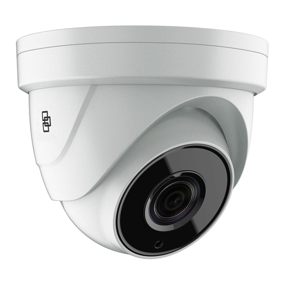
Page 5: Camera Description
Camera description Dome liner TVI video output cable (grey) Bubble Back box Lens DIP switch Power cable Menu button CVBS video output cable (black) Installation Guide... - Page 6 DIP switch to select the camera video output. For TVD-2404/TVD-4404, the built-in DIP switch is used to enable/disable WDR feature, when WDR feature is enabled, the CVBS output will be blocked out.
-
Page 7: Installation
DIP switch Installation To install the camera on a ceiling: Using the template, place it level against the mounting surface and mark the position of the mounting holes. Installation Guide... - Page 8 Following all local codes, drill and prepare the mounting holes. Remove the camera from its back box. Loosen the three set of screws on the edge of the bubble with the supplied hex wrench. Remove the bubble and the dome liner. Secure the back box to the ceiling with the supplied screws.
- Page 9 Note: Please remove the rubber knockout for cable routing outside of the camera, when required. Using a 75-ohm coaxial video cable, connect the camera TVI video output and a TVI DVR, and connect a 12 VDC or 24 VAC power supply to the power cable.
- Page 10 Adjust the surveillance angle: View the camera image on a monitor. Rotate the panning table to adjust the pan direction [0 to 355°]. Loosen the tilting lock screw. Rotate the tilting table to adjust the tilt direction [0 to 90°]. Tighten the tilting lock screw.
- Page 11 Zoom and focus adjustment. View the camera image using the monitor. Loosen the zoom lever and move the screw between T (Tele) and W (Wide) to obtain the appropriate angle of view. Tighten the zoom lock screw. Loosen the focus lever and move the screw between F (Far) and N (Near) to obtain the optimum focus.
-
Page 12: Programming
Zoom Focus Programming Programming on TVI output: Once the camera hardware has been installed, you can configure the camera settings on the TVI DVR. Installation Guide... - Page 13 Please select PTZ protocol as TruVision Coax and click menu button to call up the camera menu. For more details, please see the TVI DVR user manual. Programming on CVBS output: Programming on CVBS output, you need to connect a monitor and a TVS-C200 controller (purchase separately) as following system figure.
- Page 14 In such case, its TVI will be blocked out until you finish the settings and change DIP switch back to TVI. TVD-2404/TVD-4404 The camera has the CVBS and TVI dual video output. The built-in DIP switch is for WDR/CVBS selection.
-
Page 15: Menu
Menu TVD-2402/TVD-4402: Installation Guide... - Page 16 TVD-2404/TVD-4404: Installation Guide...
-
Page 17: Specifications
Specifications Power supply 24 VAC/12 VDC Current TVD-2402/ TVD-4402: 12 VDC: Max. 300 mA 24 VAC: Max. 210 mA TVD-2404/TVD-4404: 12 VDC: Max. 375 mA 24 VAC: Max. 270 mA TVD-2402/ TVD-4402: Power consumption 12 VDC: Max. 3.5W 24 VAC: Max. 5W TVD-2404/TVD-4404: 12V DC: Max. -
Page 18: Legal And Regulatory Information
Legal and Regulatory information Copyright: © 2015 United Technologies Corporation, Interlogix is part of UTC Building & Industrial Systems, a unit of United Technologies Corporation. All rights reserved. Trademarks and patents: Trade names used in this document may be trademarks or registered trademarks of the manufacturers or vendors of the respective products. -
Page 19: Contact Information
For proper recycling, return this product to your local supplier upon the purchase of equivalent new equipment, or dispose of it at designated collection points. For more information see: www.recyclethis.info. Contact information: For contact information, see www.interlogix.com or www.utcfssecurityproducts.eu Installation Guide...
Need help?
Do you have a question about the TVD-2404 and is the answer not in the manual?
Questions and answers