Table of Contents
Advertisement
Quick Links
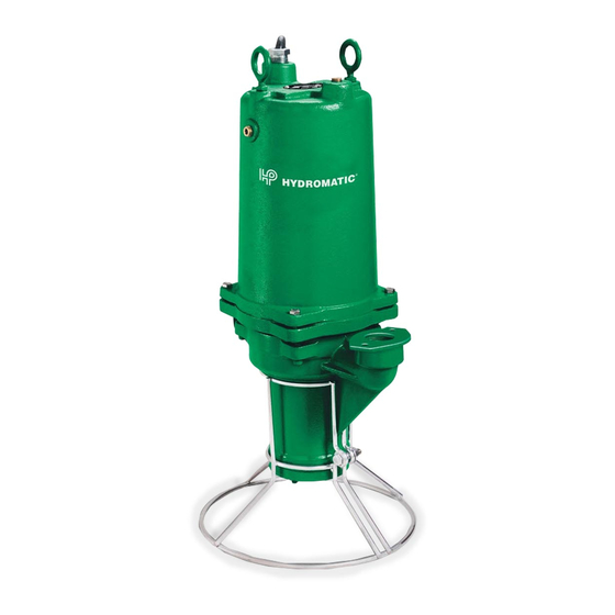
HPD200 – 60 Hz
HPDY200 – 50 Hz
Submersible
Positive Displacement
Grinder Pump
NOTE! To the installer: Please make sure you provide
this manual to the owner of the pumping equipment or to
the responsible party who maintains the system.
Part # 5625-428-1
Pump Installation and Service Manual
Item # E-03-428 03/09
Advertisement
Table of Contents

Subscribe to Our Youtube Channel
Related Manuals for Hydromatic HPD200


Summary of Contents for Hydromatic HPD200
- Page 1 Pump Installation and Service Manual HPD200 – 60 Hz HPDY200 – 50 Hz Submersible Positive Displacement Grinder Pump NOTE! To the installer: Please make sure you provide this manual to the owner of the pumping equipment or to the responsible party who maintains the system.
-
Page 2: General Information
Always disconnect the pump and 1. CAUTION – To reduce risk of Thank you for purchasing your controls from its power source electrical shock, pull plug Hydromatic pump. To help ® before handling or making any before servicing this pump. -
Page 3: Pump Installation
Pump Description: damage must originate at the walls of basin. In either case, be The Hydromatic pumps covered receiving end. Claims for shipping sure that the Hydromatic non-clog these instructions damage cannot be processed at check valve is used and that submersible grinder pumps. -
Page 4: Pump Operations
(See Chart) If not within it counterclockwise while guidelines, return pump to WARNING: Severe injury may holding end of common shaft authorized Hydromatic service result from accidental contact with a screwdriver in slot at or repair center. with moving cutter. - Page 5 5. Clean all parts thoroughly and “Replacing Cutter Parts” 9. Reassemble the pump rotor, before proceeding with sections of this manual. cutter and volute as outlined reassembly. Slide new rotor in the replacing cutter parts 3. Remove the pump rotor per (22) on common shaft and section of this manual.
- Page 6 Pump overloads motor corrected as outlined above, Pump is noisy 1. Specific gravity or viscosity contact your nearest factory of liquid too high 1. Defective bearings representative. 2. Speed too high 2. No diametral clearance HPD200 PERFORMANCE CURVE...
-
Page 7: Winding Resistance Chart
00077-011-1 O-Ring 25338B001 Power Cord 21584B000K Cutter – Stationary, Assy 04580-001-1 Screw – Drive 14570-100-1 Motor (60 Hz – HPD200) 19099A012 Screw – Cap 00589-002-1 Bolt – Eye 14570-101-1 Motor (50 Hz – HPDY200) 00180-002-1 Pin – Roll, Lower 14596-000-1... - Page 8 Pump Notes ______________________________________________ ______________________________________________ ______________________________________________ ______________________________________________ ______________________________________________ ______________________________________________ ______________________________________________ ______________________________________________ ______________________________________________ ______________________________________________ ______________________________________________ ______________________________________________ ______________________________________________ ______________________________________________ ______________________________________________ ______________________________________________ ______________________________________________ ______________________________________________ ______________________________________________ ______________________________________________ ______________________________________________ ______________________________________________ ______________________________________________ ______________________________________________...
- Page 9 Pump Notes ______________________________________________ ______________________________________________ ______________________________________________ ______________________________________________ ______________________________________________ ______________________________________________ ______________________________________________ ______________________________________________ ______________________________________________ ______________________________________________ ______________________________________________ ______________________________________________ ______________________________________________ ______________________________________________ ______________________________________________ ______________________________________________ ______________________________________________ ______________________________________________ ______________________________________________ ______________________________________________ ______________________________________________ ______________________________________________ ______________________________________________ ______________________________________________...
-
Page 10: Limited Product Warranty
If a seal failure should occur, HYDROMATIC will only cover the lower seal and labor thereof. If the heat sensor and seal fail sensor is not attached and functional, the warranty is void. -
Page 12: Start-Up Report
Acknowledge that all information is accurate and proper procedures have been followed: Customer Signature:__________________________________________________ Date ___________ Start-up Technician:__________________________________________________ Date __________ Send to: Warranty Department, 740 E. Ninth Street, Ashland, OH 44805, Fax: 419-207-3344, or e-mail to: startupreport@hydromatic.com We will make this a permanent part of our file on this order.
Need help?
Do you have a question about the HPD200 and is the answer not in the manual?
Questions and answers