Table of Contents
Advertisement
Advertisement
Table of Contents

Related Manuals for Pro-face GP-4311HT


Summary of Contents for Pro-face GP-4311HT
- Page 1 GP4000H Series Installation Guide NHA87487_02_EN...
-
Page 2: Table Of Contents
Please read the “Warning/Caution Information” on the attached sheet before using the product. Safety Information Important Information..................5 Model Numbers Model Numbers....................7 Global Code ....................7 Overview Package Contents..................8 About the Manual...................8 Part Numbers and Functions Part Numbers and Functions .................9 LED Indications....................11 Specifications Electrical Specifications .................12 Environmental Specifications.................12... -
Page 4: Safety Information
Safety Information Important Information Notice Read these instructions carefully, and look at the equipment to become familiar with the device before trying to install, operate, or maintain it. The following special messages may appear throughout this documentation or on the equipment to warn of potential hazards or to call attention to information that clarifies or simplifies a procedure. - Page 5 Safety Information PLEASE NOTE Electrical equipment should be installed, operated, serviced, and maintained only by qualified personnel. No responsibility is assumed by Schneider Electric or any of its affiliates or subsidiaries (hereinafter, referred to as Schneider Electric) for any consequences arising out of the use of this material. A qualified person is one who has skills and knowledge related to the construction and operation of electrical equipment and its installation, and has received safety training to recognize and avoid the hazards involved.
-
Page 6: Model Numbers
*1 Includes models with additional alphanumeric characters at the end of the model number. Global Code A global code is assigned to every Pro-face product as a universal model number. For more information on product models and their matching global codes, please refer to the following URL. -
Page 7: Overview
In addition to this guide, for the detailed information on this product, refer to the GP4000H Series Hardware Manual. You can download the manual from our website at http://www.pro-face.com/trans/en/manual/1001.html. NOTE: The original document is in English, the documents in the other languages are translations from the English. -
Page 8: Part Numbers And Functions
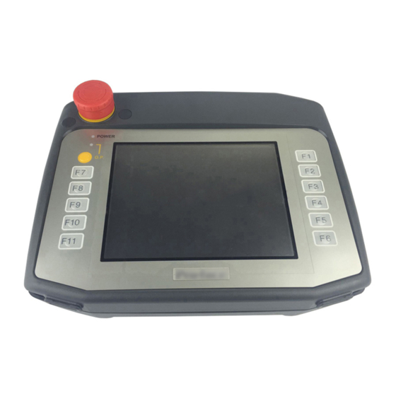
Part Numbers and Functions Part Numbers and Functions Front view Top view Side view Rear view A: Emergency stop switch / stop switch (see page 16) B: Status LED (POWER) (see page 11) C: Operation LED (O.P.) (see page 11) D: Operation switch When the operation switch function is enabled in the screen editing software, accepts inputs from the touch panel or function keys only while... - Page 9 Part Numbers and Functions E: Function switches Use your screen editing software to set up operations associated with switches. For details, refer to the manual of your screen editing software. F: Maintenance cover G: Key switch (see page 16) H: USB (Type A) interface SD card slot J: USB (mini-B) interface K: 3-position enable switch (see page 16)
-
Page 10: Led Indications
Part Numbers and Functions LED Indications Status LED Color Indicator HMI operation Logic program operation Green Offline – In operation Flashing In operation STOP Backlight OFF (Standby Mode) LED fade Orange Flashing Software starting up. Power is turned ON. Flashing In operation Major error –... -
Page 11: Specifications
Specifications Electrical Specifications Rated input voltage 24 Vdc Input voltage limits 19.2...28.8 Vdc Voltage drop 10 ms or less Maximum power 12 W or less consumption When power is not supplied to external devices 8 W or less In-rush current 35 A or less 500 Vac, 20 mA for 1 minute Voltage endurance... -
Page 12: Interface
Specifications Interface Interface for direct-connect cable Description Signal name Key switch output b-contact KEY_NC a-contact KEY_NO 3-position enable a-contact ENB0A switch output a-contact ENB0B a-contact ENB1A a-contact ENB1B Emergency stop switch a-contact EMG0A / stop switch output a-contact EMG0B b-contact EMG1A b-contact EMG1B... -
Page 13: Connection
Connection Connection with Peripheral Equipment A direct-connect cable (sold separately) is required to connect to external devices for communication, power, or wiring of switches. A conversion adapter (model number: AGP3000H-ADPCOM-01) is required to build a system with an external output interface, such as DOUT. NOTE: •... - Page 14 Connection DANGER HAZARD OF ELECTRIC SHOCK, EXPLOSION OR ARC FLASH • Remove all power from the device before removing any covers or elements of the system, and prior to installing or removing any accessories, hardware, or cables. • Unplug the power cable from both this product and the power supply. •...
-
Page 15: Switch
Connection Switch Emergency Stop Switch / Stop Switch With this product incorporating an emergency stop switch or a stop switch, the switch activates the contact output, when the switch is enabled. To reset the stop status (lock status), pull the button forward, or turn the button in the direction indicated by the arrow. -
Page 16: Attaching The Cable
Connection Attaching the Cable Connect the direct-connect cable to this product. Step Action Before connection, remove the cable's connector cap and this product’s connector cover. To remove the cable's connector cap, pull out the cable by holding the cable connector. 1 Cable’s connector cap 2 Cable connector NOTE: To disconnect this cable from the connector cap, be sure to hold the... -
Page 17: Removing The Cable
Connection Turn the cable connector lock ring to lock the connector, so that the small arrow (for LOCK) on the lock ring is aligned with the small arrow on the cable connector. 1 Lock ring 2 Small arrows Removing the Cable Step Action Turn the lock ring so that the small arrow on the lock ring is... -
Page 18: Installation
Installation Installation CAUTION EQUIPMENT DAMAGE • Use this product attached properly to a hand strap, neck strap (sold separately), or a wall hanging adapter (sold separately). • Do not operate or wire this product while it is hung on the wall with the Hanger, attached to the rear. -
Page 19: Attaching The Stop Switch Guard
Installation Attaching the Stop Switch Guard NOTE: When the stop switch guard is attached, the emergency stop switch or the stop switch is not conformable to safety standards (EC Machinery Directive IEC60204-1, etc.). If conforming to the safety standards is required, do not use the stop switch guard (included in this product). -
Page 20: Maintenance
Maintenance Cleaning this product NOTICE EQUIPMENT DAMAGE • Power off this product before cleaning it. • Do not use hard or pointed objects to operate the touch panel as you may damage the panel surface. • Do not use paint thinner, organic solvents, or a strong acid compound to clean the unit. -
Page 21: Standards Standards
Standards For information on certifications and standards, such as certified models and certificates, see the product markings or the following URL: http://www.pro-face.com/trans/en/manual/1002.html Inquiry Do you have any questions about difficulties with your unit? Please access our site any time that you need help with a solution.
Need help?
Do you have a question about the GP-4311HT and is the answer not in the manual?
Questions and answers