Table of Contents
Advertisement
Quick Links
Essential Safety Precautions
System Design
• Do not create GP touch panel switches that could possibly endanger the safety of equipment
and personnel. Damage to the GP, its I/O unit(s), cable(s), and other related equipment can
cause an output signal to remain continuously ON or OFF and possibly cause a major acci-
dent. Therefore, design all monitoring circuits using limit switches, etc. to detect incorrect
device movement. To prevent accidents related to incorrect signal output or operation, design
all switches used to control vital machine operations so they are operated via a separate
control system.
• Do not create switches used to control machine safety operations, such as an emergency stop
switch, as a GP touch screen icon. Be sure to install these switches as separate hardware
switches, otherwise severe bodily injury or equipment damage can occur.
• Please design your system so that equipment will not malfunction due to a communication
fault between the GP and its host controller. This is to prevent any possibility of bodily injury
or material damage.
• Do not use the GP unit as a warning device for critical alarms that can cause serious operator
injury, machine damage or production stoppage. Critical alarm indicators and their control/
activator units must be designed using stand-alone hardware and/or mechanical interlocks.
• The GP is not appropriate for use with aircraft control devices, aerospace equipment, central
trunk data transmission (communication) devices, nuclear power control devices, or medical
life support equipment, due to these devices' inherent requirements of extremely high levels
of safety and reliability.
• When using the GP with transportation vehicles (trains, cars and ships), disaster and crime
prevention devices, various types of safety equipment, non-life support related medical
devices, etc. redundant and/or failsafe system designs should be used to ensure the proper
degree of reliability and safety.
• After the GP's backlight burns out, unlike the GP's "Standby Mode", the touch panel is still
active. If the operator fails to notice that the backlight is burned out and touches the panel, a
potentially dangerous machine miss-operation can occur. Therefore, do not use GP touch
switches for the control of any equipment safety mechanisms, such as Emergency Stop
switches, etc. that protect humans and equipment from injury and damage. If your GP's
backlight suddenly turns OFF, use the following steps to determine if the backlight is actu-
ally burned out.
1) If your GP is not set to "Standby Mode" and the screen has gone blank, your backlight is
burned out.
2) Or, if your GP is set to "Standby Mode", but touching the screen does not cause the
display to reappear, your backlight is burned out.
Also, to prevent accidental machine miss-operation, Digital suggests you use the GP's built-
in "USE TOUCH PANEL AFTER BACKLIGHT BURNOUT" feature, that will automati-
cally detect a burnout and disable the touch screen.
Installation
• High voltage runs through the GP. Except for replacing the backlight, never disassemble the
GP, otherwise an electric shock can occur.
• Do not modify the GP unit. Doing so may cause a fire or an electric shock.
• Do not use the GP in an environment where flammable gasses are present, since operating
the GP may cause an explosion.
Wiring
• To prevent an electric shock, be sure to confirm that the GP's power cord is not connected to
the main power when connecting any cords, cables or lines to the GP.
• Be sure to replace the GP's plastic terminal block cover after wiring is completed, since
operating the GP without the cover may lead to an electric shock
• Do not use power beyond the GP's specified voltage range. Doing so may cause a fire or an
electric shock.
Maintenance
• The GP uses a lithium battery for backing up its internal clock data. If the battery is incor-
rectly replaced, the battery may explode. To prevent this, please do not replace the battery
yourself. When the battery needs to be replaced, please contact your local GP distributor.
WARNINGS
Advertisement
Table of Contents

Related Manuals for Pro-face GP2500-TC11 Series


Summary of Contents for Pro-face GP2500-TC11 Series
- Page 1 Essential Safety Precautions WARNINGS System Design • Do not create GP touch panel switches that could possibly endanger the safety of equipment and personnel. Damage to the GP, its I/O unit(s), cable(s), and other related equipment can cause an output signal to remain continuously ON or OFF and possibly cause a major acci- dent.
- Page 2 CAUTIONS Installation • Be sure to securely connect all cable connectors to the GP. A loose connection may cause incorrect input or output. Wiring • Ground the GP's FG line separately from other units’ FG lines. Putting these FG lines too close may cause an electric shock or unit malfunction.
-
Page 3: Ul/C-Ul(Csa) Approval
UL/c-UL(CSA) Approval The GP2500-TC11 and the GP2600-TC11 are UL/c-UL(CSA) recognized components. (UL file No. E231702) This Unit conforms as a component to the following standards: UL1604 Electrical Equipment for Use in Class I and II Division 2 and Class III Hazard- ous (Classified) Locations UL60950 Safety Standard for Information Technology Equipment (3rd Edition, issued... -
Page 4: Revision Version
CE Marking The GP2500-TC11 and GP2600-TC11 are CE marked products that con- form to EMC directives and the Low-voltage directive. These units also con- form to EN55011 ClassA, EN61000-3-2, EN-61000-3-3, EN61000-6-2, EN60950 directives. For detailed CE marking information, please contact your local distributor. <Cautions>... -
Page 5: Package Contents
Package Contents The following items are included in the GP's package. Before using the GP, please confirm that all items listed here are present. GP Unit (1) Installation Guide (1) (GP2500-TC11/ <This Guide> GP2600-TC11) Installation Gasket (1, attached to the GP unit) Installation Fasteners (4/set) Screw Lock Terminal Block (1, attached to the GP unit) -
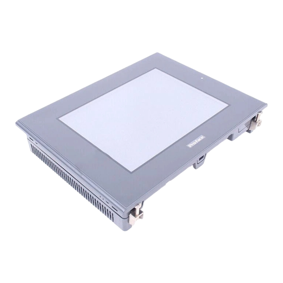
Page 6: Part Names
Part Names A : Display B : Touch Panel C : Status LED GP Status Not Lit Power is OFF. Green Normal operation Backlight is not functioning. Orange (Refer to 10.Replacing the Backlight. ) D : Power Input Terminal Block E : Expansion Unit Interface 1 F : Expansion Unit Interface 2 G : CF Card Expansion Interface... -
Page 7: Dip Switches
Dip Switches These switches are located inside the CF Card's cover. The factory settings for these switches are OFF. Dip Switches Rear View of GP Dip Switch Function Note This Dip switch Startup from Startup from CF Card with setting controls CF Card is CF Card is startup data... - Page 8 Interfaces Serial Interface (HOST-I/F) This interface is used to connect the GP to the host (PLC), via an RS-232C or RS- 422 cable. Signal Pin Arrangement Pin # Description Name Frame Ground Send Data (RS-232C) Receive Data (RS-232C) Request to Send (RS-232C) Clear to Send (RS-232C) Data Set Ready (RS-232C) Signal Ground...
- Page 9 When creating a cable, please be aware of the following: <For RS-422 Connectors> • The following pairs of pin no.s must be connected (shorted)..#18 (CSB) <-> #19 (ERB) ...#21 (CSA) <-> #22 (ERA) • Connecting the #9 (TRMX) and #10 (RDA) wires, adds a termination resistance of 100Ω...
-
Page 10: Installation
Screw Lock Terminal Block (12 pin) This interface performs external reset, alarm output, buzzer output and sound output. Pin Arrangement Pin No. Signal Name Description External Reset AUXCOM External Reset Common AUXRESET External Reset Input Online ALARM System Alarm Output OUTCP 24VDC BUZZ... - Page 11 Create a Panel Cut and insert the GP into the panel from the front Unit: mm [in] Panel +0.04 301.5 [11.87 Attach the Installation Fasteners from Inside the Panel The following figures show the four(4) fastener insertion slot locations. Insert each fastener's hook into the slot and tighten it with a screwdriver.
- Page 12 • To avoid a short caused by loose ring terminals, be sure to use ring terminals with an insulating sleeve. • When the FG terminal is connected, be sure the wire is grounded. Not grounding the GP unit will result in excess noise and vibra- tion.
-
Page 13: Power Supply Cautions
*1 Use a grounding resistance of 100 Ω , a wire of 2mm thicker, or your country's applicable standard. *2 For GP-2600 Series, the backlight differs depending on a Rev. For the correct backlight and how to distinguish Rev., refer to the User Manual carried in the Pro-face Web Site (http://www.pro-face.com/).
Need help?
Do you have a question about the GP2500-TC11 Series and is the answer not in the manual?
Questions and answers