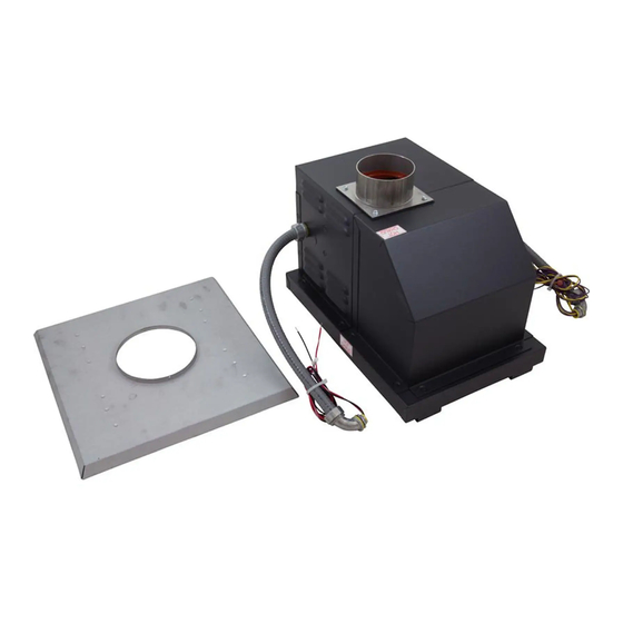
Raypak D-2 POWER VENT 206A Installation & Operating Instructions Manual
For 206a, 207a, 266a; 267a; 336a; 406a 407a swimming pool & spa heaters
Hide thumbs
Also See for D-2 POWER VENT 206A:
- Installation & operating instructions manual (60 pages) ,
- Installation and operation manual (52 pages) ,
- Replacement instructions manual (18 pages)
Advertisement
INSTALLATION & OPERATING
INSTRUCTIONS
206A, 207A, 266A, 267A, 336A, 337A, 406A, 407A
(ELECTRONIC IGNITION MODELS ONLY)
WARNING: If these instructions are not followed exactly, a fire or explosion may result
causing property damage, personal injury or death.
Do not store or use gasoline or other flammable vapors and liquids in the vicinity
of this or any other appliance.
• Do not try to light any appliance.
WHAT TO DO IF YOU SMELL GAS:
• Do not touch any electrical switch; do not use any phone in your building.
• Immediately call your gas supplier from a neighbor's phone. Follow the gas
supplier's instructions.
• If you cannot reach your gas supplier, call the fire department.
Installation and service must be performed by a qualified installer, service agency
or the gas supplier.
D-2 POWER VENT
Advertisement
Table of Contents

Subscribe to Our Youtube Channel
Summary of Contents for Raypak D-2 POWER VENT 206A
- Page 1 INSTRUCTIONS D-2 POWER VENT 206A, 207A, 266A, 267A, 336A, 337A, 406A, 407A (ELECTRONIC IGNITION MODELS ONLY) WARNING: If these instructions are not followed exactly, a fire or explosion may result causing property damage, personal injury or death. Do not store or use gasoline or other flammable vapors and liquids in the vicinity of this or any other appliance.
- Page 2 Rev. 3 Changes to:...
-
Page 3: Receiving Equipment
RECEIVING EQUIPMENT GENERAL SPECIFICATIONS HEATER FACTORY- D-2 POWER VENT MODELS WIRED PART NO. -
Page 4: Installation Requirements
DIMENSIONS 18.13 7.91 13.59 DIMENSIONAL DATA Model 1.88 4.38 INSTALLATION REQUIREMENTS... -
Page 5: Installation
INSTALLATION... - Page 6 INSTALLATION (Continued)
- Page 7 INSTALLATION (Continued)
- Page 8 INSTALLATION (Continued) VENTING...
- Page 9 Minimum Clearances from Vent/Air Inlet Terminations—Indoor and Outdoor Installations Clearance above grade, veranda, porch, deck, or balcony Clearance to window or door that may be opened Clearance to permanently closed window Vertical clearance to ventilated soffit located above the terminal within a horizontal dis- tance of 2 ft (61cm) from the centerline of the terminal Clearance to unventilated soffit...
- Page 10 VENTING (Continued)
- Page 11 VENTING (Continued)
- Page 12 VENTING (Continued)
- Page 13 VENTING (Continued)
-
Page 14: Sequence Of Operation
SEQUENCE OF OPERATION DRAFT-PROVING SWITCH WIRING Y/BK Y/BK V/BK GAS VALVE RELAY Y/BK V/BK V/BK PRESSURE SWITCH... - Page 15 WIRING (Continued) MODELS 207, 267, 337, 407 EQUIPPED WITH HONEYWELL GAS VALVE STEP 1 : VERIFY CURRENT CONNECTIONS AS SHOWN BELOW. RELAY R/BK P/PV Y/BK HONEYWELL M/MV VALVE V/BK STEP 2 : DISCONNECT BOTH TERMINALS MVPV & MV AS SHOWN BELOW. RELAY GROUND ON VALVE...
- Page 16 WIRING (Continued) MODELS 206, 266, 336, 406 EQUIPPED WITH HONEYWELL GAS VALVE STEP 1 : VERIFY CURRENT CONNECTIONS AS SHOWN BELOW. R/BK P/PV Y/BK HONEYWELL M/MV VALVE V/BK STEP 2 : DISCONNECT BOTH TERMINALS MVPV & MV FROM VALVE AS SHOWN BELOW. R/BK P/PV HONEYWELL...
- Page 17 WIRING DIAGRAM – MODELS 207A, 267A, 337A, 407A...
- Page 18 WIRING DIAGRAM – MODELS 206A, 266A, 336A, 406A...
-
Page 19: Replacement Parts
REPLACEMENT PARTS NOTE: ILLUSTRATED PARTS LIST Call Out Description DPDT Relay N.O. Air Pressure Switch 4"-90° Elbow w/Screen Combustion Flue Box Base Assembly Flue Collar Flue Adapter 4" Flange Blower Adapter Control Cover Control Swaybrace Silicone Hose Front Panel Blower Cooling Fan MANUFACTURER: 206/207 266/267... - Page 20 www.raypak.com...


Need help?
Do you have a question about the D-2 POWER VENT 206A and is the answer not in the manual?
Questions and answers