Raypak 266A Installation And Operation Manual
Gas-fired pool and spa heater
Hide thumbs
Also See for 266A:
- Installation & operating instructions manual (60 pages) ,
- Installation and operation manual (52 pages) ,
- Replacement instructions manual (18 pages)
Table of Contents
Advertisement
INSTALLATION AND
OPERATION MANUAL
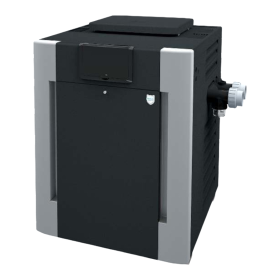
Gas-Fired Pool
and Spa Heater
Bronze ASME and Polymer
Atmospheric Heat Exchanger Models
206A, 266, 266A, 336A, 399, and 406A
WARNING: If the information in the instructions is not followed exactly, a fire or explosion may result
A
causing property damage, personal injury or death.
- Do not store or use gasoline or other flammable vapors and liquids or other combustible materials in
the vicinity of this or any other appliance. To do so may result in an explosion or fire.
- WHAT TO DO IF YOU SMELL GAS
• Do not try to light any appliance.
• Do not touch any electrical switch; do not use any phone in your building.
• Immediately call your gas supplier from a neighbor's phone. Follow the gas supplier's instructions.
• If you cannot reach your gas supplier, call the fire department.
- Installation and service must be performed by a qualified installer, service agency or the gas supplier.
This manual should be maintained in legible condition and kept adjacent to the heater or in a safe place for future
reference.
A
S
M
E
HLW
BR models only
Effective: 10-24-20
Replaces: 08-21-20
P/N 241236 Rev. 39
Advertisement
Table of Contents


Need help?
Do you have a question about the 266A and is the answer not in the manual?
Questions and answers
the heater starts working bud in 10 seconds the gas valve shut off and on the display show Fan. this heater doesn't have a fan
The Raypak heater model 266A could shut off the gas valve and display "Fan" due to a misinterpretation or error on the control board. This might occur if the heater is connected to an automated control system that is sending incorrect mode signals, or if there is a wiring or board malfunction. Checking the diagnostic LEDs and using the fault guide on the control module can help identify the exact cause.
This answer is automatically generated