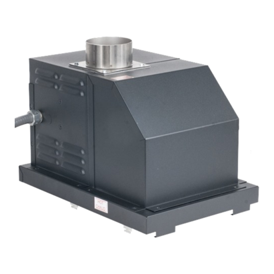
Raypak Power Vent D2 Installation & Operating Instructions Manual
For 181/182, 260/261, 330/331 & 400/401 – boilers & water heaters
Hide thumbs
Also See for Power Vent D2:
- Installation & operating instructions manual (20 pages) ,
- Operating and installation instructions (14 pages) ,
- Specifications (2 pages)
Table of Contents
Advertisement
Quick Links
If these instructions are not followed exactly, a fire or explosion may
result causing property damage, personal injury or death
liquids or other combustible materials in the vicinity of this or any other appliance. To
do so may result in an explosion or fire.
• Do not try to light any appliance.
• Do not touch any electrical switch; do not use any phone in your building.
• Immediately call your gas supplier from a neighbor's phone. Follow the gas
supplier's instructions.
• If you cannot reach your gas supplier, call the fire department.
Installation and service must be performed by a qualified installer, service agency or
the gas supplier.
This manual should be maintained in legible condition and kept adjacent to the heater or in another safe place for
future reference.
CATALOG NO. 6000.57F
Do not store or use gasoline or other flammable vapors and
Effective: 12-02-08
.
Replaces: 5-20-08
P/N 241086 Rev. 7
Advertisement
Table of Contents

Summary of Contents for Raypak Power Vent D2
- Page 1 If these instructions are not followed exactly, a fire or explosion may result causing property damage, personal injury or death Do not store or use gasoline or other flammable vapors and liquids or other combustible materials in the vicinity of this or any other appliance. To do so may result in an explosion or fire.
- Page 2 Rev. 7 reflects the following: Changes to: The text in paragraph one of the Venting section on page 8.
- Page 3 Pay Attention to These Terms 182-260 H4/WH1 (Atmospheric) 181-261 H4/WH1 (Low NOx)
- Page 4 Indicates the presence of immediate hazards which will cause severe personal injury, death or substantial property damage if ignored. Indicates the presence of hazards or unsafe practices which could cause severe personal injury, death or substantial property damage if ignored. Indicates the presence of hazards or unsafe practices which could cause minor personal injury or product or property damage if ignored.
- Page 5 Z21.13 for boilers. The Power Vent Assembly is a fan assisted combus- tion system designed for application to Raypak Heater Models 181-401. The unit, when installed as directed, is capable of operating in applications such as through the wall venting and reduced horizontal and vertical vent pipe sizes in new and existing installations.
- Page 6 7. Mount the Power Vent on the outer top. 8. Route the conduit harness of the Power Vent thru the outer top hole, around the adapter towards the back of the unit. Continue routing the harness thru the corner slot, which leads to open area behind the access panel.
- Page 7 Fig. 3: Minimum Clearances from Vent/Air Inlet Terminations – Indoor and Outdoor Installations Clearance above grade, veranda, porch, deck, or balcony Clearance to window or door that may be opened Clearance to permanently closed window Vertical clearance to ventilated soffit located above the terminal within a horizontal dis- tance of 2 ft (61cm) from the centerline of the terminal...
- Page 8 DIAMETER LEFT SIDE Fig. 4: Draft Assembly The Raypak Power Vent operates with a positive vent static pressure and with a vent gas temperature that avoids excessive condensate production in the vent and as such it is listed as a CATEGORY III appliance.
- Page 9 The D-2 Power Vent assembly includes a wire harness, shown in Fig. 6 below, which provides quick connec- tions with the respective controls in the heater control box. The harness is of sufficient length to fit the appliance for which it is sized. Reference the wiring diagram supplied with each appliance for actual connections.
- Page 12 Model Dimensional Data 18.13 12.38 18.13 12.38 7.88 4.25 18.13 12.38 18.13 12.38 7.88 18.13 12.38 18.13 12.38 18.13 12.38 7.88 17.50 15.75 18.13 12.38 7.88 17.50 15.75 17.50 15.75 17.50 15.75 7.63 17.50 15.75 17.50 15.75 7.63 Table D: Dimensional Data 17.50 15.75 7.63 17.50 15.75 7.63 7.88...
- Page 13 On call for heat, the D-2 Power Vent fan (and appli- ance pump) start. When the flow switch circuits close, the ignition system consisting of an electronic spark module, pilot gas system and flame sensor, are ener- gized. When draft proving switch closes and all safety circuits are proven, the automatic main gas valves will open and the heater will operate.
- Page 14 Call Out Description Power Vent Relay Power Vent Blower Power Vent NO Pressure Switch Elbow 4"-90° with Screen Power Vent Flue Box Power Vent Base Assembly Power Vent Flue Collar Power Vent Flue Adaptor Power Vent 4" Flange Power Vent Blower Adaptor Power Vent Control Cover Power Vent Control Swaybrace Power Vent Silicone Hose...
- Page 16 Raypak, Inc., 2151 Eastman Avenue, Oxnard, CA 93030 (805) 278-5300 Fax (805) 278-5468 Litho in U.S.A.


Need help?
Do you have a question about the Power Vent D2 and is the answer not in the manual?
Questions and answers