Sign In
Upload
Manuals
Brands
York Manuals
Air Handlers
AHU
York AHU Manuals
Manuals and User Guides for York AHU. We have
1
York AHU manual available for free PDF download: Operation And Maintenance
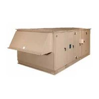
York AHU Operation And Maintenance (118 pages)
AIR HANDLING UNITS
Brand:
York
| Category:
Air Handlers
| Size: 5.39 MB
Table of Contents
Table of Contents
5
Section 1 - General Information and Safety
13
Introduction
13
About this Manual
13
Warranty
13
Responsibility for Safety
13
Section 2 - Start-Up and Operation
15
Before Start-Up
15
FIGURE 1 - Solution XT Seismic Isolator
15
FIGURE 2 - Example of a Solution XT Termination Chart
16
Inspecting Fan Assembly
16
TABLE 1 - Torque for Tightening Set Screws
16
Checking Isolators
17
FIGURE 3 - Fan and Motor Isolator Support Frame
17
FIGURE 4 - Spring Isolator
17
Inspecting Belts and Sheaves
17
FIGURE 5 - Spring Isolator Set-Up
18
Checking Operation of Dampers
19
Checking Operation of Fans
19
FIGURE 6 - Counterbalance Locked into Place for Shipping
19
FIGURE 7 - Counterbalance Unlocked for Start-Up
19
Start-Up
19
FIGURE 10 - Front of a 1X2 Fan Array
20
FIGURE 8 - Front of a 2X2 Fan Array
20
FIGURE 9 - Back of a 2X2 Fan Array
20
TABLE 2 - Air Measuring Device Connections
21
FIGURE 11 - High and Low Connections for an in Fan Air Monitoring System
23
FIGURE 12 - High and Low Connections and Associated Tubing for Fan Mounted Air Monitoring System
24
FIGURE 13 - Port Locations for Fan Mounted Air Monitoring System
24
FIGURE 14 - Ductwork Inlet Requirements
25
FIGURE 15 - Ductwork Radius
25
FIGURE 16 - 25% Sensing Option
25
FIGURE 17 - 25%/75% Sensing Option
25
FIGURE 18 - 25%/75% Sensing Option
26
TABLE 3 - Indoor Unit Example
27
Energize Fan Motors
28
TABLE 4 - Outdoor Unit Example
28
Check Doors and Latches
29
Energy Recovery Wheel
29
FIGURE 19 - Example of Sweep Balance Results Label on Fan Housing
29
FIGURE 20 - Metal Spacers on Solution XT Doors
29
FIGURE 21 - Vertical Wheel for Indoor AHU
29
Variable Frequency Drive (VFD)
29
FIGURE 22 - Horizontal Wheel for Outdoor AHU
30
FIGURE 23 - Energy Recovery Wheel - Pulley Side
31
FIGURE 24 - Segment Retainer
32
FIGURE 25 - Diameter Seal Adjustment
32
FIGURE 26 - Purge Angle Detail
33
FIGURE 27 - Purge Angle Detail
34
Indirect Fired Gas Heat Start up
34
FIGURE 28 - Gas Furnace Condensate Drain Trap
36
FIGURE 29 - Open Fuse Disconnects
37
FIGURE 30 - Set ID Fan Damper
37
FIGURE 31 - Check Main Gas Supply Pressure
37
FIGURE 32 - Draft over Fire Test Port
38
FIGURE 33 - Flue Combustion Temperature and Efficiency Test Port- ID Blower
38
FIGURE 34 - Damper Actuator
38
TABLE 5 - Gas Heat Segment Model Number Nomenclature
39
TABLE 6 - Natural Gas Pressure Requirements (Inches Wc)
40
TABLE 7 - Natural Gas Pressure Requirements (Inches Wc)
41
TABLE 8 - Inlet Size (NPT)
42
FIGURE 35 - Example Solution XT Gas Furnace Fuel Venting System
43
FIGURE 36 - Typical Wiring Diagram
44
TABLE 9 - Burner Temperature Rise
45
Starting the Electric Heater
46
TABLE 10 - Maximum Current for 75°C Copper Wire
47
FIGURE 37 - Minimum Air Velocity Required for Safe Operation
48
FIGURE 38 - Pressure Probe Direction
49
FIGURE 39 - Air Flow Switch Connections
49
Operation
50
Test and Balance
50
Setting Limits
50
Checking Motors, Belts and Sheaves
51
P-Cone
51
FIGURE 40 - V-Belt Drive Kit Label
51
Section 3 - Maintenance
53
General Requirements
53
TABLE 11 - Minimum / Maintenance Requirements According to ASHRAE
53
Inspect Parts
54
Cabinet
54
Door Hardware and Gaskets
54
Panels
54
Hoods and Louvers
54
Bird Screens
54
Optional Moisture Eliminators
54
Outdoor Air Hood
54
FIGURE 41 - Remove Mist Eliminator
54
FIGURE 42 - Weather Hood Installation
54
Fan Segment (Supply, Return or Exhaust)
55
Removing the Fan
55
Checking the Fan
55
Operating Adjustable Motor Base
55
Standard
55
FIGURE 43 - Typical Drive Kit Data Tag
55
FIGURE 44 - Solution XT Adjustable Motor Base
55
FIGURE 45 - Solution XT Adjustable Motor Base (Top Mount)
56
Checking Belt Tension
57
Aligning Sheaves
57
FIGURE 46 - Belt Tensioning
57
FIGURE 47 - Belt Tensioning Gauge
57
Using a Straightedge
58
Using a String
58
Belt Replacement Tensioning and Sheave Alignment for Top Mount
58
FIGURE 48 - Alignment Using Straight Edge
58
FIGURE 49 - Alignment Using String
58
FIGURE 50 - Sheave Angular Misalignment
59
FIGURE 51 - Motor Base Lowered
59
FIGURE 52 - Sheave Angular Alignment
59
Lubrication
60
FIGURE 53 - Sheave Angular Misalignment
60
FIGURE 54 - Sealed Bearing
60
FIGURE 55 - Bearing with Set Screw Type Locking Device
60
FIGURE 56 - Bearing with Eccentric Cam
60
Fan Bearing Lubrication
61
Checking Condition of Extended Lubrication Lines
61
Recommended Lubricant for Bearings
61
Proper Interval and Quantity
61
FIGURE 57 - Split Bearing (Assembled)
61
FIGURE 58 - Optional Lubrication Lines
61
Lubricating the Fan Segment and Motor
62
TABLE 12 - Fan Bearing Re-Lubrication Intervals for Ball Bearing Pillow Blocks
62
TABLE 13 - Fan Bearing Lubrication Intervals for Spherical Roller Bearing Solid Pillow Blocks
62
TABLE 14 - Fan Bearing Lubrication Intervals for Spherical Roller Bearing Split Pillow Blocks
62
TABLE 15 - Fan Bearing Lubrication Intervals for Dodge ISN Bearings
62
Checking Condition of Mounting Hardware, Adjustable Motor Base and Motor
63
Checking Electrical Connections
63
FIGURE 59 - Open Drip Proof (ODP) Motor
63
FIGURE 60 - Totally Enclosed Fan Cooled (TEFC) Motor
63
Keep Motor Bearing Lubricated
63
UVC Emitter Lamps
64
TABLE 16 - Motor Bearing Lubrication Intervals
64
TABLE 17 - Motor Bearing Service Conditions
64
TABLE 18 - Motor Bearing Lubrication Interval Multiplier
64
Three Types of Lamps
65
Maintaining and Replacing Filter Segments
65
FIGURE 61 - UV Lamps
65
FIGURE 62 - Installing V-Mod Lamp
65
FIGURE 63 - Installing V-Ray and V-Max Grid Lamps
65
FIGURE 64 - V-Max Grid Lamps
65
FIGURE 65 - Typical Filter Types
65
Replacing the Filters
66
Economizer Segment (Dampers)
66
Cleaning Procedure
66
Hardware Check
66
Coil Segment Cleaning
66
Tools, Equipment and Materials
66
FIGURE 66 - Installing Angle Filters
66
FIGURE 67 - Installing Side Load Filters
66
Cleaning Procedure
67
Condensate Drain Pan, Trap and Line Cleaning
67
Tools, Equipment and Materials
67
Schedule and Conditions
67
Cleaning Procedure
68
Coil Freeze Protection
68
Energy Recovery Wheel
68
Airxchange
68
Tools and Materials
68
Cleaning the Wheel
69
Adjusting Air Seals
69
FIGURE 68 - Rinse Segments
69
FIGURE 69 - Diameter Seal Adjustment
69
Inspect Wheel Drive Components
70
Novelaire ® Technologies
70
Cleaning the Wheel
70
FIGURE 70 - Airxchange ® Energy Recovery Wheel with Bearing Support Beam Side
70
Adjusting Air Seals
71
Inspect Wheel Drive Components
71
How to Measure, Assemble and Install
71
FIGURE 71 - How to Measure
71
FIGURE 72 - Disassembly
71
FIGURE 73 - Assembly
71
Thermotech
72
Cleaning the Wheel
72
Adjusting Air Seals
72
FIGURE 74 - Installation
72
FIGURE 75 - Loosen Screws before Adjusting Seals
72
Inspect Wheel Drive Components
73
Innergy Tech
73
Cleaning the Wheel
73
Adjusting Air Seals
73
FIGURE 76 - ERW Seal Locations
73
Inspect Wheel Drive Components
74
FIGURE 77 - Airloop™ Labyrinth Seal Adjustment
74
Econo-Disk
75
Maintenance Instructions
75
P-Cone
75
Maintenance of P-Cone
75
FIGURE 78 - Plenum Fan Tap Location and Connection Illustration
75
FIGURE 79 - Maintenance Requirements
76
Section 4 - Service and Repair
77
Service Tools and Equipment
77
Service Information
78
Troubleshooting
78
Pitot Tube
78
FIGURE 80 - Construction of Pitot Tube
78
FIGURE 81 - Pitot Tube
78
Inclined Manometer
79
Filter Gauge
79
U-Tube Manometer
79
FIGURE 84 - Magnehelic Filter Guage
79
FIGURE 82 - Inclined Manometer
79
FIGURE 83 - Minihelic Filter Gauge
79
Duct Pressures
80
Velocity
80
FIGURE 85 - U-Tube Manometers
80
FIGURE 86 - Slack Tube Manometer
80
Static Pressure
81
Total Pressure
81
Requesting Assistance
81
FIGURE 87 - Static Pressure Air System
81
Adjusting, Removing, and Installing Sheaves
82
Fixed Pitch Sheaves (T.B Woods with Sure Grip Bushings)
82
FIGURE 88 - Inserting Cap Screws
82
FIGURE 89 - Standard Mounting
82
FIGURE 90 - Reverse Mounting
83
TABLE 19 - Cap Screw Torque Values
83
TABLE 20 - Set Screw Torque Values
83
Adjustable Pitch Sheaves (T.B. Woods - Model JVS)
84
FIGURE 91 - Adjustable Pitch Sheave (JVS)
84
Adjustable Pitch Sheaves (T.B. Woods - Model FHP)
85
FIGURE 92 - Adjustable Pitch Sheave (FHP)
85
Controls
86
Section 5 - Wiring Diagrams
87
FIGURE 93 - Full Voltage Starter
88
Controls
89
FIGURE 94 - Full Voltage Starter with Single Point Power Connection (204195)
90
Controls
91
FIGURE 95 - Outside Air Damper Kit (Relay Installation)
92
Installing Kit (if Applicable)
92
FIGURE 96 - Solution XT Termination Chart Inside Enclosure Door
93
FIGURE 97 - Typical FPC Wiring Diagram
94
FIGURE 98 - Transformer Enclosure Wiring Detail (Shown Open)
96
FIGURE 99 - Transformer Wiring Diagram
97
FIGURE 100 - UV Control Panel Wiring (8 Amps)
99
FIGURE 101 - UV Control Panel Wiring ( Greater than 8 Amps)
100
FIGURE 102 - Gas Heat, Single Phase, 1500Va Transformer Wiring Diagram
102
FIGURE 103 - Gas Heat, Three Phase, 1000Va Transformer Wiring Diagram
103
FIGURE 104 - Gas Heat, Three Phase, 500Va Transformer Wiring Diagram
104
FIGURE 105 - Typical Wiring Diagram for Electric Heat Control Type Vermier
105
FIGURE 106 - Typical Wiring Diagram for Control Type Full SCR
106
Appendix A - Start-Up Checklist
107
Appendix B - Long-Term Storage
111
Temperature
116
TABLE 21 - si Metric Conversion
116
Advertisement
Advertisement
Related Products
York AHR22B3XH21
York AHP24B4FH21
York AHP36C4GH21
York AHP42C4HH21
York AHP48D3XH21
York AHP42C2CN21
York AHP42C2CH21
York AHP60D3XN21
York AHP42C3XN21
York AHP36C2AH21
York Categories
Air Conditioner
Heat Pump
Chiller
Furnace
Air Handlers
More York Manuals
Login
Sign In
OR
Sign in with Facebook
Sign in with Google
Upload manual
Upload from disk
Upload from URL