
Related Manuals for York SOLUTION XTI Series


Summary of Contents for York SOLUTION XTI Series
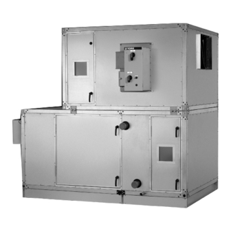
- Page 1 SOLUTION™ AIR HANDLING UNITS INSTALLATION AND ASSEMBLY Supersedes: 102.20-N1 (615) Form 102.20-N1 (716) SOLUTION™ XT INDOOR AND OUTDOOR UNITS LD09624 INDOOR AHU (XTI) LD17323 OUTDOOR AHU (XTO) Issue Date: July 6, 2016...
- Page 2 FORM 102.20-N1 ISSUE DATE: 7/06/2016 IMPORTANT! READ BEFORE PROCEEDING! GENERAL SAFETY GUIDELINES This equipment is a relatively complicated apparatus. which it is situated, as well as severe personal injury or During rigging, installation, operation, maintenance, death to themselves and people at the site. or service, individuals may be exposed to certain com- This document is intended for use by owner-authorized ponents or conditions including, but not limited to:...
- Page 3 If there is any ques- ASSOCIATED LITERATURE MANUAL DESCRIPTION FORM NUMBER York Air Handling Units Operation and Maintenance 102.20-OM1 Steps to Protect New Equipment Warranty 102.20-CL1 Air Handling Units Start-up Checklist 100.00-CL1...
- Page 4 FORM 102.20-N1 ISSUE DATE: 7/06/2016 SOLUTION XT UNIT MODEL NOMENCLATURE 048 x VOLTAGE CODE 12=120-1-60 17=200 or 208-3-60 NOMINAL NOMINAL FACTORY MOUNTED HEIGHT WIDTH 27=277-1-60 END DEVICES 27 to 132 27 to 288 28=230 or 240-3-60 0=No 40=360-3-60 1=Yes 44=440-3-50 ENVIRONMENT 46=460-3-60 I=Indoor...
-
Page 5: Table Of Contents
FORM 102.20-N1 ISSUE DATE: 7/06/2016 TABLE OF CONTENTS SECTION 1 - GENERAL INFORMATION AND SAFETY ..................13 Introduction ..............................13 Warranty ................................. 13 Responsibility for Safety ..........................13 SECTION 2 - PRODUCT DESCRIPTION .......................15 Typical Solution Operation ..........................15 Ventilation System ..........................15 Economizer System (Typical) ........................ - Page 6 FORM 102.20-N1 ISSUE DATE: 7/06/2016 TABLE OF CONTENTS (CONT'D) Setting Up and Pulling Solution XT Sections Together ................. 41 Installing a Tiered AHU ..........................43 Assembling the Solution XT End Channel Shipping Split ..............45 Installing Hood with Moisture Eliminators ....................47 Outdoor Air Temperature and/or Humidity Sensors ................
- Page 7 FORM 102.20-N1 ISSUE DATE: 7/06/2016 TABLE OF CONTENTS (CONT'D) Vertical Tube Integral Face and Bypass (VIFB) and Integral Face and Bypass (IFB) ........79 Shipping Bolts (VIFB Only) ........................79 Piping Suggestions ..........................79 Flexible Connectors (VIFB Only) ......................79 Freezing Conditions ..........................79 Refrigeration ..............................
- Page 8 FORM 102.20-N1 SOLUTION XT UNIT MODEL NOMENCLATURE ISSUE DATE: 7/06/2016 LIST OF FIGURES FIGURE 1 - Cutaway of Solution XT Showing Segmented Construction ..............15 FIGURE 2 - AHU and Coil Hand Identification ......................16 FIGURE 3 - AHU ID Label ............................17 FIGURE 4 - Skid ID Label ............................17 FIGURE 5 - Example of Segment Id Box ........................17 FIGURE 6 - Example of Moisture Eliminator Loose Component ID Label ..............
- Page 9 FORM 102.20-N1 SOLUTION XT UNIT MODEL NOMENCLATURE ISSUE DATE: 7/06/2016 LIST OF FIGURES (CONT'D) FIGURE 46 - Electrical Connectors (Connected) ....................37 FIGURE 47 - Remove and Reposition Shipping Split Angle ................... 37 FIGURE 48 - Come-A-Long Attached to a Section ....................37 FIGURE 49 - Bring Shipping Splits Together ......................
- Page 10 FORM 102.20-N1 SOLUTION XT UNIT MODEL NOMENCLATURE ISSUE DATE: 7/06/2016 LIST OF FIGURES (CONT'D) FIGURE 93 - Position Cover Angle Properly ......................60 FIGURE 94 - Properly Install Screws ........................60 FIGURE 95 - Apply Solution XT Base Rail Cover ....................60 FIGURE 96 - Gas Furnace Fuel Venting System ....................
- Page 11 FORM 102.20-N1 SOLUTION XT UNIT MODEL NOMENCLATURE ISSUE DATE: 7/06/2016 LIST OF FIGURES (CONT'D) FIGURE 140 - Trap Detail for Drain Pan in Positive Environment (Blow Through) ..........90 FIGURE 141 - Combining Drain Lines ........................90 FIGURE 142 - Recommended Discharge Duct Arrangement when Turns are Required ........91 FIGURE 143 - Duct Arrangement for Flange and Raw Edge Ducts ................92 FIGURE 144 - Duct Penetration of Roof .........................93 FIGURE 145 - Roof to Duct Installation (Horizontal Discharge) ................93...
- Page 12 FORM 102.20-N1 SERVICE TASK REFERENCE ISSUE DATE: 7/06/2016 SERVICE TASK REFERENCE Air Filters Installing Hood with Moisture Eliminator Installing a 2 in. Pleated Filter Installing Indoor Solution XT AHU Installing a 4 in. Pleated Filter Installing an Solution XT AHU with Expanded Installing a Single Headered (SH) Filter Cabinet Installing a 2 in.
-
Page 13: Section 1 - General Information And Safety
AHU. lowing conditions must be satisfied: • Contains detailed procedures, including installa- • Only genuine YORK approved spare parts must tion, commissioning and maintenance tasks that be used. must only be performed by suitably trained and • All of the scheduled maintenance operations de-... - Page 14 FORM 102.20-N1 SECTION 1 - GENERAL INFORMATION AND SAFETY ISSUE DATE: 7/06/2016 THIS PAGE INTENTIONALLY LEFT BLANK. JOHNSON CONTROLS...
-
Page 15: Section 2 - Product Description
FORM 102.20-N1 ISSUE DATE: 7/06/2016 SECTION 2 - PRODUCT DESCRIPTION The AHU features segmented construction, and is fac- Ventilation System tory assembled. Segment arrangements will vary to suit The purpose of a ventilation system is to remove air the job application as shown in Figure 1 on page 15. that is substandard to creature comfort or a process, Features of the AHU include: and replace it with suitable air. -
Page 16: Heating And Cooling System
FORM 102.20-N1 SECTION 2 - PRODUCT DESCRIPTION ISSUE DATE: 7/06/2016 Heating and Cooling System HAND ORIENTATION Various types of heating and cooling may be applied, Coil connections and other components are located and which include: described as left or right hand. The proper orientation to describe the proper hand is when airflow is at your • Hot water or steam coils back as shown in Figure 2 on page 16. -
Page 17: Ahu Id Label
FORM 102.20-N1 SECTION 2 - PRODUCT DESCRIPTION ISSUE DATE: 7/06/2016 AHU ID Label Skid ID Label The AHU ID label contains the following information Each skid in a multi-piece AHU is marked with a skid as shown in Figure 3 on page 17: ID label, which indicates its order of assembly in the direction of airflow as shown in Figure 4 on page 17. -
Page 18: Table 1 - Definition Of Segment Ids
FORM 102.20-N1 SECTION 2 - PRODUCT DESCRIPTION ISSUE DATE: 7/06/2016 TABLE 1 - DEFINITION OF SEGMENT IDS FAN SEGMENTS FILTER SEGMENTS FS – SUPPLY FF – FLAT FILTER (2 or 4 in.) Forward Curved DWDI AF – ANGLE FILTER (2 or 4 in.) Airfoil DWDI RF –... -
Page 19: Shipped Loose Parts
FORM 102.20-N1 SECTION 2 - PRODUCT DESCRIPTION ISSUE DATE: 7/06/2016 Shipped Loose Parts Each loose component has a label to show where it should be installed on the AHU. The segment ID box on the label will show the skid on which it is to be in- stalled. - Page 20 FORM 102.20-N1 SECTION 2 - PRODUCT DESCRIPTION ISSUE DATE: 7/06/2016 THIS PAGE INTENTIONALLY LEFT BLANK. JOHNSON CONTROLS...
-
Page 21: Section 3 - Handling, Storage, And Installation
FORM 102.20-N1 ISSUE DATE: 7/06/2016 SECTION 3 - HANDLING, STORAGE, AND INSTALLATION DELIVERY AND STORAGE To ensure consistent quality and maximum reliability, • If the AHUs are going to be stored out-of-doors, all AHUs are tested and inspected before leaving the prior to installation, special care must be taken to factory. -
Page 22: Long Term
FORM 102.20-N1 SECTION 3 - HANDLING, STORAGE, AND INSTALLATION ISSUE DATE: 7/06/2016 Long Term After inspecting the AHU for damage, open all con- tainers and check the contents against the packing list. Long term storage is more than six months from the Report any material shortage to Johnson Controls im- date of shipment. -
Page 23: Check Solution Xt Doors And Latches
FORM 102.20-N1 SECTION 3 - HANDLING, STORAGE, AND INSTALLATION ISSUE DATE: 7/06/2016 Check Solution XT Doors and Latches tions. If the Solution XT AHU is covered with plastic, cut the wrap in the outline of the door(s), and proceed Refer to the service manual for adjusting and replacing to access the Solution XT AHU using the information the doors. -
Page 24: Using Fork Lift In Special Circumstances
FORM 102.20-N1 SECTION 3 - HANDLING, STORAGE, AND INSTALLATION ISSUE DATE: 7/06/2016 An experienced and reliable rigger must handle the un- COME-A-LONGS (POWER PULLS) loading and final placement of the AHU, and must be If the AHU has multiple sections, use come-a-longs advised of the following: (power pulls) as shown in Figure 11 on page 24 to pull the sections or skids together. -
Page 25: Preparing The Site
FORM 102.20-N1 SECTION 3 - HANDLING, STORAGE, AND INSTALLATION ISSUE DATE: 7/06/2016 If the AHU has HEPA filters, the filter frames, bulkheads, and segment panels are factory sealed, and must remain sealed to prevent air bypass. Clearance for Outdoor AHUs Locate the AHU away from building flue stacks or exhaust ventilators to prevent possible introduction of contaminated air through the outside air intakes as... -
Page 26: Assembling The Johnson Controls Provided Curb
FORM 102.20-N1 SECTION 3 - HANDLING, STORAGE, AND INSTALLATION ISSUE DATE: 7/06/2016 MIN. CLEARANCE DIMENSIONS Fan Section 24" Coil Section 24" Face and Bypass Damper Section Filter Section - Door should open 180° 24" B C D Inlet Section Rain Hood (add unit width or length) Pipe Chase Enclosure (add to unit width) UNIT WIDTH + 6 IN. -
Page 27: Figure 16 - Typical Curb Assembly
FORM 102.20-N1 SECTION 3 - HANDLING, STORAGE, AND INSTALLATION ISSUE DATE: 7/06/2016 CURB SUPPORTS AS REQUIRED UNIT WALL RIGHT HAND PIPE CHASE UNIT RACEWAY 1-7/8 in Note 1 1-1/2 in 1-7/8 in CURB REST CURB GASKET Note 1 2 in x 4 in NAILER CURB FOR PIPE UNIT ROOF CHASE... -
Page 28: Clearance And Mounting For Indoor Ahus
FORM 102.20-N1 SECTION 3 - HANDLING, STORAGE, AND INSTALLATION ISSUE DATE: 7/06/2016 Clearance and Mounting for Indoor AHUs It is recommended that the AHU is located in an air -conditioned space. Some suggested installations are shown in Figures 17 through 19 on page 28. Make sure the floor and housekeeping pads are flat and level. -
Page 29: Installing Ceiling Suspended Ahus
FORM 102.20-N1 SECTION 3 - HANDLING, STORAGE, AND INSTALLATION ISSUE DATE: 7/06/2016 Installing Ceiling Suspended AHUs Structure Positioned Perpendicular to Airflow It is recommended that support is structur- The AHUs must be supported (at a minimum) at the ally engineered to prevent flexing, sagging following locations: or twisting of the AHUs. -
Page 30: Tools Required To Install Ahu
FORM 102.20-N1 SECTION 3 - HANDLING, STORAGE, AND INSTALLATION ISSUE DATE: 7/06/2016 TOOLS REQUIRED TO INSTALL AHU When the AHU is shipped in skids, re- place the curb gasket with the the caulk The following tools, which are not provided by John- provided by the contractor because gas- son Controls, are needed to install the AHU. -
Page 31: Pipe Chase, Hoods And Seam Caps
FORM 102.20-N1 SECTION 3 - HANDLING, STORAGE, AND INSTALLATION ISSUE DATE: 7/06/2016 Pipe Chase, Hoods and Seam Caps Use the following parts to install the seam cap(s), pipe chase(s), and hood(s) as shown in Figure 32 on page 32 through Figure 34 on page 33. Assembled Raceway Lifting Lugs 3/8 x 1-1/2 in. -
Page 32: Figure 29 - Hex Head Screw For Outdoor Roof Seam Cap, Pipe Chase, And Rain Hood - 1/4 In-14 X 1 In
FORM 102.20-N1 SECTION 3 - HANDLING, STORAGE, AND INSTALLATION ISSUE DATE: 7/06/2016 LD116513 FIGURE 29 - HEX HEAD SCREW FOR OUTDOOR ROOF SEAM CAP, PIPE CHASE, AND RAIN HOOD - 1/4 IN-14 X 1 IN (P/N 021-30530-052) LD17322 FIGURE 32 - ROOF SEAM CAP (ASSEMBLED) Apply 2 in. -
Page 33: Additional Parts
FORM 102.20-N1 SECTION 3 - HANDLING, STORAGE, AND INSTALLATION ISSUE DATE: 7/06/2016 LD116507 FIGURE 38 - SHIPPING SPLIT CORNER GASKET - LD116503 FIGURE 34 - HOOD 3.5 X 3. 5 (P/N 028-11883-010) Additional Parts The following parts may be used later in these instruc- tions. -
Page 34: Installing Outdoor Ahu
FORM 102.20-N1 SECTION 3 - HANDLING, STORAGE, AND INSTALLATION ISSUE DATE: 7/06/2016 INSTALLING OUTDOOR AHU Multi-Piece Outdoor Solution XT AHU Before placing the AHU on the curb, do the following: Before installing the outdoor AHU, identify the loose parts, such as the gaskets shown in Figure 22 on page 1. -
Page 35: Figure 41 - Shipping Split Examples
FORM 102.20-N1 SECTION 3 - HANDLING, STORAGE, AND INSTALLATION ISSUE DATE: 7/06/2016 TOP SPLIT BOTTOM SPLIT - RACEWAY, BASERAIL WITH LUG BOTTOM SPLIT - RACEWAY WITH LUG CURB REST BOTTOM SPLIT - RACEWAY, BASERAIL WITH LUG AND BOTTOM SPLIT - RACEWAY CURB REST WITH LUG AND CURB REST LD09620c... -
Page 36: Setting Up The Sections
FORM 102.20-N1 SECTION 3 - HANDLING, STORAGE, AND INSTALLATION ISSUE DATE: 7/06/2016 9. Make sure all wiring and/or control tubing con- nection pigtails are secured out of the path of the shipping split mating surfaces to prevent damage. 10. Apply separate gasket squares (P/N 028-11883- 010) as shown in Figure 43 on page 36. -
Page 37: Pulling The Solution Xt Sections Together
FORM 102.20-N1 SECTION 3 - HANDLING, STORAGE, AND INSTALLATION ISSUE DATE: 7/06/2016 Pulling the Solution XT Sections Together Use the following instructions to pull the sections to- gether. 1. Attach the come-a-longs to the far end of the next section as shown in Figure 48 on page 37. CONNECTORS LD13374 COME-A-LONG... -
Page 38: Figure 50 - Applying Caulk To Seams
FORM 102.20-N1 SECTION 3 - HANDLING, STORAGE, AND INSTALLATION ISSUE DATE: 7/06/2016 c. Guide the bottom raceway/base rails togeth- Painted seam caps are applied over the joints on er, using rods or drift pins through the holes the sides and roof of the exterior, and galvanized in the lifting lugs on opposite sections simul- seam caps are applied on the interior floor only. -
Page 39: Installing Indoor Solution Xt Ahu
FORM 102.20-N1 SECTION 3 - HANDLING, STORAGE, AND INSTALLATION ISSUE DATE: 7/06/2016 INSTALLING INDOOR SOLUTION XT AHU Before installing the indoor AHU, identify the shipped loose parts such as gaskets as shown in Figure 22 on page 30 through Figure 39 on page 33. Do not damage factory installed pipe chase, electrical cabinet, hoods, pipe GASKET... -
Page 40: Figure 55 - Assembly Of End Channel Shipping Split With A Solution Xt Expanded Cabinet
FORM 102.20-N1 SECTION 3 - HANDLING, STORAGE, AND INSTALLATION ISSUE DATE: 7/06/2016 3. Apply the neoprene gasket to all raceway mating b. Pull the sections together, using a come-a- surfaces of one mating section. On large AHUs, long. install two gaskets side by side on intermediate c. -
Page 41: Setting Up And Pulling Solution Xt Sections Together
FORM 102.20-N1 SECTION 3 - HANDLING, STORAGE, AND INSTALLATION ISSUE DATE: 7/06/2016 Setting Up and Pulling Solution XT Sections 4. Place the next section on the curb about 8 in. from the first section. Together Use the following instructions to set up and pull the 5. -
Page 42: Figure 60 - Remove And Reposition Shipping Split Angle
FORM 102.20-N1 SECTION 3 - HANDLING, STORAGE, AND INSTALLATION ISSUE DATE: 7/06/2016 SHIPPING- SPLIT LD13775 FIGURE 61 - BRING SHIPPING SPLITS TOGETHER c. Guide the bottom raceway/base rails togeth- er, using rods or drift pins through the holes in the lifting lugs on opposite sections simul- taneously. -
Page 43: Installing A Tiered Ahu
FORM 102.20-N1 SECTION 3 - HANDLING, STORAGE, AND INSTALLATION ISSUE DATE: 7/06/2016 BOTTOM LIFTING LUGS LD116514 FIGURE 64 - SOLUTION XT CORNER CONNECTOR HOLE PLUG (P/N 021-19568-000) LD13781 FIGURE 62 - FASTEN BOTTOM LIFTING LUGS Installing a Tiered AHU A tiered AHU, as shown in Figure 65 on page 43, 13. -
Page 44: Figure 66 - Second Tier Tie-Down Fastener Pack (P/N 386-03419-000)
FORM 102.20-N1 SECTION 3 - HANDLING, STORAGE, AND INSTALLATION ISSUE DATE: 7/06/2016 6. Apply the second layer of gasket (P/N 028-15954- 3/8 x 3/4 in. Button 010) over top of the gasket applied in Step 5, but Head Screw include the raceways. Steps 5 and 6 are necessary because the top panel of the bottom tier is slightly recessed below the height of its raceways. -
Page 45: Assembling The Solution Xt End Channel Shipping Split
FORM 102.20-N1 SECTION 3 - HANDLING, STORAGE, AND INSTALLATION ISSUE DATE: 7/06/2016 Assembling the Solution XT End Channel Carefully place each section of the top tier without dis- turbing the gaskets on the bottom tier. Shipping Split The assembly is the same regardless 13. -
Page 46: Figure 70 - Assembling The End Channel Shipping Split With Energy Recovery Wheel
FORM 102.20-N1 SECTION 3 - HANDLING, STORAGE, AND INSTALLATION ISSUE DATE: 7/06/2016 END SPLIT MOUNTING BRACKET HEAT WHEEL SEGMENT FASTENER PACK (P/N 386-03419-000) INTERMEDIATE RACEWAY NEOPRENE SHIPPING GASKET BRACKETS BASE RAIL SUPPORT LD14262 PLATE FIGURE 70 - ASSEMBLING THE END CHANNEL SHIPPING SPLIT WITH ENERGY RECOVERY WHEEL JOHNSON CONTROLS... -
Page 47: Installing Hood With Moisture Eliminators
FORM 102.20-N1 SECTION 3 - HANDLING, STORAGE, AND INSTALLATION ISSUE DATE: 7/06/2016 Installing Hood with Moisture Eliminators 8. Seal each hood gutter to the AHU panel with the polyurethane caulk (provided). 1. Identify the correct hood and its respective loca- tion by looking at the label as shown in SECTION 9. -
Page 48: Installing Damper Actuator
025-39116-001 086-00138-014 025-39116-002 086-00138-014 025-39117-001 086-00138-014 025-39117-002 086-00138-014 ITEM DESCRIPTION YORK PART NUMBER Damper See Spec Sht for P/N Actuator See Spec Sht for P/N Actuator Mounting Bracket See Table 7.8" length, 0.25" hole, 025-40605-001 black 6.6 nylon Edge Clip # MCMS12-P-C 025-39067-002 Cable Tie 7.9: LG... -
Page 49: Installing Multi-Zone (Mz) Dampers
FORM 102.20-N1 SECTION 3 - HANDLING, STORAGE, AND INSTALLATION ISSUE DATE: 7/06/2016 Installing Multi-Zone (MZ) Dampers 3. Remove the 16-gauge shipping plate, which is located between the hot and cold decks from air If the MZ segment has a shipping split, entering side only. -
Page 50: Installing Field Supplied Mz Damper Actuators
FORM 102.20-N1 SECTION 3 - HANDLING, STORAGE, AND INSTALLATION ISSUE DATE: 7/06/2016 Installing Field Supplied MZ Damper • On the rear mount (discharge through end of the Actuators AHU), always mount the actuators on the top of the upper deck. When the actuators are field supplied for MZ dampers, use the following information to select the correct size • Do not allow the duct insulation to restrict the... -
Page 51: Filling Inertia Fan Base
FORM 102.20-N1 SECTION 3 - HANDLING, STORAGE, AND INSTALLATION ISSUE DATE: 7/06/2016 FILLING INERTIA FAN BASE Inertia fan bases are pre-engineered according to the fan and motor size. Use the following instructions to fill an inertia fan base with concrete. • Calculate the amount of concrete by measuring the overall length and width of the fan base as- sembly cavities that have the corrugated metal... - Page 52 FORM 102.20-N1 SECTION 3 - HANDLING, STORAGE, AND INSTALLATION ISSUE DATE: 7/06/2016 THIS PAGE INTENTIONALLY LEFT BLANK. JOHNSON CONTROLS...
-
Page 53: Figure 80 - Uv Control Panel Wiring (8 Amps)
FORM 102.20-N1 SECTION 3 - HANDLING, STORAGE, AND INSTALLATION ISSUE DATE: 7/06/2016 LD16xxx FIGURE 80 - UV CONTROL PANEL WIRING (8 AMPS) JOHNSON CONTROLS... -
Page 54: Figure 81 - Uv Control Panel Wiring (Greater Than 8 Amps)
FORM 102.20-N1 SECTION 3 - HANDLING, STORAGE, AND INSTALLATION ISSUE DATE: 7/06/2016 FIGURE 81 - UV CONTROL PANEL WIRING (GREATER THAN 8 AMPS) JOHNSON CONTROLS... - Page 55 FORM 102.20-N1 SECTION 3 - HANDLING, STORAGE, AND INSTALLATION ISSUE DATE: 7/06/2016 Sequence of Operation: Discounnecting Means of UV lighting will be accomplished by "CB1" internal to the panel. "CB1" is cable of being locked out by panel latching mechanism. "SW1"...
-
Page 56: Air Measuring Device Connections
FORM 102.20-N1 SECTION 3 - HANDLING, STORAGE, AND INSTALLATION ISSUE DATE: 7/06/2016 AIR MEASURING DEVICE CONNECTIONS Air Measuring at the Fan Inlets • COMETER is a probe attached to the fan bearing support on Comefri Forward Curve fans from size 7 x 7 up to 18 x 18. -
Page 57: Installing The Pipe Chase
FORM 102.20-N1 SECTION 3 - HANDLING, STORAGE, AND INSTALLATION ISSUE DATE: 7/06/2016 Preparing Pipe Chase for Installation • EAML used on Outdoor Solution air handlers usually to measure outside air. This can be pro- The top and bottom flanges are inside of vided with one or two pairs of positive (+ or High) the pipe chase. -
Page 58: Attach Pipe Chase
FORM 102.20-N1 SECTION 3 - HANDLING, STORAGE, AND INSTALLATION ISSUE DATE: 7/06/2016 2. Gasket to the top of the curb (provided by curb BOLT vendor), LOCK WASHER UNIT BASERAIL 3. Vertical neoprene gasket (P/N 028-11880-010) to the pipe chase, 4. Horizontal neoprene gasket with the outside edg- es of the housing. -
Page 59: Seal Pipe Chase To Solution Xt Ahu
FORM 102.20-N1 SECTION 3 - HANDLING, STORAGE, AND INSTALLATION ISSUE DATE: 7/06/2016 Seal Pipe Chase to Solution XT AHU 3. Starting at the center and working toward each end, run the self-drilling screws down through 1. If the AHU is equipped with base rails, apply the AHU overhang into the top of the pipe chase caulking to all exterior joints between the pipe through the gasket. -
Page 60: Install Base Rail Covers (If Applicable)
FORM 102.20-N1 SECTION 3 - HANDLING, STORAGE, AND INSTALLATION ISSUE DATE: 7/06/2016 6. Attach the cover angle to the AHU and pipe chase Install Base Rail Covers (If Applicable) panels as shown in Figure 93 on page 60. In- 1. Caulk the perimeter of the base rail cover as stall the self drilling screws (removed earlier) to shown in Figure 95 on page 60. -
Page 61: Installing External Vent Piping For Outdoor Ahus
FORM 102.20-N1 SECTION 3 - HANDLING, STORAGE, AND INSTALLATION ISSUE DATE: 7/06/2016 INSTALLING EXTERNAL VENT PIPING FOR Condensate Drain Arrangement OUTDOOR AHUS The indirect fired gas heat exchanger has the poten- For outdoor AHUs with an overall height tial to create highly acidic condensation, particularly less than 102 in (8 1/2 ft), the external during extended operation at low capacity or low fir- vent piping parts will be factory installed. -
Page 62: Figure 97 - Gas Furnace Condensate Drain Trap
FORM 102.20-N1 SECTION 3 - HANDLING, STORAGE, AND INSTALLATION ISSUE DATE: 7/06/2016 4. Drain lines, fittings, and supports should conform TABLE 2 - TSP AND DRAIN TRAP to local codes, and be suitable for the application. MODEL DRAIN NPT DF-15/25 1/2 in. 4 in. 2 in. 2 in. -
Page 63: Field Penetrations For Piping And Electrical Connections
FORM 102.20-N1 SECTION 3 - HANDLING, STORAGE, AND INSTALLATION ISSUE DATE: 7/06/2016 FIELD PENETRATIONS FOR PIPING AND Procedure ELECTRICAL CONNECTIONS See Figure 98 on page 64 Make sure all penetrations and grom- 1. Make sure any components; bulkheads or other mets are positively sealed on the cabinet obstructions are disconnected from panel inside exterior. -
Page 64: Figure 98 - Penetrations And Grommet Details
FORM 102.20-N1 SECTION 3 - HANDLING, STORAGE, AND INSTALLATION ISSUE DATE: 7/06/2016 PANEL OUTER PANEL INNER SURFACE SURFACE SEALANT** ALL AROUND, FOAM INSULATION BOTH SIDES OF THE OPENING. NEOPRENE Ø E* Ø B GROMMET*** PASSING ELEMENT (CONDUIT, PIPE, Ø D ETC.) 3 OR 4 RINGS SEALANT** ALL... -
Page 65: General Electrical Information
FORM 102.20-N1 SECTION 3 - HANDLING, STORAGE, AND INSTALLATION ISSUE DATE: 7/06/2016 GENERAL ELECTRICAL INFORMATION Electrical drawings are provided in the information packet on the inside of the AHU access door. Major All field wiring must conform to the optional components will have specific electrical and International Building Codes (IBC), installation information inside the control panels or National Electrical Code (NEC) and... -
Page 66: Motors For Supply, Return, And Exhaust Fans
FORM 102.20-N1 SECTION 3 - HANDLING, STORAGE, AND INSTALLATION ISSUE DATE: 7/06/2016 Motors for Supply, Return, and Exhaust Fans In some applications, only three bolts need to be removed. The fourth bolt, A motor connection diagram may be found on the in- located on the opposite side of the electri- side of the motor terminal box or on a tag attached to cal box, does not have to be removed but... -
Page 67: Wiring The Gas Heat Device
FORM 102.20-N1 SECTION 3 - HANDLING, STORAGE, AND INSTALLATION ISSUE DATE: 7/06/2016 Electrical penetrations can come through the floor or side wall panels. Drill and properly seal any penetra- tions to keep out moisture. Refer to the service manual for more information. Make power connections per the wiring diagrams pro- vided on the inside of the burner control panel. -
Page 68: Wiring The Electric Heat Device
FORM 102.20-N1 SECTION 3 - HANDLING, STORAGE, AND INSTALLATION ISSUE DATE: 7/06/2016 WIRING THE ELECTRIC HEAT DEVICE HIGH TEMPERATURE CUTOUT It's the installer's responsibility to wire this device, if the single point power was not purchased. Power Options The available power options are listed below: MAIN DISCONNECT • 460V-3PH... -
Page 69: Control Options
FORM 102.20-N1 SECTION 3 - HANDLING, STORAGE, AND INSTALLATION ISSUE DATE: 7/06/2016 2. Seal the electrical conduits that penetrate the Installing Electrical Heat Option AHU's exterior (walls, pipe chase or floors) ex- Rotating parts and electrical shock haz- ternally and internally so that the unconditioned ards exist. -
Page 70: Figure 108 - Pressure Probe Direction
FORM 102.20-N1 SECTION 3 - HANDLING, STORAGE, AND INSTALLATION ISSUE DATE: 7/06/2016 TOP VIEW OF UNIT POSITIVE PRESSURE / AIR BLOWN THROUGH HEATER HEATER BLOWER AIR FLOW PICK UP TUBE TOWARDS BLOWER ATTACHED TO HIGH PORT OF AIR FLOW SWITCH NEGATIVE PRESSURE / AIR BLOWN THROUGH HEATER BLOWER HEATER... -
Page 71: Table 3 - Maximum Current
FORM 102.20-N1 SECTION 3 - HANDLING, STORAGE, AND INSTALLATION ISSUE DATE: 7/06/2016 If it is incorrectly installed, remove the two screws 100% of rated load, if indicated on the wiring dia- holding the pressure probe in place and rotate 180° gram. -
Page 72: Electric Humidifier
FORM 102.20-N1 SECTION 3 - HANDLING, STORAGE, AND INSTALLATION ISSUE DATE: 7/06/2016 10. If the heater is wired to a heating/cooling thermo- stat, use a thermostat with isolating circuits to pre- vent possible interconnection of Class 2 outputs. 11. If the heating elements are divided into several sections with resistance wire between two or more sections, calculate the maximum kW per sq. -
Page 73: Lights For Solution Xt Ahus
FORM 102.20-N1 SECTION 3 - HANDLING, STORAGE, AND INSTALLATION ISSUE DATE: 7/06/2016 LIGHTS FOR SOLUTION XT AHUs Whenever possible, the piping should be brought down through outdoor Solution XT AHUs within the pipe If the Solution XT AHU is equipped with lights, the chase as shown in Figure 114 on page 73. -
Page 74: Coil Piping
FORM 102.20-N1 SECTION 3 - HANDLING, STORAGE, AND INSTALLATION ISSUE DATE: 7/06/2016 COIL PIPING Application Notes - All connections are male pip- ing threaded except DX coils, which are soldered. Do not test, clean and flush piping through Drain and vent taps on water coils are pipe thread, and this equipment. -
Page 75: Hot And Chilled Water Coils
FORM 102.20-N1 SECTION 3 - HANDLING, STORAGE, AND INSTALLATION ISSUE DATE: 7/06/2016 Hot and Chilled Water Coils Water Coil Performance Full steam pressure of water flow must be 1. Connect the water supply to the header connec- supplied at all times - modulating valves tion on the leaving air side of the coil to achieve must not be used. -
Page 76: Figure 119 - Hot Water Piping With 2-Way Valve Example (Not For Construction)
FORM 102.20-N1 SECTION 3 - HANDLING, STORAGE, AND INSTALLATION ISSUE DATE: 7/06/2016 GLOBE VENT 2 WAY CONTROL VALVE VALVE PLUG ECCENTRIC RETURN REDUCER WATER RETURN COIL SUPPLY STRAINER DRAIN WATER GLOBE UNION SUPPLY VALVE RETURN COIL SUPPLY GATE PLUG VALVE GATE VALVE W/ LD13791 HOSE BIB... -
Page 77: Water Treatment
FORM 102.20-N1 SECTION 3 - HANDLING, STORAGE, AND INSTALLATION ISSUE DATE: 7/06/2016 WATER TREATMENT • Install the coil casing level with the return down. A coil must be sufficiently elevated to allow a 12 Any copper tube coils may be attacked by acid con- in. minimum drop between the return connection densate. -
Page 78: Figure 121 - Steam Coil Piping Arrangements
FORM 102.20-N1 SECTION 3 - HANDLING, STORAGE, AND INSTALLATION ISSUE DATE: 7/06/2016 • Use the actual operating conditions (coil pressure • Locate the trap at least 12 in. below the coil return vs. return pressure) to select a trap. connection, and lower it when freeze protection is required. -
Page 79: Vertical Tube Integral Face And Bypass (Vifb) And Integral Face And Bypass (Ifb)
FORM 102.20-N1 SECTION 3 - HANDLING, STORAGE, AND INSTALLATION ISSUE DATE: 7/06/2016 VERTICAL TUBE INTEGRAL FACE AND • Make the return connection full size as required, BYPASS (VIFB) AND INTEGRAL FACE AND and reduce only at the trap. Do not use the reduc- BYPASS (IFB) ing bushing on the coil return connection. -
Page 80: Figure 122 - Ifb Coil (Horizontal Tubes Available With Steam And Hot Water)
FORM 102.20-N1 SECTION 3 - HANDLING, STORAGE, AND INSTALLATION ISSUE DATE: 7/06/2016 STEAM IN FACE DAMPERS CLOSED ACTUATOR BYPASS OPEN STEAM OUT LD09630 FIGURE 122 - IFB COIL (HORIZONTAL TUBES AVAILABLE WITH STEAM AND HOT WATER) 3/4 in (19.1 mm) AUTOMATIC AIR VENT IN TOP HEADER... -
Page 81: Figure 125 - Hot Water Piping For Ifb
FORM 102.20-N1 SECTION 3 - HANDLING, STORAGE, AND INSTALLATION ISSUE DATE: 7/06/2016 3/4 in (19.1 mm) AUTOMATIC AIR VENT IN TOP HEADER HOT WATER RETURN DRAIN HOT WATER SUPPLY LD09633 FIGURE 125 - HOT WATER PIPING FOR IFB JOHNSON CONTROLS... -
Page 82: Figure 126 - Steam Piping For Vifb
FORM 102.20-N1 SECTION 3 - HANDLING, STORAGE, AND INSTALLATION ISSUE DATE: 7/06/2016 (STEAM PRESSURE BELOW 15 PSIG (103.4 KPa) VACUUM BREAKER CHECK VALVE 1/2 in (12.7mm)-15" STEAM MAIN DRIP TRAP STEAM MAIN VIFB AIR FLOW STRAINER COIL AIR VENT TO ATMOSPHERE ON OPEN GRAVITY RETURN SYSTEM ONLY. -
Page 83: Refrigeration
FORM 102.20-N1 SECTION 3 - HANDLING, STORAGE, AND INSTALLATION ISSUE DATE: 7/06/2016 REFRIGERATION Row Split - Row split coils arrangements place coils back-to-back in the air stream. Air passes through one DX Direct Expansion Coils coil before passing through the next coil. Generally, the last coil in the air stream is activated first. -
Page 84: Figure 127 - Typical Piping And Sundries At The Dx Coil
FORM 102.20-N1 SECTION 3 - HANDLING, STORAGE, AND INSTALLATION ISSUE DATE: 7/06/2016 To insulate suction line condensing unit Insulated hot gas line from pitch 1/2" per 10' in direction of flow condensing unit pitch 1/2" per 10' in direction of flow Must rise to the top of the coil and Ball Value be high enough to slope to the... -
Page 85: Available Coil Arrangements
FORM 102.20-N1 SECTION 3 - HANDLING, STORAGE, AND INSTALLATION ISSUE DATE: 7/06/2016 Available Coil Arrangements Figure 130 on page 85 through Figure 132 on page 86 illustrate the available coil arrangements. Contact the Johnson Controls coil marketing group for other ar- rangements not shown. -
Page 86: Figure 131 - Stacked Coil Design (Standard)
FORM 102.20-N1 SECTION 3 - HANDLING, STORAGE, AND INSTALLATION ISSUE DATE: 7/06/2016 4 Distributor LD09145a Circuits Face Split 50-50% Interlaced FIGURE 131 - STACKED COIL DESIGN (STANDARD) Single Single Body Body Single Body 1 Distributor 2 Distributor Circuits 2 Distributor Circuits 2 Distributor Circuits Circuit SQ Row Split... -
Page 87: Thermostatic Expansion Valves (Txv)
FORM 102.20-N1 SECTION 3 - HANDLING, STORAGE, AND INSTALLATION ISSUE DATE: 7/06/2016 THERMOSTATIC EXPANSION VALVES (TXV) If one coil circuit is used as shown in Figure 134 on page 87, the LLSV and TXV must be sized to handle Each coil distributor circuit requires its own thermal the full capacity of the refrigerant circuit. -
Page 88: Advantages Of Multiple Control Stages
FORM 102.20-N1 SECTION 3 - HANDLING, STORAGE, AND INSTALLATION ISSUE DATE: 7/06/2016 When the condensing AHU has three compressors per The second set of three compressors would be tied into circuit, use two coil circuits for each refrigerant circuit LLSV2, TXV3 and TXV4 to maintain full-face control as shown in Figure 136 on page 88. -
Page 89: Vav Systems
FORM 102.20-N1 SECTION 3 - HANDLING, STORAGE, AND INSTALLATION ISSUE DATE: 7/06/2016 Problems can arise if the airflow decreases VAV SYSTEMS more quickly than the compressor control Overhead VAV systems are the preferred method of air can respond to the load change. There- distribution because they offer greater energy efficien- fore, airflow should never change at a cy and better control of building diversity than constant... -
Page 90: Elevating Ahu For Gravity Floor Drain Connections
FORM 102.20-N1 SECTION 3 - HANDLING, STORAGE, AND INSTALLATION ISSUE DATE: 7/06/2016 Drain Trap H Must Be A Least 1 Inch Plus Drain Drain Fan Total Static Pressure Connection Nipple NO.1 - Fan Off Drain NO. 2 - Trap Condition When Fan Starts Drain Top Of Trap Must Be Equal To Or Lower Than Bottom Of Unit Drain Connection... -
Page 91: Duct Connections
FORM 102.20-N1 SECTION 3 - HANDLING, STORAGE, AND INSTALLATION ISSUE DATE: 7/06/2016 DUCT CONNECTIONS The duct must have positive seal to the AHU openings. Note: Make Turns In The Same Direction Outdoor base rails are available in 3, 6, 8, or 10 in. As Fan Rotation Flow height. -
Page 92: Sound And Vibration Transmission
FORM 102.20-N1 SECTION 3 - HANDLING, STORAGE, AND INSTALLATION ISSUE DATE: 7/06/2016 Detail A Sheet Metal Screw Gasket Sealant Gasket Or Sealant Flanged Duct Raw Edge Duct LD014087 FIGURE 143 - DUCT ARRANGEMENT FOR FLANGE AND RAW EDGE DUCTS The performance ratings of coils will be met only if the In applications where sound and vibration transmis- airflow is uniform over the face of the coils. -
Page 93: Figure 144 - Duct Penetration Of Roof
FORM 102.20-N1 SECTION 3 - HANDLING, STORAGE, AND INSTALLATION ISSUE DATE: 7/06/2016 Upper Duct Section Not Continuous Through Roof Sealant Wood Nailer Norminal 2 X 4 Flashing Receiver Upper Section Lower Duct Section Counterflashing Curb Base Flashing Roofing Plies Deck Cant Strip LD06494a FIGURE 144 - DUCT PENETRATION OF ROOF... -
Page 94: Air Filters
FORM 102.20-N1 SECTION 3 - HANDLING, STORAGE, AND INSTALLATION ISSUE DATE: 7/06/2016 AIR FILTERS Filter latches as shown in Figure 147 on page 95, if required, will be shipped with the first filter ship- Filters MUST be in place in the filter frames before ment, except for HEPA filters. -
Page 95: Figure 147 - Filter Latches
FORM 102.20-N1 SECTION 3 - HANDLING, STORAGE, AND INSTALLATION ISSUE DATE: 7/06/2016 Used with 2-in. (C86) and 4-in. (C89) pre- lter combined with a Single Header Final Filter. Used with 2 in. pre- lter and SH Single Header C86 P/N: 026-35788-604. Final Filters. -
Page 96: Table 4 - Koch Filter Clips - Single Filter Application
FORM 102.20-N1 SECTION 3 - HANDLING, STORAGE, AND INSTALLATION ISSUE DATE: 7/06/2016 TABLE 4 - KOCH FILTER CLIPS - SINGLE FILTER APPLICATION MULTI-CELL FM SINGLE MULTI-CELL SBM 2 IN MICROMAX 4 IN MICROMAX HEADER (SH) OR MULTI-SAK DOUBLE HEADER (DH) P/N 026-35778-702 P/N 026-35778-604 P/N 026-35778-612... -
Page 97: Table 6 - Aaf Clips For Filter Frames - Single Filter Application
FORM 102.20-N1 SECTION 3 - HANDLING, STORAGE, AND INSTALLATION ISSUE DATE: 7/06/2016 TABLE 6 - AAF CLIPS FOR FILTER FRAMES - SINGLE FILTER APPLICATION 2 IN PERFECTPLEAT, VARICEL SINGLE VARICEL DOUBLE PREMIUM OR 4 IN AMAIR 300X HEADER (SH) OR HEADER (DH) PREMIUM HM DRIPAK 2000... -
Page 98: Filter Installation Installing A 2 In. Pleated Filter
FORM 102.20-N1 SECTION 3 - HANDLING, STORAGE, AND INSTALLATION ISSUE DATE: 7/06/2016 Filter Installation Installing a 2 in. Pleated Filter Use the following instructions to install a 2 in. Multi- Pleat Elite filter into a 16 g galvanized holding frame with four latches (P/N 026-35788-702), as shown in Figure 147 on page 95. -
Page 99: Installing A Single Headered (Sh) Filter
FORM 102.20-N1 SECTION 3 - HANDLING, STORAGE, AND INSTALLATION ISSUE DATE: 7/06/2016 4. Install the other three latches into the corners. 3. Using a moderate amount of pressure, force the latch over the third knockout. The latch should 5. Rotate all of the latches outward, and insert the now be trapped within the three knockouts, but filter into the frame. -
Page 100: Installing A Multi-Cell Sbm Double Headered (Dh) Filter
FORM 102.20-N1 SECTION 3 - HANDLING, STORAGE, AND INSTALLATION ISSUE DATE: 7/06/2016 3. Using a moderate amount of pressure, force the 1. Install the two latches on each side of the frame. latch over the third knockout as shown in Figure not on the top or bottom. -
Page 101: Installing A 2 In. And 4 In. Pre-Filter Combined With A Dh Final Filter
FORM 102.20-N1 SECTION 3 - HANDLING, STORAGE, AND INSTALLATION ISSUE DATE: 7/06/2016 • Four spring latches (P/N 026-35788-612) to hold the Multi-Cell SBM DH into the frame, • Four pre-filter latches (P/N 026-35788-625) to hold the 2 in. latch, and • Four pre-filter latches (P/N 026-35788-626) to hold the 4 in pre-filter onto the face of the Multi- Cell SBM DH filter. -
Page 102: Figure 160 - Spring Latch Pulled And Fastened In Filter Hole
FORM 102.20-N1 SECTION 3 - HANDLING, STORAGE, AND INSTALLATION ISSUE DATE: 7/06/2016 LD10165 FIGURE 162 - POSITION PRE-FILTER IN FRONT OF FINAL FILTER LD10184 4. Grasp the end of the pre-filter latch and spring FIGURE 160 - SPRING LATCH PULLED AND it, so that it fits over the edge of the pre-filter as FASTENED IN FILTER HOLE shown in Figure 163 on page 102. -
Page 103: Hepa Filters
FORM 102.20-N1 SECTION 3 - HANDLING, STORAGE, AND INSTALLATION ISSUE DATE: 7/06/2016 HEPA FILTERS Koch HEPA Filter Frame AIRFLOW AIRFLOW FILTER RETAINER CLIPS MUST BE ATTACHED TO SIDES ONLY SEE DETAIL A FILTER CLIP INSTALLATION FLAT SEALING GASKET SEAL SURFACE HEPA FILTER HOLDING FRAME GASKET... -
Page 104: Welded Bevel Seal Frame
FORM 102.20-N1 SECTION 3 - HANDLING, STORAGE, AND INSTALLATION ISSUE DATE: 7/06/2016 Perimeter Extrusion Main Runner 2 in 2 in 2 in T-Section Perimeter Section Type H LD06674a FIGURE 167 - HEPA FILTER (CROSS SECTION) VISUAL CONTROL FILTER CLAMPS HEPA Filter Applications Visual control clamps, as shown in Figure 166 on page 105, are designed to use with any conventional gas- keted HEPA filter. -
Page 105: Figure 168 - Visual Control Filter Clamps
FORM 102.20-N1 SECTION 3 - HANDLING, STORAGE, AND INSTALLATION ISSUE DATE: 7/06/2016 11-1/2 in Astrocel HCX Single Filter Clamps (Perimeter) TABLE 8 - VISUAL CONTROL FILTER CLAMPS FOR HEPA FILTERS PART NUMBER LATCH MODEL NUMBER LENGTH (L) 029-22081-000 Latch, HEPA Single 11-1/2 in 029-22082-000 Latch, HEPA Double... -
Page 106: Figure 170 - Installing Welded Bevel Seal Filter
FORM 102.20-N1 SECTION 3 - HANDLING, STORAGE, AND INSTALLATION ISSUE DATE: 7/06/2016 Visual Control Clamp (Adjust bolt Head Flush With Clamp) Spring Ductwork AIRFLOW Bevel Seal Frame Cell Side (Perimeter Extrusion) Media Pack Bevel Seal Frame Gasket Bevel Recessed Sealing Cell Side Surface LD06646a... -
Page 107: Temperature
FORM 102.20-N1 ISSUE DATE: 7/06/2016 The following factors can be used to convert from Eng- lish to the most common SI Metric values. TABLE 9 - SI METRIC CONVERSION MEASUREMENT MULTIPLY ENGLISH AHU BY FACTOR TO OBTAIN METRIC AHU Capacity Tons Refrigerant Effect (ton) 3.516 Kilowatts (kW) - Page 108 P.O. Box 1592, York, Pennsylvania USA 17405-1592 800-861-1001 Subject to change without notice. Printed in USA Copyright © by Johnson Controls 2016 www.johnsoncontrols.com ALL RIGHTS RESERVED Form 102.20-N1 (716) Issue Date: July 6, 2016 Supersedes: 102.20-N1 (615)
Need help?
Do you have a question about the SOLUTION XTI Series and is the answer not in the manual?
Questions and answers
WHAT IS THE DIMENSION FOR XTI-48X51 YORK AIR HANDLING UNIT