Lenze 9400 Communications Manual
Interbus
Hide thumbs
Also See for 9400:
- Hardware manual (646 pages) ,
- Mounting instructions (206 pages) ,
- Manual (139 pages)

Related Manuals for Lenze 9400


Summary of Contents for Lenze 9400
- Page 1 Accessories INTERBUS E94AYCIB Servo Drives 9400 Communication Manual _ _ _ _ _ _ _ _ _ _ _ _ _ _ _ _ _ _ _ _ _ _ _ _ _ _...
-
Page 2: Table Of Contents
Initial switch-on _ _ _ _ _ _ _ _ _ _ _ _ _ _ _ _ _ _ _ _ _ _ _ _ _ _ _ _ _ _ _ _ _ _ _ _ _ _ _ _ _ _ _ _ _ Lenze · E94AYCIB communication module (INTERBUS) · Communication Manual · DMS 4.0 EN · 02/2014 · TD17... - Page 3 Your opinion is important to us _ _ _ _ _ _ _ _ _ _ _ _ _ _ _ _ _ _ _ _ _ _ _ _ _ _ _ _ _ _ _ _ _ _ _ _ _ Lenze · E94AYCIB communication module (INTERBUS) · Communication Manual · DMS 4.0 EN · 02/2014 · TD17...
-
Page 4: About This Documentation
More information on the INTERBUS can be found on this internet page: www.interbus.com Maintenance activities for the INTERBUS technologies are carried out by the user organisation PROFIBUS & PROFINET International (PI). www.profibus.com Lenze · E94AYCIB communication module (INTERBUS) · Communication Manual · DMS 4.0 EN · 02/2014 · TD17... - Page 5 (e.g. »Engineer«), the screenshots in this documentation may differ from the actual screen representation. Lenze · E94AYCIB communication module (INTERBUS) · Communication Manual · DMS 4.0 EN · 02/2014 · TD17...
-
Page 6: Document History
Version Description 03/2009 TD17 Field test version 06/2009 TD17 General revision 11/2009 TD17 General revision 02/2014 TD17 • New layout • General updates Lenze · E94AYCIB communication module (INTERBUS) · Communication Manual · DMS 4.0 EN · 02/2014 · TD17... -
Page 7: Conventions Used
Optically highlighted reference to another page. In this online documentation activated via mouse-click. Step-by-step instructions Step-by-step instructions are indicated by a pictograph. Lenze · E94AYCIB communication module (INTERBUS) · Communication Manual · DMS 4.0 EN · 02/2014 · TD17... -
Page 8: Terminology Used
PROFIBUS & PROFINET International (PI). Host PLC, INTERBUS master Peripherials Communication Protocol for transmitting parameter data Process data object Process Data Unit Peripheral Message Specification Hardware Software Lenze · E94AYCIB communication module (INTERBUS) · Communication Manual · DMS 4.0 EN · 02/2014 · TD17... -
Page 9: Definition Of The Notes Used
Signal word Meaning Note! Important note to ensure trouble-free operation Tip! Useful tip for easy handling Reference to another document Lenze · E94AYCIB communication module (INTERBUS) · Communication Manual · DMS 4.0 EN · 02/2014 · TD17... -
Page 10: Safety Instructions
Lenze does not take responsibility for the suitability of the process and circuit proposals. All works on and with Lenze drive and automation components must only be carried out by qualified personnel. According to IEC 60364 or CENELEC HD 384 these are persons who ... -
Page 11: Device And Application-Specific Safety Instructions
Observe the safety instructions and application notes contained in this manual. Residual hazards Protection of persons If Servo Drives 9400 are used on a phase earthed mains with a rated mains voltage 400 V, protection against accidental contact is not guaranteed without external measures. Protective insulation (... -
Page 12: Product Description
E94 Product series Version Module identification: Extension module Module type: Communication module INTERBUS 2 Hardware version (HW) 3 Software version (SW) E94YCIB005 [3-1] Identification data Lenze · E94AYCIB communication module (INTERBUS) · Communication Manual · DMS 4.0 EN · 02/2014 · TD17... -
Page 13: Product Features
• Access to all Lenze parameters • Support of the PMS services: • Initiate • Abort • Reject • Read • Write • Get-OD • Identify • Status Lenze · E94AYCIB communication module (INTERBUS) · Communication Manual · DMS 4.0 EN · 02/2014 · TD17... -
Page 14: Terminals And Interfaces
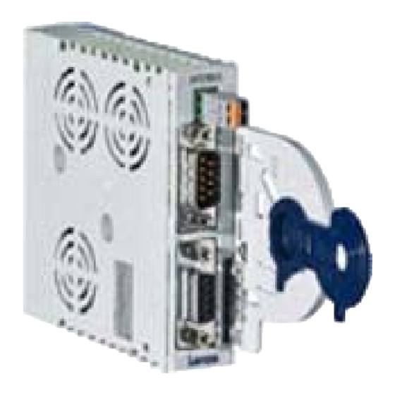
Wiring of the INTERBUS ( 24) LED status displays for diagnostic purposes E94YCIB001B LED status displays ( 47) [3-2] E94AYCIB communication module (INTERBUS) Lenze · E94AYCIB communication module (INTERBUS) · Communication Manual · DMS 4.0 EN · 02/2014 · TD17... -
Page 15: Technical Data
Servo Drives 9400 hardware manual Here you can find the ambient conditions and information on the electromagnetic compatibility (EMC) which also apply to the communication module. Lenze · E94AYCIB communication module (INTERBUS) · Communication Manual · DMS 4.0 EN · 02/2014 · TD17... -
Page 16: Protocol Data
Some codes may require a longer processing time (see reference manual/ »Engineer« online help for the Servo Drive 9400). There are no interdependencies between parameter data and process data. Lenze · E94AYCIB communication module (INTERBUS) · Communication Manual · DMS 4.0 EN · 02/2014 · TD17... -
Page 17: Protective Insulation
Danger! Dangerous voltage If the Servo Drives 9400 are operated on a phase earthed mains with a rated mains voltage 400 V, external measures need to be implemented in order to ensure protection against accidental contact. Possible consequences:... - Page 18 Basic insulation X206 X207 Functional insulation Ext. DC X205 MXI2 X107 Ext. DC X106 X105 X105 E94YCIB007 [4-1] Protective insulation in accordance with EN61800-5-1 Lenze · E94AYCIB communication module (INTERBUS) · Communication Manual · DMS 4.0 EN · 02/2014 · TD17...
- Page 19 • The separate potential area of the mains terminal has a "reinforced insulation". Result: The insulation between mains terminal X100 and the bus terminal is of the "reinforced insulation" type. Lenze · E94AYCIB communication module (INTERBUS) · Communication Manual · DMS 4.0 EN · 02/2014 · TD17...
-
Page 20: Dimensions
_ _ _ _ _ _ _ _ _ _ _ _ _ _ _ _ _ _ _ _ _ _ _ _ _ _ _ _ _ _ _ _ _ _ _ _ _ _ _ _ _ _ _ _ _ _ _ _ _ _ _ _ _ _ _ _ _ _ _ _ _ _ _ _ Dimensions a 89 mm b 134 mm b1 87 mm e 23 mm E94YCXX005 [4-2] Dimensions Lenze · E94AYCIB communication module (INTERBUS) · Communication Manual · DMS 4.0 EN · 02/2014 · TD17... -
Page 21: Installation
• Fieldbus communication is not possible or faulty. Protective measures • Before touching the module, be sure that you are free of electrostatic charge. Lenze · E94AYCIB communication module (INTERBUS) · Communication Manual · DMS 4.0 EN · 02/2014 · TD17... -
Page 22: Mechanical Installation
_ _ _ _ _ _ _ _ _ _ _ _ _ _ _ _ _ _ _ _ _ _ _ _ _ _ _ _ _ _ _ _ _ _ _ _ _ _ _ _ _ _ _ _ _ _ _ _ _ _ _ _ _ _ _ _ _ _ _ _ _ _ _ _ Mechanical installation 5.1.1 Assembly E94YCXX001G [5-1] Assembly 5.1.2 Disassembly E94AYCXX001H [5-2] Disassembly Lenze · E94AYCIB communication module (INTERBUS) · Communication Manual · DMS 4.0 EN · 02/2014 · TD17... -
Page 23: Electrical Installation
C Outgoing INTERBUS line at X207 (OUT) D Communication module in slot MXI1 of the Servo Drive 9400 E94YCXX008 [5-3] Wiring according to EMC guidelines Lenze · E94AYCIB communication module (INTERBUS) · Communication Manual · DMS 4.0 EN · 02/2014 · TD17... -
Page 24: Wiring Of The Interbus
500 kBit/s: £ 400 m 2 MBit/s: £ 150 m E94YCIB008 M: Master (e.g. PLC, Industrial PC) S1 ... Sn: Slaves [5-4] INTERBUS ring Lenze · E94AYCIB communication module (INTERBUS) · Communication Manual · DMS 4.0 EN · 02/2014 · TD17... -
Page 25: Interbus Connection
Vcc5 Output 5 V DC /DO1 Input RS485: DO1 inverted /DI1 Output RS485: DI1 inverted Vcc5 Output 5 V DC Free not assigned Lenze · E94AYCIB communication module (INTERBUS) · Communication Manual · DMS 4.0 EN · 02/2014 · TD17... -
Page 26: Dimensions Of 9-Pole Sub-D Connectors
Comply with the dimensions for width and depth of the 9-pole Sub-D connectors for the INTERBUS terminals X206/X207. E94YCIB001G [5-6] Dimensions of 9-pole sub-D connectors Lenze · E94AYCIB communication module (INTERBUS) · Communication Manual · DMS 4.0 EN · 02/2014 · TD17... -
Page 27: Bus Cable Specification
Select the baud rate which depends on the data volume, cycle time, and number of nodes just high enough to suit your application. Possible settings via DIP switch ( 30) Settings in »Engineer« ( 34) Lenze · E94AYCIB communication module (INTERBUS) · Communication Manual · DMS 4.0 EN · 02/2014 · TD17... -
Page 28: External Voltage Supply
With wire end ferrule, without plastic sleeve 1.5 mm (AWG 16) With wire end ferrule, with plastic sleeve 1.5 mm (AWG 16) Stripping length 9 mm Lenze · E94AYCIB communication module (INTERBUS) · Communication Manual · DMS 4.0 EN · 02/2014 · TD17... -
Page 29: Commissioning
Before switching on the Servo Drive 9400 and the communication module for the first time, check the entire wiring for completeness, short circuit and earth fault. Lenze · E94AYCIB communication module (INTERBUS) · Communication Manual · DMS 4.0 EN · 02/2014 · TD17... -
Page 30: Possible Settings Via Dip Switch
1 ... 10 words (16 bits/word). • Switch off the voltage supply of the communication module and afterwards on again to activate changed settings. Lenze · E94AYCIB communication module (INTERBUS) · Communication Manual · DMS 4.0 EN · 02/2014 · TD17... -
Page 31: Setting The Number Of Process Data Words
The communication module then operates internally with the following values: • 2 process data words (PD) • 1 parameter data word (PCP) DIP switch Number of Switch Max. number of PCP Lenze · E94AYCIB communication module (INTERBUS) · Communication Manual · DMS 4.0 EN · 02/2014 · TD17... -
Page 32: Setting The Number Of Parameter Data Words
• 2 process data words (PD) • 1 parameter data word (PCP) DIP switch Number of PCP Switch Max. number of ID code [hex] 0x03 0xE3 0xE0 0xE1 Lenze · E94AYCIB communication module (INTERBUS) · Communication Manual · DMS 4.0 EN · 02/2014 · TD17... -
Page 33: Setting The Baud Rate
/ C14863. DIP switch Switch 8 Baud rate Cable length between adjacent nodes 500 kbps max. 400 m 2 Mbps max. 150 m Lenze · E94AYCIB communication module (INTERBUS) · Communication Manual · DMS 4.0 EN · 02/2014 · TD17... -
Page 34: Settings In "Engineer
2. Carry out a "Reset node" of the node, or switch the voltage supply of the communication module off and then on again. Lenze · E94AYCIB communication module (INTERBUS) · Communication Manual · DMS 4.0 EN · 02/2014 · TD17... -
Page 35: Initial Switch-On
• An explicit controller enable causes the drive to start up in a controlled manner: LOW- HIGH edge at digital input X5/RFR. C00142 = "1: Enabled" • An uncontrolled restart of the drive is possible. Lenze · E94AYCIB communication module (INTERBUS) · Communication Manual · DMS 4.0 EN · 02/2014 · TD17... -
Page 36: Data Transfer
• Input data (Rx data): Process data from the inverter (slave) to the master • Output data (Tx data): Process data from the master to the inverter (slave) Lenze · E94AYCIB communication module (INTERBUS) · Communication Manual · DMS 4.0 EN · 02/2014 · TD17... -
Page 37: Process Data Transfer
»Engineer« is provided with a port configurator. Note! • The port mapping for the Servo Drive 9400 is no configuration that can be carried out online. For this purpose, an update of the »Engineer« project and a subsequent download of the application is always required. - Page 38 If the »FB Editor« is activated, the multiplexer codes (> C03000) are no longer available. In this case, you must carry out the interconnection directly in the »FB Editor«. Lenze · E94AYCIB communication module (INTERBUS) · Communication Manual · DMS 4.0 EN · 02/2014 · TD17...
-
Page 39: Parameter Data Transfer
( 53) Addressing of the parameter data The parameters of a Lenze device are not directly addressed via codes but via an index and subindex. The conversion is made via an offset: 24575 or 0x5FFF • INTERBUS index (decimal) = 24575 - Lenze code number (decimal) •... -
Page 40: Initialising Pcp Communication
Max-PDU Sending-High-Prio Max-PDU Sending-Low-Prio Max-PDU Receiving-High-Prio Max-PDU Receiving-Low-Prio Supported Services Request 0x803000 Supported Services Response 0x000000 Maximum SCC Maximum RCC Maximum SAC Maximum RAC Lenze · E94AYCIB communication module (INTERBUS) · Communication Manual · DMS 4.0 EN · 02/2014 · TD17... -
Page 41: Supported Pms Services
The "Abort" PMS service aborts a logic connection between the INTERBUS master and the communication module. 9.3.3 Reject The "Reject" PMS service rejects a non-supported PMS service. Lenze · E94AYCIB communication module (INTERBUS) · Communication Manual · DMS 4.0 EN · 02/2014 · TD17... -
Page 42: Read/Write
0x43 General collision with other values 9.3.5 Get-OD The "Get-OD" PMS service reads out the object description for every parameter and data type. Lenze · E94AYCIB communication module (INTERBUS) · Communication Manual · DMS 4.0 EN · 02/2014 · TD17... -
Page 43: Identify
["xx"] and build status ["yy"]) Blank 7 ... 11 Firmware version of the communication module (from C13902 C14902 = "01.00.xx", without internal revision status ["xx"]) 12...15 Blank Lenze · E94AYCIB communication module (INTERBUS) · Communication Manual · DMS 4.0 EN · 02/2014 · TD17... -
Page 44: Status
• 1 = ready for operation to a limited extent inverter. (all other device states) Local Detail Is not supported. Lenze · E94AYCIB communication module (INTERBUS) · Communication Manual · DMS 4.0 EN · 02/2014 · TD17... -
Page 45: Monitoring
[0x00c88131]" ( 52). If the Servo Drive 9400 does not receive any valid process data in the "IBS-ACTIVE" state, the setting C13885 C14885 is taken as a basis for the process data. (Like this the data sent last by the master can be used or reset to zero.) -
Page 46: Interruption Of Internal Communication
The response to a communication error between the communication module and the Servo Drive 9400 can be set via these codes: • C01501 (module in slot MXI1) • C01502 (module in slot MXI2) Lenze · E94AYCIB communication module (INTERBUS) · Communication Manual · DMS 4.0 EN · 02/2014 · TD17... -
Page 47: Diagnostics
The communication module is not accepted by the basic device or the basic device is not active (see notes in the documentation relating to the basic device.) Lenze · E94AYCIB communication module (INTERBUS) · Communication Manual · DMS 4.0 EN · 02/2014 · TD17... -
Page 48: Diagnosing With The "Engineer
The bus is active. Data cycles are executed. 0xyyy2 IBS-READY The bus is ready for operation. No data cycles are executed. yyy = device-internal use Lenze · E94AYCIB communication module (INTERBUS) · Communication Manual · DMS 4.0 EN · 02/2014 · TD17... -
Page 49: Error Messages
_ _ _ _ _ _ _ _ _ _ _ _ _ _ _ _ _ _ _ _ _ _ _ _ _ _ _ _ _ _ _ _ _ _ _ _ _ _ _ _ _ _ _ _ _ _ _ _ _ _ _ _ _ _ _ _ _ _ _ _ _ _ _ _ Error messages This chapter supplements the error list for the Servo Drive 9400 contained in the reference manual and in the »Engineer« online help with the error messages of the communication module. -
Page 50: Possible Causes And Remedies
None System fault Fault Trouble Quick stop by trouble Warning locked Warning Information Cause Remedy Module is defective. Send module with error description to Lenze. Lenze · E94AYCIB communication module (INTERBUS) · Communication Manual · DMS 4.0 EN · 02/2014 · TD17... - Page 51 None System fault Fault Trouble Quick stop by trouble Warning locked warning Information Cause Remedy Error when processing the INTERBUS services Execute renewed initialisation by the master. Lenze · E94AYCIB communication module (INTERBUS) · Communication Manual · DMS 4.0 EN · 02/2014 · TD17...
- Page 52 Configuring process data (PDO mapping) ( 37) words) has to consist of 1 ... 10 words (16 bits/word). Setting the number of process data words ( 31) Lenze · E94AYCIB communication module (INTERBUS) · Communication Manual · DMS 4.0 EN · 02/2014 · TD17...
-
Page 53: Parameter Reference
_ _ _ _ _ _ _ _ _ _ _ _ _ _ _ _ _ _ _ _ _ _ _ _ _ _ _ _ _ _ _ _ _ _ _ _ _ _ _ _ _ _ _ _ _ _ _ _ _ _ _ _ _ _ _ _ _ _ _ _ _ _ _ _ Parameter reference This chapter supplements the parameter list and the table of attributes contained in the reference manual and in the »Engineer« online help for the Servo Drive 9400 with the parameters of the E94AYCIB (INTERBUS) communication module. ... - Page 54 3 Quick stop by trouble 4 Warning Locked 5 Warning Read access Write access CINH PLC-STOP No transfer Lenze · E94AYCIB communication module (INTERBUS) · Communication Manual · DMS 4.0 EN · 02/2014 · TD17...
-
Page 55: Parameters Of The Communication Module For Slot Mxi1
C13531/1 C13531/32 Read access Write access CINH PLC-STOP No transfer PDO_MAP_RX PDO_MAP_TX COM MOT Lenze · E94AYCIB communication module (INTERBUS) · Communication Manual · DMS 4.0 EN · 02/2014 · TD17... - Page 56 C13851/1 C13851/32 Read access Write access CINH PLC-STOP No transfer PDO_MAP_RX PDO_MAP_TX COM MOT Lenze · E94AYCIB communication module (INTERBUS) · Communication Manual · DMS 4.0 EN · 02/2014 · TD17...
- Page 57 Length of the ports entered into the receive PDO Read access Write access CINH PLC-STOP No transfer PDO_MAP_RX PDO_MAP_TX COM MOT Lenze · E94AYCIB communication module (INTERBUS) · Communication Manual · DMS 4.0 EN · 02/2014 · TD17...
- Page 58 Bit 15 Bit 15 Read access Write access CINH PLC-STOP No transfer PDO_MAP_RX PDO_MAP_TX COM MOT Lenze · E94AYCIB communication module (INTERBUS) · Communication Manual · DMS 4.0 EN · 02/2014 · TD17...
- Page 59 Response to interrupted INTERBUS communication Read access Write access CINH PLC-STOP No transfer PDO_MAP_RX PDO_MAP_TX COM MOT Lenze · E94AYCIB communication module (INTERBUS) · Communication Manual · DMS 4.0 EN · 02/2014 · TD17...
- Page 60 4 4 words Read access Write access CINH PLC-STOP No transfer PDO_MAP_RX PDO_MAP_TX COM MOT Lenze · E94AYCIB communication module (INTERBUS) · Communication Manual · DMS 4.0 EN · 02/2014 · TD17...
- Page 61 • The following identification code is displayed: "E94AFCIB". Read access Write access CINH PLC-STOP No transfer PDO_MAP_RX PDO_MAP_TX COM MOT Lenze · E94AYCIB communication module (INTERBUS) · Communication Manual · DMS 4.0 EN · 02/2014 · TD17...
- Page 62 Bit 7 DIP 1 Read access Write access CINH PLC-STOP No transfer PDO_MAP_RX PDO_MAP_TX COM MOT Lenze · E94AYCIB communication module (INTERBUS) · Communication Manual · DMS 4.0 EN · 02/2014 · TD17...
-
Page 63: Parameters Of The Communication Module For Slot Mxi2
C14531/1 C14531/32 Read access Write access CINH PLC-STOP No transfer PDO_MAP_RX PDO_MAP_TX COM MOT Lenze · E94AYCIB communication module (INTERBUS) · Communication Manual · DMS 4.0 EN · 02/2014 · TD17... - Page 64 C14851/1 C14851/32 Read access Write access CINH PLC-STOP No transfer PDO_MAP_RX PDO_MAP_TX COM MOT Lenze · E94AYCIB communication module (INTERBUS) · Communication Manual · DMS 4.0 EN · 02/2014 · TD17...
- Page 65 Length of the ports entered into the receive PDO Read access Write access CINH PLC-STOP No transfer PDO_MAP_RX PDO_MAP_TX COM MOT Lenze · E94AYCIB communication module (INTERBUS) · Communication Manual · DMS 4.0 EN · 02/2014 · TD17...
- Page 66 Bit 15 Bit 15 Read access Write access CINH PLC-STOP No transfer PDO_MAP_RX PDO_MAP_TX COM MOT Lenze · E94AYCIB communication module (INTERBUS) · Communication Manual · DMS 4.0 EN · 02/2014 · TD17...
- Page 67 Response to interrupted INTERBUS communication Read access Write access CINH PLC-STOP No transfer PDO_MAP_RX PDO_MAP_TX COM MOT Lenze · E94AYCIB communication module (INTERBUS) · Communication Manual · DMS 4.0 EN · 02/2014 · TD17...
- Page 68 4 4 words Read access Write access CINH PLC-STOP No transfer PDO_MAP_RX PDO_MAP_TX COM MOT Lenze · E94AYCIB communication module (INTERBUS) · Communication Manual · DMS 4.0 EN · 02/2014 · TD17...
- Page 69 • The following identification code is displayed: "E94AFCIB". Read access Write access CINH PLC-STOP No transfer PDO_MAP_RX PDO_MAP_TX COM MOT Lenze · E94AYCIB communication module (INTERBUS) · Communication Manual · DMS 4.0 EN · 02/2014 · TD17...
- Page 70 Bit 7 DIP 1 Read access Write access CINH PLC-STOP No transfer PDO_MAP_RX PDO_MAP_TX COM MOT Lenze · E94AYCIB communication module (INTERBUS) · Communication Manual · DMS 4.0 EN · 02/2014 · TD17...
-
Page 71: Table Of Attributes
Read access Reading permitted Write access Writing permitted CINH Controller inhibit required Writing is only possible if controller inhibit is set Lenze · E94AYCIB communication module (INTERBUS) · Communication Manual · DMS 4.0 EN · 02/2014 · TD17... - Page 72 Baud rate 9681 0x25D1 UNSIGNED_8 C14900 Firmware product type 9675 0x25CB VISIBLE_STRING C14901 Firmware compilation date 9674 0x25CA VISIBLE_STRING Lenze · E94AYCIB communication module (INTERBUS) · Communication Manual · DMS 4.0 EN · 02/2014 · TD17...
- Page 73 Name Index Data Access Factor CINH C14902 Firmware version 9673 0x25C9 VISIBLE_STRING C14920 Display of DIP switch position 9655 0x25B7 BITFIELD_8 Lenze · E94AYCIB communication module (INTERBUS) · Communication Manual · DMS 4.0 EN · 02/2014 · TD17...
-
Page 74: Index
C13863 | Active baud rate Counter (C14862) C13880 | Monitoring Reaction CRL (communication relation list) C13881 | Response time if the INTERBUS communication is interrupted Lenze · E94AYCIB communication module (INTERBUS) · Communication Manual · DMS 4.0 EN · 02/2014 · TD17... - Page 75 Length of ports mapped into receive PDO (C14854) Firmware version (C14902) Length of ports mapped into send PDO (C13855) Length of ports mapped into send PDO (C14855) Lenze · E94AYCIB communication module (INTERBUS) · Communication Manual · DMS 4.0 EN · 02/2014 · TD17...
- Page 76 Using the communication module Querying the current bus status Voltage supply Voltage supply (external) Wiring according to EMC guidelines Wiring of the INTERBUS Write (PCP service) Lenze · E94AYCIB communication module (INTERBUS) · Communication Manual · DMS 4.0 EN · 02/2014 · TD17...
-
Page 77: Your Opinion Is Important To Us
Perhaps we have not succeeded in achieving this objective in every respect. If you have suggestions for improvement, please e-mail us feedback-docu@lenze.com Thank you very much for your support. Your Lenze documentation team... - Page 78 E94AYCIB communication module (INTERBUS) · Communication Manual · EDS94AYCIB · 13451099 · DMS 4.0 EN · 02/2014 · TD17 Lenze Automation GmbH Postfach 10 13 52, D-31763 Hameln Hans-Lenze-Straße 1, D-31855 Aerzen Germany +49 5154 82-0 +49 5154 82-2800 lenze@lenze.com www.lenze.com...
Need help?
Do you have a question about the 9400 and is the answer not in the manual?
Questions and answers