
Related Manuals for KEF PSD 5


Summary of Contents for KEF PSD 5
- Page 1 Industrivej 3-9 KEF-MOTOR A/S DK 9460 Brovst Tel. +45 9823 6266 Fax. +45 9823 6144 25.04.12 Instruction Manual PSD 5 – BO 50/5 – POD 5 - PODA 5 Industrial Grinders...
- Page 2 Fax: +45 98 23 61 44 hereby declares that KEF Double Ended Grinder PSD 5, BO 50-5, POD 5 are manufactured in accordance with the provisions of the COUNCIL DIRECTIVE of 17. May 2006 (2006/42/EC) – The Machinery Directive (order no. 561 of 25 June 1994 with subsequent amendments) Also on accordance with: ...
-
Page 3: Table Of Contents
PSD 5 COVER PSD 5 BELT ARM VFCB- PSD 5 EXHAUST SYSTEM FOR POD 5 SPINDLE PODA 5 EBURRING COVER FOR TECHNICAL DATA ECHNICAL SPECIFICATIONS IMENSIONS IRING DIAGRAM WITCH W EMERGENCY STOP 8.5 PSD 5 EX16 D CONNECTED TO XTRACTION UARANTEE... -
Page 4: Transport & Handling
1 Transport & handling Transport PSD 5 Industrial belt grinder and others are delivered on a pallet packed in protective wrapping. Handling The machines can easily be transported on the pallet on which they are delivered. If the machine is delivered on a pedestal you must insure that the pedestal is secured to the pallet. -
Page 5: Directions For Use
2 Directions for use Operation After adjustment and connection the machine is ready for use. The grinding kan take place by the contact wheel (E) or on the surface grinding table by opening the cover (H). When you start grinding please start by letting the material touch the grinding wheel lightly and thereby avoid pressuring the grinding wheel to prolonge the lifetime of it. -
Page 6: Deburring Cover For Poda
9. Don’t force tool. It will 8. Make workshop kidproof with do the job better and be padlocks, master safer at the rate for switches, or by which it was designed. removing starter keys. 10. Use right tool. 11. Wear proper apparel. Wear no loose clothing, Don’t force tool or gloves, neckties, rings, attachment to do... -
Page 7: Maintenance
Maintenance Keep the machine in a dry place so the grinding wheels or belts will not risk getting any damp or rain. The grinding wheel will often get uneven because of use and therefore we recommend that you level the grinding wheel off frequently. When the grinding wheel is worn more than 25% we recommend that you change to a new wheel. -
Page 8: Belt Arm
3 Belt Arm Assembly and mounting of belt arm If the grinding machine is mounted with a grinder cover or a deburrer cover these must be removed completely before mounting the belt arm. Mount the telescopearm (A) to the cover (B) by using the fitting for the telescope arm (C) and mounting the cover (B) by putting a screw through the side plate into the holder for the telescopearm (D). -
Page 9: Changing Of Grinding Belt
Changing of grinding belt When the grinding belt is worn out it must be replaced which is done the following way: The top plate (A) (se fig.: 3.2) on the cover is opened and the handle (B) is pulled down. This way the pressure on the grinding belt will be lowered (C), so that it can be dismounted and a new grinding belt can be mounted in reverse order. -
Page 10: Maintenance Of Belt Arm
Maintenance of belt arm Empty the spark arrester (A) (see fig.: 3.3) to avoid hot sparks damaging or deforming grinding belt and contact wheel. If the machine is equipped with VFCB- exhaust unit you must control if the suction channels need cleaning. The dust bag must be emptied when necessary. -
Page 11: Vfcb-Complete Exhaust Unit
(J) can be mounted on the exhaust connecting unit (I). In case the VFCB-exhaust unit is mounted on the PSD 5 double grinder, the casted pipe bendings (K) can be used to mount the VFCB-exhaust unit on the grinding machine by what the guard (A) and the suction hoses (G) with accessories can be left out. -
Page 12: Deburrer
5 Deburrer Assembling and mounting of deburrer The deburrer cover is to be assembled in the order shown in fig.: 5.1. The four screws in the end cover (A) must be unscrewed and the mounting plate (B) is to be placed on the end cover (A), the four countersinked machine screws M6x20 (C) are retightened. -
Page 13: Maintenance Of Deburrer/Steel Brush
Maintenance of deburrer/steel brush Nothing on the deburrer/steel brush needs maintenance except that it is necessary to adjust the grinding system as the steel brush is worn. The eye shield and other accessories must be replaced immediately if they are damaged. Use of deburrer When the deburrer cover is correctly mounted the grinding system (A) (see fig.: 5.2) needs adjusting which is done by adjusting the height of the grinding system when the screw (B) -
Page 14: Polishing Machine
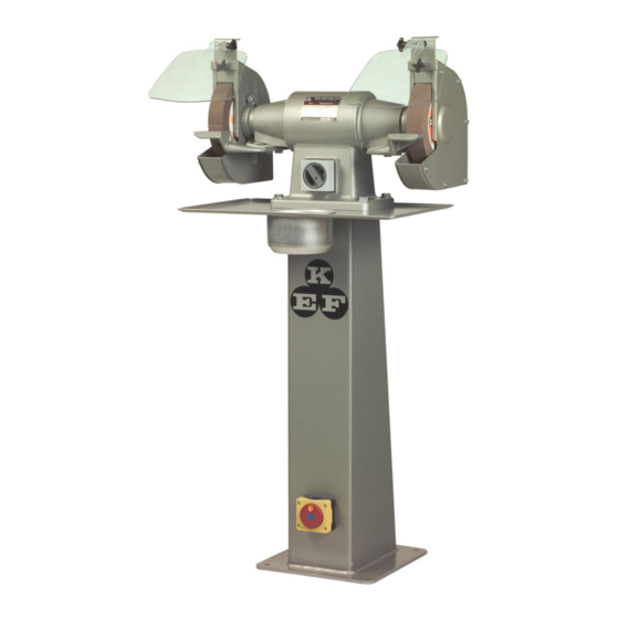
6 Polishing machine Adjustment the polishing machine. Placing of the machine must take place on a firm and level surface. Now secure the polishing machine to the work table or the floor by using the four holes in the base used for mounting the machine to the pallet. -
Page 15: Spare Parts
7 Spare parts In this chapter there are split drawings and matching spare parts lists. Machine line up of PSD 5 Fig.: 7.1 (A) Motorpart, (B) Grinding cover, (C) Belt arm, (D) VFCB-exhaust unit. -
Page 16: Psd 5 Basic Model
PSD 5 basic model Fig.:7.2 Drawing of PSD 5 basic model Spare parts list for PSD 5 basic model Pos.nr. Type Ident. Nr. Collar bushing E 308 0995681 Screw M6x20 CH Z 4345678 Bearing end shield V 0187860 O-ring 50x45x3 mm 1385259 Wave spring 50x44x0.6... -
Page 17: Psd 5 Cover
PSD 5 cover Fig.: 7.3 Split drawing of PSD 5 cover Spare parts list for PSD 5 cover Pos.nr. Type Cover L Cover R Eye shield for PSD 5 1311948 1311948 Cross handle Ø32 M6 DIN 6335 0922021 0922021 Disc 6.4x1.6... -
Page 18: Psd 5 Belt Arm
PSD 5 belt arm Fig.: 7.4 Split drawing of PSD 5 belt arm... - Page 19 Spare parts list for PSD 5 belt arm Order number Pos. Nr. Type Right Left Top screw 2078212 2078212 Sliding pipe for belt stand 9480687 9480687 Machine screw M4x4 Z 0737618 0737618 Lock ring DIM 42, DIN 472 7655123 7655123...
-
Page 20: Vfcb-Exhaust System For Psd
VFCB-exhaust system for PSD 5 Fig.: 7.5 Split drawing of VFCB-exhaust system for PSD 5... - Page 21 Elbow for VFCB 0111729 0111729 Pedestal for PSD 5 1065094 1065094 Table PSD 5* 0771317 0771317 Water cup 0771333 0771333 Disc ø13x24x2.5 0105167 0105167 Screw M12x40 Z 7654320 7654320 Table for PSD 5 with belt arm or deburrer has nr.: 077131...
-
Page 22: D Eburring Cover For Poda 5
Cover L Disc 6.4x1.6 0737631 0737631 Cross handle ø32 M6 DIN 6335 0922021 0922021 Bolt for wood 6x50 0932043 0932043 Eye protective guard PSD 5 1311948 1311948 Nut M10 Z 0516637 0516637 Washer 10.2 0132608 0132608 Chest screw M10 1311956... - Page 23 POD 5 w/flange Fig 7.7 Split drawing of POD 5 w/flange Spare parts list for POD 5 w/flange Pos.nr. Type Left Right Polishing guard Left 0921432 0921434 Disk 6mm 0737631 0737631 Skrew M6x10 0110089 0110089 Distance ring ø20x30x6 1551176 1551176 Spindle 1532367 1532375...
-
Page 24: Pod 5 W/Spindle
POD 5 w/spindle Fig 7.8 Split drawing of POD 5 w/spindle Spare parts list for POD 5 w/spindle Pos.nr. Type Left Right Polishing guard Left 0921432 0921434 Disk 6mm 0737631 0737631 Skrew M6x10 0110089 0110089 Flange inner 0921572 0921572 Polishing Mop ø200x20xø6 1531506 1531506 Flange outer... -
Page 25: Technical Data
0,81 Weight The noise level for these machines varies from 76 dB(A) (PSD 5/POD 5) to 88 dB(A) (BO 50/5) according to the measuring directions in the Department for Work Safety and Health notice nr. 561 on devices of technical aids. Eye and ear protection must be worn during use of the above machines. -
Page 26: Wiring Diagram
Wiring diagrams PSD 5, BO 50/5 and POD 5 industrial grinding machines can be wired 3 x 400 V, 50/60 Hz or 3 x 230 V 50/60 Hz. Please see wiring diagrams below. Max. Volt Max. Volt... -
Page 27: Disa Switch W/Emergency Stop
Disa Switch w/emergency stop... -
Page 28: Psd 5 Connected To Ex16 Dust Extraction
8.5 PSD 5 connected to EX16 Dust Extraction... -
Page 29: Guarantee
Guarantee If within 2 year of purchase this machine supplied by KEF A/S becomes defective due to faulty materials or workmanship we guarantee to repair or replace the machine or defective part or parts free of charge provided that: 1. The product is returned complete to one of our Service Branches or Official Service Agents.
Need help?
Do you have a question about the PSD 5 and is the answer not in the manual?
Questions and answers