Table of Contents
Advertisement
Quick Links
Advertisement
Table of Contents

Related Manuals for KEF BSH 20-75CGC


Summary of Contents for KEF BSH 20-75CGC
- Page 1 Instructions for Use of Centerless Belt Grinder KEF BSH 20-75CGC...
- Page 2 PLEASE READ THIS MANUAL BEFORE USE...
- Page 3 Tel.: +45 98 23 62 66 Fax.: +45 98 23 61 44 hereby declares that KEF Centerless Belt Grinder Model BSH 20-75CGC are manufactured in accordance with the provisions of the European Parliament and Council Directive 2006/42 / EC of...
-
Page 4: Table Of Contents
Contents TRANSPORT 1.1 T RANSPORT 1.2 P ARTS OF THE MACHINE PREPARATION 2.1 A SSEMBLY 2.2 T HE POSITIONS ARE OPEN AND CLOSED 3.1 S ELECTION OF SUPPORT 3.2 S ETTING THE FORK 3.3 P UTTING THE ARTICLE IN THE MACHINE 3.4 L OCATION OF DISTANCE STOP 3.5 S... -
Page 5: Transport
1.0 Transport 1.1 Transport The centerless grinding jig is delivered on a pallet of size 120cm x 80cm (48x32 inch). On the pallet there are (see diagram 1.1): 1. A belt grinder (A) 2. Base (E) (without right tray) with centerless jig and support roller. 3. -
Page 6: Parts Of The Machine
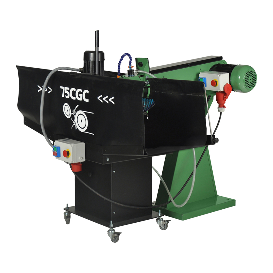
1.2 Parts of the machine Diagram 1.1: Overview of Centerless grinding jig CGC 75... - Page 7 Front of the belt grinder Pipe holder Propulsion jig Support ( roller or Teflon) Base Right tray Mounting arm Leg for base unit Driving wheel...
-
Page 8: Preparation
2.0 Preparation 2.1 Assembly Assemble the received parts as follows. (See diagram 1.1) 1. Install the right tray on the base. 2. Tilt the motor up in the vertical position and tighten legs to the base frame (H). 3. Place the curtain rods in the trays together and hang the curtains up (see diagram 2.1). - Page 9 4. Fasten the belt grinder to the floor. 5. Roll the base under the front edge of the belt grinder. 6. Assemble the mounting arm (G) below the fork of the belt grind (K) with the supplied screws. (See diagram 2.2) Diagram 2.2: Assembly of curtains and curtain rods.
-
Page 10: The Positions Are Open And Closed
2.2 The positions are open and closed See below how BSH 20-75 CGC can be opened and closed. Diagram 2.3: CGC 75 in the closed position. Diagram 2.4: BSH 20-75CGC in the open position. -
Page 11: Selection Of Support
3.0 Operation The machine must be adjusted again for each tube dimension. Then the feed rate and direction are set. 3.1 Selection of support For each tube dimension, the machine must be adjusted again. The tube dimension determines the support to be used in frame. Below the fork is mounted support roller (A) and Teflon support plate (B) respectively. -
Page 12: Setting The Fork
larger than Ø25 and the support plate is used for the smaller tube dimensions smaller than Ø25. 3.2 Setting the fork The fork height is set depending on the tube dimension Ø(inch). Loosen the lever and move the fork to the tube dimension, which is to be processed. The scale on the left is used with the help of the support Teflon. - Page 13 Diagram 3.3: Centre of centre for safety...
-
Page 14: Location Of Distance Stop
3.4 Location of distance stop The drive wheel should NEVER come in contact with the sanding belt. The distance stop is a safety precaution so that this can be avoided. For each pip dimension the distance stop must be adjusted, in order to avoid that the propulsion jig tilts down and comes in contact with the sanding belt. -
Page 15: Selection Of Speed Of Belt Grinder
This applies especially during the final polishing stage. KEF Group offers a starter pack of the above sanding belts in grades adapted to the processes: cleaning, finishing and polishing. Upon delivery, the standard sanding belt is VSM K180 on the belt grinder. -
Page 16: Operation Of The Centerless Jig
Diagram 3.5: Propulsion. If you turn the lever (2) to the right, feeding can take place from the left and vice versa. In addition, the feed speed depends on how far the lever is turned out to either the right or left side. Angles around 3-5 degrees will be sufficient for a good feed speed. It is necessary to experiment for each type of article. -
Page 17: Safety Rules For Stationary Power Tools
3.10 Safety rules for stationary power tools. Følg disse regler for at få det bedste resultat og den bedste udnyttelse af Deres nye maskine. The good craftsman 1. Know your power tool. Read the owner’s respects the tools with manual carefully. Learn its applications and which he works. - Page 18 8. Make workshop 9. Don’t force tool. It will do the job better kid proof with and be safer at the rate for which it was padlocks, master designed. switches, or by removing starter keys. 10. Use right 11. Wear proper apparel. Wear no loose tool.
- Page 19 16. Disconnect tools 17. Reduce the risk of before servicing and when unintentional changing accessories starting. Make sure such as grinding wheels, switch is in off polishing mops, grinding position before belts, blades, bits, cutters, plugging in. etc. 18. Use recommended accessories. Consult owner’s manual for recommended accessories.
-
Page 20: Spare Parts
4.0 Spare parts When ordering spare parts, the production number and the serial number must be furnished. The spare parts are divided into the Centerless jig and belt grinder. Please note that there are a few parts that have been removed from belt grinder in connection with preparation for shipment of the centerless belt grinder. -
Page 21: Centerless Grinding Jig (Cgc)
4.1 Centerless grinding jig (CGC) Diagram: 4.1: Parts drawing for Centerless CGC 75... - Page 22 Spare parts list for Centerless CGC 75 Pos. Nr. Beskrivelse Anta CGC 75 Sokkel 8501122 Bakke højre 8501188 Bakke venstre 8501187 Frontplade 8501114 Unbracobolt M6x12 0120621 Møtrik M10 5438761 Stålsætbolt M8x12 0300144 Skive ø22xø10x1,2 0105132 Hjul m/bremse 0129000 Stålsætbolt M10x55 0110107 Afbryder Tripus-3x400V-7,5A 0188852...
- Page 23 Afstandsstop 8501147 Frontdel 8501165 Håndtag for slibeanlæg 0233808 Stålsætbolt M8x16 0231586 Håndtag kpl. 1055910 Bespændingsplade f/gearhus 1055691 Afstandsrør f/bolt t/motor 1055880 Unbracobolt 6x20 0331796 Bræddebolt M6x50 special 1055881 Låsemøtrik M6 0951406 Vippebeslag 8501156 Snekkegear 0300250 Motor 0,25 kW 2030015 Aksel for drivhjul 1055771 Gaffel 8501254...
-
Page 24: Belt Grinder Without Exhaust
4.2 Belt grinder without exhaust Diagram 4.2: Parts drawing of belt grinder without exhaust Spare parts list of belt grinder without exhaust... - Page 25 Item No. Description 20-75 Belt release handle 0102267 Belt guard 0239202 Grinding stop/Cover Blue 0880002 Eye shield 0233605 Split pin ø6x50 mm 0233050 Tool rest 0233207 Handle for tool rest 0233808 Bolt M10x25 0300134 Support for tool rest 0104373 Handle M6x25 0233025 Fan cover for motor Screw M8x12...
-
Page 26: Optional Equipment
Screw M4x8 0100425 Lock nut M6 0951406 Hinge mounting for eye shields 0921475 Disc 8mm 6540981 Lock ring Ø20 0311262 Shaft 0233251 Lock ring Ø7 0915720 Rubber Strip 1055860 Screw M6x12 0930612 Wave spring 14x0.3x21 0102268 Eccentric for 8 mm motor sheet 0752262 Disc 8mm 6540981... -
Page 27: Specifications
Contact wheel Ø200x75 Weight 76 kg The noise level for KEF belt grinding machine has been measured to 80 dB (A) according to the measuring instruction in the note 561 from the Work Inspection Department on device of technical aids. -
Page 28: Electrical Diagram
5.2 Electrical diagram Diagram: 5.1 Diagram for belt grinder with two speeds and without exhaust motor. -
Page 29: Garantee
6.0 Garantee If within 2 year of purchase this machine supplied by KEF-MOTOR A/S becomes defective due to faulty materials or workmanship we guarantee to repair or replace the machine or defective part or parts free of charge provided that: 1.
Need help?
Do you have a question about the BSH 20-75CGC and is the answer not in the manual?
Questions and answers