
Related Manuals for Nortel SR1001


Summary of Contents for Nortel SR1001
- Page 1 Part No. 322004-A March 2006 4655 Great America Parkway Santa Clara, CA 95054 SR1001 Installation Guide Nortel Secure Routers 1001 and 1001S Software Release 8.3.5...
-
Page 2: Restricted Rights Legend
In the interest of improving internal design, operational function, and/or reliability, Nortel Networks reserves the right to make changes to the products described in this document without notice. Nortel Networks does not assume any liability that may occur due to the use or application of the product(s) or circuit layout(s) described herein. -
Page 3: How To Get Help
Customer or in the event designated hardware or CFE is no longer in use, Customer will promptly return the Software to Nortel Networks or certify its destruction. Nortel Networks may audit by remote polling or other reasonable means to determine Customer’s Software activation or usage levels. -
Page 4: Getting Help Through A Nortel Distributor Or Reseller
Getting help over the phone from a Nortel Solutions Center If you do not find the information you require on the Nortel Technical Support web site, and have a Nortel support contract, you can also get help over the phone from a Nortel Solutions Center. -
Page 5: Table Of Contents
ONTENTS BOUT UIDE Organization............................2 Conventions ............................3 Notices ............................3 Documentation ........................... 4 About the Nortel Secure Router Documentation CD..............4 Navigation ..........................4 Printing Documents........................4 Related Nortel Guides ........................4 RODUCT NTRODUCTION Overview ............................7 1001..............................8 1001 Front Panel .......................... - Page 6 Other Tests ............................. 50 Loopback Test ..........................50 BERT Test ..........................50 Diagnostics Tips ..........................51 General Symptoms ......................... 51 PECIFICATIONS Secure Router Specifications ......................55 WAN Interfaces..........................56 LAN Interfaces ..........................57 Cable Pinouts..........................58 MIBs..............................63 SR1001 Installation Guide Version 8.3.5...
- Page 7 OMPLIANCE AND TANDARDS Compliance ............................65 FCC Conformance ..........................66 FCC Part 15............................ 66 FCC Part 68............................ 66 Incidence of Harm.......................... 66 Rights of the Telephone Company....................67 Proper Disposal of Nortel Equipment ....................68 NDEX SR1001 Installation Guide Version 8.3.5...
- Page 8 SR1001 Installation Guide Version 8.3.5...
- Page 9 10 Wall-Mount Components......................17 11 Rack-Mount Components ......................18 12 Table Top Installation ........................ 19 13 Wall Mounting the SR1001 and SR1001S ................20 14 Rack Mounting the SR1001....................... 21 15 Connecting the Ethernet Cable ....................22 16 Connecting the WAN Cable ..................... 23 17 Connecting the Console Cable (Local Management) ..............
- Page 10 SR1001 Installation Guide Version 8.3.5...
- Page 11 21 Specifications: V.35 Interface..................... 57 22 Specifications: Ethernet LAN Interface ..................58 23 Miscellaneous..........................58 24 Pinouts: Nortel-to-Terminal Console Cable (DB-9) ..............58 25 Pinouts: Ethernet Cable (RJ-45) ....................59 26 Pinouts: WAN Cable (RJ-48C)....................59 27 DB-25 to RJ-45 Modem Adapter Pinouts................... 59 28 Pinouts: Serial Connector (DTE) ....................
- Page 12 SR1001 Installation Guide Version 8.3.5...
-
Page 13: About This Guide
UIDE Detailed instructions are provided in this guide for installing, configuring, and troubleshooting the Nortel Secure Router 1001 and 1001Serial (1001S). This guide is designed for network managers, administrators, and technicians who are responsible for the installation and management of networking equipment in Enterprise and Service Provider environments. -
Page 14: Organization
Product Introduction - provides a description of installation site requirements, and cables and tools required for installing the SR1001. Installation - describes the system front and back panels and how to install the SR1001. Information is also provided about the operator interface, network cabling, and the operator interface. -
Page 15: Conventions
Notices Notice paragraphs alert you about issues that require your attention. The following paragraphs describe the types of notices used in this guide. Notes provide tips and useful information regarding the installation and operation of Nortel NOTE: Secure Routers. ESD notices provide information about how to avoid discharge of static electricity and subsequent ESD: damage to Nortel Secure Routers. -
Page 16: Documentation
Documentation Nortel user guides, which are provided in portable document format (PDF), are included on the Nortel Secure Router Documentation CD-ROM that ships with the SR1001. The PDF files are also available on the Nortel website: www.nortel.com To view PDF files, Adobe Acrobat® Reader® 4.0, or newer, must be installed on your workstation. - Page 17 This guide provides descriptions of commands available for Nortel implementation of BGP (including BGP4), OSPF, RIP and other routing protocols. SR1001 Configuration Guide This guide provides example configurations. SR1001 Web UI User Guide This guide explains how to configure the SR1001 using the Web UI. SR1001 Installation Guide Version 8.3.5...
- Page 18 CHAPTER 1 About This Guide Documentation SR1001 Installation Guide Version 8.3.5...
-
Page 19: Product Introduction
WAN port, two 10/100 Fast Ethernet ports, an AUX port, an ISDN backup port, ac compact flash slot, and a local/remote management Console port. In addition to the command line interface, the SR1001 supports a Web User Interface which can be used to configure basic operational and security features. For more information on the Web UI, refer to the SR1001 Web UI User Guide. -
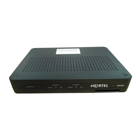
Page 20: 1001 Front Panel
Indicates traffic activity Green = link is operational on this interface Blinking Yellow = either receiving or sending traffic Red = packet collisions Indicates traffic speed Off = 10 Mbps on the interface Green = 100 Mbps SR1001 Installation Guide Version 8.3.5... -
Page 21: Led And Port Descriptions
Console management port. This port accepts a cable with an RJ-45 cable connector. DC power 12 VDC power connection. This port accepts the 2 mm. power connector on the DC power supply cable that ships with the 1002 router. SR1001 Installation Guide Version 8.3.5... -
Page 22: 1001 Serial
1001 Serial 1001S Front Panel The router front panel houses the Secure Router LEDs. Figure 3 1001 Router Front Panel 1001S Back Panel The 1001 router back panel provides connections for one WAN port, two 10/100 Base-T Ethernet ports, one AUX port, one Console port, and a 12 VDC power input jack. Figure 4 1001 Router Back Panel The 1001 front-panel LEDs indicate real-time unit status. - Page 23 Console management port. This port accepts a cable with an RJ-45 cable connector. DC power 12 VDC power connection. This port accepts the 2 mm. power connector on the DC power supply cable that ships with the 1002 router. SR1001 Installation Guide Version 8.3.5...
- Page 24 CHAPTER 2 Product Introduction 1001 Serial SR1001 Installation Guide Version 8.3.5...
-
Page 25: Installation
Environment Site location is important for the proper operation of the SR1001. Place the unit in a clean, dry environment with adequate air circulation. Allow additional clearance around the Secure Router for foot traffic and access to cable connectors on the rear panel. -
Page 26: Power Requirements
Installation Site Preparation Power Requirements The SR1001 operates on 12 VDC power. A 12 VDC power supply is shipped with the router. You must supply an appropriately-rated power cord. Network Connection To successfully complete the installation, the router must be connected to a network. Before you start the installation, make sure that a live network connection is available at the installation site. -
Page 27: Tools Required
Figure 7 WAN Cable Tools Required The following tools are required to install the SR1001. Figure 8 Required Tools #3 Phillips screwdriver 1/4 inch flat blade screwdriver #2 Phillips screwdriver SR1001 Installation Guide Version 8.3.5... -
Page 28: Unpacking And Inspecting
See the Procedures section in Standard Warranty on page 79 for details about product returns. Check the packing slip and contents of the shipping carton to ensure that you have received the following items. Figure 9 Items Shipped with the SR1001 Nortel router Product Documentation CD ROM Power supply... -
Page 29: Wall-Mounting Option
Refer to the Nortel website for contact information: www.nortel.com. Wall-Mounting Option An optional wall-mounting assembly is available for mounting the SR1001 on a vertical surface. The wall-mount components are shipped in the same box with the SR1001, and are shown in Figure 10. Figure 10 Wall-Mount Components Wall-mount bracket Router to wall-mount bracket screws: (4) 4-40 x .250 inch... -
Page 30: Rack-Mounting Option
CHAPTER 3 Installation Unpacking and Inspecting Rack-Mounting Option An optional rack-mounting tray is available for installing two SR1001 or 1001Ss in an equipment rack. The following items are shipped in a separate carton: Figure 11 Rack-Mount Components (2) Rack Carriage Assemblies... -
Page 31: Installing The 1001
Installing the 1001 The SR1001 can be installed on a table top, in a Telco equipment rack (using the optional rack-mounting tray), or on a vertical surface (using the optional wall-mounting assembly). The router ships with a Console cable. You will need to obtain additional cables for your specific application. -
Page 32: Wall-Mount Installation
Installation Installing the 1001 Wall-Mount Installation Follow this procedure to attach the SR1001 to a vertical surface. Figure 13 Wall Mounting the SR1001 and SR1001S Attach the router to the wall mount assembly using four (provided) Phillips pan head 4-40 x .250 inch screws. -
Page 33: Rack-Mount Installation
Rack-Mount Installation To mount the SR1001 in an equipment rack, follow this procedure. Figure 14 Rack Mounting the SR1001 Mounting Bracket Thumbscrew Engagement Power Supply Velcro Mounting Pads Rack Tray Rack Carriage Engaged Thumbscrew Determine the mounting position for the rack tray in the equipment rack (front or mid mount) and attach the mounting brackets using the four (provided) 6-32 x .250 inch flat... -
Page 34: Network Connections
Installation Network Connections Network Connections The following sections describe how to connect various network cables to the SR1001. Connecting the Ethernet Cable The front panel on the router accommodates one LAN connections. Use a category 5, twisted-pair Ethernet cable with RJ-45 connectors to connect to the LAN. Refer to Figure 6 on page 14 to identify this cable. -
Page 35: Connecting The Wan Cable
Figure 16 Connecting the WAN Cable Connect to Service Provider’s Demarcation Point WAN Port 1 Figure 16 shows the WAN cabling. SR1001 Installation Guide Version 8.3.5... -
Page 36: Operator Interface
Console port. A terminal (VT-100 or equivalent) or workstation with terminal emulation software can be used for the operator console. Connect the console to the SR1001 Console port using an RJ-45 cable with switched ends. If your terminal equipment requires a special cable, see Table 24 on page 58 for connector pinout information. -
Page 37: Console Messages
Connect one end of a supplied RJ-45 cable to the RJ-45 port in the DB-25 adapter. Connect the other end of the RJ-45 cable to the Console port on the SR1001. Refer to the Nortel Support website for modem configuration information. - Page 38 CHAPTER 3 Installation Operator Interface SR1001 Installation Guide Version 8.3.5...
-
Page 39: Configuration
Scroll through the available commands using the Tab key. Ethernet Configuration Tip To avoid Ethernet mismatch problems, the SR1001 and the network device to which it is attached should both be configured identically for speed and duplex. For example, if the... - Page 40 CHAPTER 4 Configuration Logging In detects the speed, but defaults to half-duplex mode. To ensure correct operation, either manually configure each device for speed and duplex settings, or configure both devices to auto-negotiate. SR1001 Installation Guide Version 8.3.5...
-
Page 41: Changing Login Parameters
Reference Guide. This guide is available on the Nortel website: www.nortel.com. Password This procedure enables the system administrator to change any or all user passwords, or any user to change their password on the SR1001. The password must be 3-10 characters. To change the password: Access the password configuration mode. -
Page 42: Date And Time
To enter the date and time: May 10, 2004, 2:40:35 pm, see the following example: example: Nortel/configure> date + 0 0 mo 5 d 10 y 2004 h 14 mi 40 s 35 The hour, minute, and second entries are optional. -
Page 43: Adding Users
(optional). The user name may be up to 30 characters. The password must be 3-10 characters. example: Nortel/configure> user John level 2 The Secure Router prompts you to enter a new password. Enter the new password. -
Page 44: Default Configuration
Configuration Default Configuration Default Configuration For more information about command usage, refer to the appropriate Nortel Command Reference Guide (either the domestic or international version). There are four ways to restore factory default configuration settings. Remember to reboot the router after performing any of the following procedures. - Page 45 43 db 12 db yellow_alarm generate and detect no optional value Table 12: Default Console Port Settings Setting 9600 bps 8 data bits 1 stop bit no parity XON/XOFF flow control SR1001 Installation Guide Version 8.3.5...
-
Page 46: Installing The Software License Key
A software key is required to enable the SR1001 for VPN) . To obtain a software license upgrade key, contact your reseller or Nortel. You will be asked to provide the serial number and model number. This key is different than the port activation key. -
Page 47: Boot Process
If a boot image file is found in the Flash, the file is executed. Otherwise, the boot image is executed from the factory image stored in the boot ROM. Next, the Nortel operating Secure Router is loaded from the T1000.Z file residing in the Flash. Power-up diagnostics such as flash test, memory test, etc. -
Page 48: Upgrading Secure Router Software
The Nortel command line interface (CLI) provides commands that allow you to upgrade the SR1001 with new software. Every Secure Router is furnished with a software image file (T1000.Z) and a boot image file (T1000.bin). Using the TFTP protocol, the latest versions of these files can be loaded onto a Nortel router from any accessible TFTP server. -
Page 49: Upgrading Software
Upgrading Software To upgrade the T1000.Z and T1000.bin files: Download T1000.Z and T1000.bin from the Nortel Support page on the website and place it on a server that is running a TFTP daemon. Ensure that network connectivity exists between the Secure Router being upgraded and the TFTP server holding the new file. -
Page 50: Booting From A Network Tftp Server
This command line is appropriate when the new upgrade T1000.Z file resides on a tftp server host with IP address 192.168.10.1, in a directory named software/router. Upon a download failure (and corruption or deletion of the T1000.Z file in Flash), the SR1001 may not be able to boot. - Page 51 [g] : 10.11.12.13 If a gateway does not exist between the Nortel router and the tftp server, then this can be left blank. However, it is required if the router and the tftp server reside in different subnets. For this example you would enter 111.2.3.254.
- Page 52 The following text is output to the terminal: target name [tn] :T1000 The name that you use to configure the Nortel router will become the Secure Router prompt. Ensure that the startup script parameter is blank. The “other” parameter may be blank or left as “lnPci.”...
-
Page 53: Interface Configuration
Router/configure/module/e1 4> yellow_alarm gen_det Router/configure/module/e1 4> exit 3 T1 Interface Router> configure term Router/configure> module t1 4 Router/configure/module/t1 4> clock_source line Router/configure/module/t1 4> framing esf Router/configure/module/t1 4> linecode b8zs Router/configure/module/t1 4> yellow_alarm gen_det Router/configure/module/t1 4> exit 3 SR1001 Installation Guide Version 8.3.5... -
Page 54: Bundle Configuration
Bundle Configuration Secure Routers support PPP, MLPPP, FR, MFR, and Cisco-compatible HDLC for WAN data transmission. Bundle names cannot exceed eight characters. NOTE: E1/PPP Bundle Router> configure term Router/configure> interface bundle HongKong Router/configure/interface/bundle HongKong> link e1 4 Router/configure/interface/bundle HongKong> encapsulation ppp Router/configure/interface/bundle HongKong>... - Page 55 Router/configure/interface/bundle Seattle/fr/pvc 16> shaping cir 3072000 bcmax 30720000 bcmin 1536000 Router/configure/interface/bundle Seattle/fr/pvc 16> exit Router/configure/interface/bundle Seattle/fr> enable interface Router/configure/interface/bundle Seattle/fr> exit 4 Frame Relay Bundle Router> configure term Router/configure> interface bundle Rome Router/configure/ interface/bundle Rome> link e1 3 SR1001 Installation Guide Version 8.3.5...
-
Page 56: Routing Configuration
Router> configure term Router/configure> module Router/configure/module> serial 1> v35 Router/configure/module/serial 1/v35> Routing Configuration Nortel products support RIP, OSPF, and BGP4 routing protocols. Configuring RIP for Ethernet 0 and WAN 1 interfaces. Router> configure terminal Router/configure> router rip Router/configure/router rip> interface ethernet0 Router/configure/router rip/interface ethernet0>... - Page 57 Router/configure/router/ospf/interface ethernet0> cost 10 Router/configure/router/ospf/interface ethernet0> priority 0 Router/configure/router/ospf/interface ethernet0> exit 3 SR1001 Installation Guide Version 8.3.5...
- Page 58 Router/configure/router/bgp 10> neighbor 10.10.10.2 10 Router/configure/router/bgp 10/neighbor 10.10.10.2 10> exit 3 Redistributing static and connected routes. Router/configure> ip route 9.9.0.0 255.255.0.0 10.10.10.10 Router/configure> router bgp 10 Router/configure/router/bgp 10> redistribute static Router/configure/router/bgp 10> redistribute connected Router/configure/router/bgp 10> exit 2 SR1001 Installation Guide Version 8.3.5...
-
Page 59: Compact Flash Configuration
Compact Flash Configuration The SR1001 supports compact flash memory. For a list of supported flash sizes and vendors supported, refer to the release notes that shipped with the SR1001. To configure and use compact flash memory, the following file commands are supported:... - Page 60 CHAPTER 4 Configuration Saving Configurations SR1001 Installation Guide Version 8.3.5...
-
Page 61: Troubleshooting
SR1001. Alarms and Secure Router Status The SR1001 reports various alarms upon detecting certain irregular conditions in the incoming WAN signals. For more information about the command line interface and system commands, refer to the appropriate Nortel Command Reference Guide (either the domestic or international version). -
Page 62: Network Tests
To isolate problems with a faulty WAN link, perform line or payload loopbacks at either end of the link and perform a BERT test. These functions isolate a problem to either the SR1001, far-end equipment, interconnect cabling at either end, or the link between the two systems. -
Page 63: Diagnostics Tips
Diagnostics Tips The information in the following tables may help to isolate or resolve certain Secure Router problems. General Symptoms The following table provides general diagnostics information that applies the SR1001. Table 15 Common Symptoms and Actions Symptom Cause Action Power LED does not No power is applied. - Page 64 WAN Status LED is yellow. The link is faulty Perform the BERT test (and other steps above from the far (far-end system has end) in conjunction with a T1 line loopback at the Nortel detected an abnormal router. incoming T1 signal).
- Page 65 (s): Not needed. other (o): lnPci (This is a lowercase “L”, not a “1”.) At this point, you will be at the Nortel prompt [Nortel Boot]. Type @ and press Enter. This will boot the Secure Router from the network.
- Page 66 CHAPTER 5 Troubleshooting Diagnostics Tips SR1001 Installation Guide Version 8.3.5...
-
Page 67: Secure Router Specifications
MIBs, and physical cables and adapters used to connect the SR1001 to a network. Secure Router Specifications The following tables provide various technical specifications for the SR1001. Table 16 Environment, Hardware, Memory, and Power Environment Operating temperature 32°... -
Page 68: Wan Interfaces
DSX-1 0 to – 24 db Output signal – 7.5 db – 15 db Equalization 0 to 655 ft. (DSX-1) Impedance 100 ohm Connectors RJ-48C Timing internal network Pulse density AT&T TR-62411; HDLC Inversion, forced SR1001 Installation Guide Version 8.3.5... -
Page 69: Lan Interfaces
Electrically balanced with NRZ encoding Impedance Transmitter: 100 ohm Receiver: 100 ohm Transmission rates 8 Mbps Connector DB-60 Timing Looped or internal Clock Variable Standards compliance V.35 LAN Interfaces The following table provides information about Ethernet interface. SR1001 Installation Guide Version 8.3.5... -
Page 70: Cable Pinouts
AUX: DB-9 Cable Pinouts The following tables provide cable pinout information for the console (RJ-45), Ethernet (RJ-45), T1(RJ-48C), and modem (DB-9 to DB-9) or (DB-25 to DB-9) cables. Table 24 Pinouts: Nortel-to-Terminal Console Cable (DB-9) Nortel Workstation DCE Pin Signal... -
Page 71: Pinouts: Ethernet Cable (Rj-45)
RJ-45 Pin Signal DB-25 Pin no connection no connection Ground Ground no connection no connection Table 28 Pinouts: Serial Connector (DTE) Signal +Pin -Pin Direction ground receive timing <— DCE available <— receive data <— SR1001 Installation Guide Version 8.3.5... -
Page 72: Pinouts: Serial Connector (Dce)
A —> send timing —> ground DCE available <— receive timing <— loopback C <— receive data <— test mode <— ground not used 14-18 39-43 ground not used 20-23 45-48 loopback B —> ground SR1001 Installation Guide Version 8.3.5... -
Page 73: Pinouts: V.35 Connector (Dte)
<— SCT+ <— SCR- <— SCR+ <— <— <— RLSD <— <— <— —> —> —> ground ground ground mode 1 mode 0 ground mode DCE TxC/NIL RxC_TxCE RxD/TxD ground Unreferenced pins are not connected. SR1001 Installation Guide Version 8.3.5... -
Page 74: Pinouts: V.35 Connector (Dce)
Table 31 Pinouts: V.35 Connector (DCE) Signal Direction —> —> SCT- —> SCT+ —> SCR- —> SCR+ —> SCTE- <— SCTE+ <— <— <— <— <— <— —> —> RLSD —> ground shield ground ground mode 1 mode 0 ground TxC/NIL RxC_TxCE RxD/TxD... -
Page 75: Mibs
The following groups or variables are not supported for this MIB3: ifTestTable ifRcvAddressTable In the ifXTable, all High Counters (HC)(ifHC***) variables requiring 64-bit counters are not supported. RFC 2787 Describes MIB objects used for managing Virtual Redundancy Protocol (VRRP) routers. SR1001 Installation Guide Version 8.3.5... - Page 76 Random Early Detect (RED) objects and class-based queuing. smi.mib Defines the top-level object assignments for the Nortel MIB tree. This MIB should be compiled before any other Nortel MIBs are compiled. This MIB does not contain any objects that can be used for management operations.
-
Page 77: Compliance
TANDARDS This appendix includes information about regulatory compliance and FCC conformance rules that apply to the Nortel SR1001. Compliance The following table provides compliance information about the SR1001. Table 34 Regulatory and Compliance Standards Safety IEC60950 (1999) and EN60950 (2000) -
Page 78: Fcc Conformance
This section provides information about Nortel product conformance with FCC rules. FCC Part 15 Nortel products comply with FCC Part 15 (also known as CFR42, Chapter 2, Part 15) of the Federal Communications Commission (FCC) rules concerning radio frequency emissions for Class A computing devices. -
Page 79: Rights Of The Telephone Company
Your telephone company may make changes in its facilities, equipment, operations, or procedures that could affect the proper functioning of your equipment. If they do, you will be notified in advance in order for you to make necessary modification to maintain uninterrupted service. SR1001 Installation Guide Version 8.3.5... -
Page 80: Proper Disposal Of Nortel Equipment
Specifically, restricted materials under the RoHS Directive are Lead (including Solder used in PCB's), Cadmium, Mercury, Hexavalent Chromium, and Bromine. Nortel declares compliance with the European Union (EU) WEEE Directive (2002/96/EC). For more information on WEEE, refer to: http://www.dti.gov.uk/sustainability/weee/ SR1001 Installation Guide Version 8.3.5... - Page 81 29 operator 24 V.35 DTE 61 configuration 32 Serial WAN specifications 57 port E1 configuration 33 T1 WAN specifications 56 Console 9 Ethernet configuration 32 V.35 57 Ethernet 32 IP configuration 32 WAN 22 power SR1001 Installation Guide Version 8.3.5...
- Page 82 Restriction on Hazardous Substances Directive 68 safety compliance 65 shipped items 16 site preparation 13 software upgrade 36 statistics, WAN 49 support, Nortel Networks iii system administrator, changing account name 29 system alarms 49 system.cfg 32 cable pinouts 59 WAN interface 22 WAN specifications 56 T1000.bin file 35...
Need help?
Do you have a question about the SR1001 and is the answer not in the manual?
Questions and answers