Nortel VPN Router 1750 Installation Manual
Hide thumbs
Also See for VPN Router 1750:
- Install manual (218 pages) ,
- Install manual (108 pages) ,
- User manual (67 pages)

Related Manuals for Nortel VPN Router 1750


Summary of Contents for Nortel VPN Router 1750
- Page 1 Version 8.0 NN46110-316 03.01 318022-D Rev 01 13 October 2008 Standard 600 Technology Park Drive Billerica, MA 01821-4130 Nortel VPN Router Installation — VPN Router 1750 Get other manuals https://www.bkmanuals.com...
- Page 2 In the interest of improving internal design, operational function, and/or reliability, Nortel Networks Inc. reserves the right to make changes to the products described in this document without notice. Nortel Networks Inc. does not assume any liability that may occur due to the use or application of the product(s) or circuit layout(s) described herein.
- Page 3 EN 55 022 statement This is to certify that the Nortel Networks VPN Router 1750 is shielded against the generation of radio interference in accordance with the application of Council Directive 89/336/EEC, Article 4a. Conformity is declared by the application of EN 55 022 Class A (CISPR 22).
- Page 4 30 days of purchase to obtain a credit for the full purchase price. “Software” is owned or licensed by Nortel Networks, its parent or one of its subsidiaries or affiliates, and is copyrighted and licensed, not sold. Software consists of machine-readable instructions, its components, data, audio-visual content (such as images, text, recordings or pictures) and related licensed materials including all whole or partial copies.
- Page 5 CFE is no longer in use, Customer will promptly return the Software to Nortel Networks or certify its destruction. Nortel Networks may audit by remote polling or other reasonable means to determine Customer’s Software activation or usage levels. If suppliers of third party software included in Software require Nortel Networks to include additional or different terms, Customer agrees to abide by such terms provided by Nortel Networks with respect to such third party software.
- Page 6 NN46110-316 03.01 Get other manuals https://www.bkmanuals.com...
-
Page 7: Table Of Contents
Getting help from the Nortel Web site ........ - Page 8 SSL VPN Module 1000 LEDs ........36 Nortel VPN Router 1750 chassis ....... . . 37 Description of the Nortel VPN Router 1750 .
- Page 9 Index ............99 Nortel VPN Router Installation — VPN Router 1750...
- Page 10 Nortel VPN Router Installation — VPN Router 1750 Get other manuals https://www.bkmanuals.com...
-
Page 11: Preface
Preface The Nortel VPN Router 1750 is part of the Nortel VPN Router product family. The Nortel VPN Routers support secure, reliable IP VPNs in a single, integrated hardware device. Throughout this document, the VPN Router is also referred to as the gateway. -
Page 12: Text Conventions
Preface Text conventions This guide uses the following text conventions: angle brackets (< >) Indicates that you choose the text to enter based on the description inside the brackets. Do not type the brackets when entering the command. Example: If the command syntax is , you enter ping <ip_address>... - Page 13 Example: If the command syntax is , you enter either terminal paging {off | on} terminal paging off terminal paging on but not both. Nortel VPN Router Installation — VPN Router 1750 Get other manuals https://www.bkmanuals.com...
-
Page 14: Related Publications
Preface Related publications For more information about the Nortel VPN Router 1750, see the following publications: • Release notes provide the most recent information, including brief descriptions of the new features, problems fixed in this release, and known problems and workarounds. -
Page 15: Printed Technical Manuals
Preface • Nortel VPN Router 1750 Configuration — Firewalls, Filters, NAT, and QoS (NN46110-508) provides instructions to configure the Stateful Firewall and VPN Router 1750 interface and tunnel filters. • Nortel VPN Router 1750 Security — Servers, Authentication, and Certificates (NN46110-600) provides instructions to configure authentication services and digital certificates. -
Page 16: Finding The Most Recent Updates On The Nortel Web Site
Preface Finding the most recent updates on the Nortel Web site The content of this documentation is current at the time the product is released. To check for updates to the most recent documentation and software for VPN Router 1750, click one of the following links. -
Page 17: Getting Help From The Nortel Web Site
Getting help over the phone from a Nortel Solutions Center If you do not find the information you require on the Nortel Technical Support Web site, and you have a Nortel support contract, you can also get help over the phone from a Nortel Solutions Center. -
Page 18: Getting Help Through A Nortel Distributor Or Reseller
Preface www.nortel.com/erc Getting help through a Nortel distributor or reseller If you purchased a service contract for your Nortel product from a distributor or authorized reseller, contact the technical support staff for that distributor or reseller. NN46110-316 03.01 Get other manuals https://www.bkmanuals.com... -
Page 19: New In This Release
See the following section for information about feature changes: • “Models” on page 19 Models Starting with Release 8.0, the Nortel VPN Router 1750 is available in two 128-bit models. For more information, see “Description of the Nortel VPN Router 1750” on page... - Page 20 New in this release NN46110-316 03.01 Get other manuals https://www.bkmanuals.com...
-
Page 21: Cables And Power
Cables and power This chapter provides information about how to connect communications cables and the power cord to the VPN Router 1750. Caution: Before you plug the power cord into the outlet, connect the cables to the built-in Ethernet ports and to the interfaces on the option cards installed in the VPN Router 1750. -
Page 22: Connecting Communications Cables
Connecting communications cables Gather the cables to attach to the VPN Router 1750. “Interfaces and cables for the Nortel VPN Router 1750” on page 22 lists the system ports and the ports on the optional interface cards that you can install in the VPN Router 1750. - Page 23 “Rear view of the Nortel VPN Router 1750” on page 23 shows the back of the VPN Router 1750. All interface cables and the power cord attach to the rear of the gateway. Figure 1 Rear view of the Nortel VPN Router 1750...
-
Page 24: Connecting The Power Cord
24 Chapter 1 Cables and power Connecting the power cord You must order the power cord for the VPN Router 1750 separately. Caution: Risk of equipment damage Do not modify or use the AC power cord if it is not the exact type that is required for your power outlet. -
Page 25: Verifying A Successful Installation
Chapter 1 Cables and power 25 Press and release the power switch on the rear of the VPN Router 1750, and wait for the gateway to start. Verifying a successful installation After you connect the gateway to the power source and turn it on, you can verify a successful installation by checking the light emitting diodes (LED) on the front panel. -
Page 26: Leds
LAN and WAN interface cables by examining the LEDs. Front panel LEDs The front panel of the VPN Router 1750 has a lighted Nortel logo and two LEDs as shown in the following figure. These LEDs indicate the status of the VPN Router 1750. -
Page 27: Leds On The System 10/100Base-Tx Ethernet Ports
Chapter 1 Cables and power 27 LEDs on the system 10/100BASE-TX Ethernet ports Each of the 10/100BASE-TX Ethernet ports on the rear of the VPN Router 1750 has two LEDs; see “LEDs on the system 10/100BASE-TX Ethernet ports” on page... -
Page 28: 10/100Base-Tx Ethernet Interface Card Leds
28 Chapter 1 Cables and power 10/100BASE-TX Ethernet interface card LEDs The following figure shows the LEDs on the 10/100BASE-TX Ethernet interface card. Figure 4 LEDs on the 10/100BASE-TX Ethernet interface card Activity/Link 10/100 Mb/s CS260009A The following table describes the LEDs on the 10/100BASE-TX Ethernet interface card. -
Page 29: 1000Base-T (1000 Mt) Ethernet Interface Card Leds
The port connects to a valid link partner. Flashing green The LAN port is sending or receiving network data. The port does not link to a valid partner. Nortel VPN Router Installation — VPN Router 1750 Get other manuals https://www.bkmanuals.com... -
Page 30: 1000Base-Sx Ethernet Interface Card Led
30 Chapter 1 Cables and power Table 7 LED indicators on the 1000BASE-T (1000 MT) Ethernet interface card Indicator Description 10/100/1000 The LAN port operates at 10 Mb/s. Green The LAN port operates at 100 Mb/s. Orange The LAN port operates at 1000 Mb/s. 1000BASE-SX Ethernet interface card LED The following figure shows the LED on the 1000BASE-SX Ethernet interface card. -
Page 31: 56/64K Csu/Dsu Wan Interface Card Leds
The green LED lights after the interface card receives valid DDS signal and framing. This LED indicates normal operation of the card. All LEDs off The port is disabled. Nortel VPN Router Installation — VPN Router 1750 Get other manuals https://www.bkmanuals.com... -
Page 32: Adsl Wan Interface Card Leds
32 Chapter 1 Cables and power ADSL WAN interface card LEDs The following figure shows the LEDs on the asymmetric digital subscriber line (ADSL) WAN interface card. Figure 9 LEDs on the ADSL WAN interface card RX/TX LED RX/TX ADSL CONN CONN LED The following table describes the LEDs on the ADSL WAN interface card. -
Page 33: T1/E1 Csu/Dsu Wan Interface Card Leds
The yellow alarm LED lights when the far-end equipment is in the red alarm condition. LED 4 Green The green LED lights when the condition is normal operation. Nortel VPN Router Installation — VPN Router 1750 Get other manuals https://www.bkmanuals.com... -
Page 34: Quad T1/E1 Csu/Dsu Wan Interface Card Leds
34 Chapter 1 Cables and power Quad T1/E1 CSU/DSU WAN interface card LEDs The following figure shows the LEDs on the quad T1/E1 channel service unit/ digital service unit (CSU/DSU) WAN interface card. Figure 11 LEDs on the quad T1/E1 CSU/DSU WAN interface card LED 1 LED 2 LED 3... -
Page 35: Single V.35/X.21 Wan Interface Card Leds
LED 2 detects receive link status. LED 3 Green The power to the adapter is on and the onboard microcode is loaded. LED 4 Green A cable is detected. Nortel VPN Router Installation — VPN Router 1750 Get other manuals https://www.bkmanuals.com... -
Page 36: Ssl Vpn Module 1000 Leds
36 Chapter 1 Cables and power SSL VPN Module 1000 LEDs The following figure shows the LEDs on the Secure Sockets Layer (SSL) VPN Module 1000. Figure 13 LEDs on the SSL VPN Module 1000 Online Utilization Activity 11356EA The following table describes the LEDs on the SSL VPN Module 1000. Table 14 LED indicators on the SSL VPN Module 1000 LEDs Indicator... -
Page 37: Nortel Vpn Router 1750 Chassis
“Chassis installation” on page 41 Description of the Nortel VPN Router 1750 With the VPN Router 1750, you can supply scalable, secure, and robust Internet Protocol (IP) virtual private networks (VPN) across the public data network. The VPN Router 1750 provides routing, firewall, bandwidth management, encryption, authentication, and data integrity services to ensure secure tunneling across IP networks and the Internet. -
Page 38: Preparation
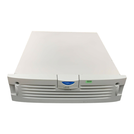
38 Chapter 2 Nortel VPN Router 1750 chassis The following figure shows the front view of the Nortel VPN Router 1750. Figure 14 Front view of the Nortel VPN Router 1750 Alert Boot/Ready CS260001D The VPN Router 1750 chassis provides the following physical features: •... -
Page 39: Shipment Contents
Records the IP address (apply to front bezel) Inspect all items for shipping damage. If you detect damage, do not install the VPN Router 1750. Call the Nortel Technical Solutions Center in your area. Nortel VPN Router Installation — VPN Router 1750... -
Page 40: Additional Equipment
Before you begin the installation, ensure that you have all the cables, tools, and other equipment that you need. Cables You need cables that do not ship in the VPN Router 1750 shipping container. For more information about which cables ship and which ones you can order, see “Connecting communications cables” on page 22. -
Page 41: Chassis Installation
“Installing the chassis in an equipment rack” on page Installing the chassis on a flat surface If you decide to place the VPN Router 1750 on a flat surface, make sure that the surface is large enough for the gateway, and sturdy enough to support the combined weight of the VPN Router 1750 and the cables that you attach to it. -
Page 42: Installing The Chassis In An Equipment Rack
Attaching the shelf in the equipment rack The VPN Router 1750 ships with a rack-mount shelf to support the chassis in the equipment rack. To attach the shelf to the inside of the equipment rack, perform the following steps: NN46110-316 03.01... - Page 43 Chapter 2 Nortel VPN Router 1750 chassis 43 Attach a cage nut in four locations at the front of the rack, if the holes in the vertical supports of the rack are not threaded. Rail without threaded holes Cage nut...
- Page 44 To install the VPN Router 1750 in the equipment rack, perform the following steps: Set the VPN Router 1750 on the rack-mount shelf. Remove the front bezel from the VPN Router 1750 as shown in the following figure. CS260015E Use the Phillips screwdriver to turn each of the two screws on the front bezel a quarter turn counterclockwise.
- Page 45 Chapter 2 Nortel VPN Router 1750 chassis 45 Replace the front bezel as shown in the following figure. Press here CS260005E Hold the two handles on the bezel, and push it onto the chassis. Use the Phillips screwdriver to tighten the two screws that secure the bezel to the chassis.
- Page 46 46 Chapter 2 Nortel VPN Router 1750 chassis NN46110-316 03.01 Get other manuals https://www.bkmanuals.com...
-
Page 47: Option Card And Dimm Installation
Chapter 3 Option card and DIMM installation This chapter provides instructions about how to install and replace the following field replaceable units (FRU) in the VPN Router 1750: • Local Area Network (LAN), Wide Area Network (WAN), and serial interface cards •... -
Page 48: Shutting Down The System To Add Or Replace Hardware
Nortel VPN Router 1750” on page 23). Warning: Risk of electric shock Make sure to turn off the VPN Router 1750 and unplug the power cord before you attempt to remove or install an option card or DIMM. NN46110-316 03.01... -
Page 49: Removing The Front Bezel And Top Cover
To remove the front bezel, perform the following steps: Shut down the VPN Router 1750 using the Web GUI or the CLI, and then unplug it as described in “Shutting down the system to add or replace hardware”... - Page 50 At the front of the chassis, remove the two panhead screws that secure the bottom of the chassis to the equipment rack. Remove the VPN Router 1750 from the rack-mount shelf, and then set the router on a sturdy surface.
- Page 51 Lift the lid 2 or 3 inches, and then pull it off the chassis. The VPN Router 1750 system board is now exposed. The following figure shows the location of the option card and DIMM slots on the system board.
-
Page 52: Attaching The Antistatic Wrist Strap
52 Chapter 3 Option card and DIMM installation Attaching the antistatic wrist strap Nortel ships the VPN Router 1750 with an antistatic wrist strap, which directs the discharge of static electricity from your body to the chassis of the gateway to avoid damage to sensitive electronic components. -
Page 53: Option Card Installation And Replacement
Option card installation and replacement The VPN Router 1750 provides four slots for option cards. This section provides instructions about how you can add new option cards to the VPN Router 1750 or, if necessary, replace an existing card. The following table lists the option cards that you can install in the VPN Router 1750. -
Page 54: Installing The Ssl Vpn Module 1000 With Other Option Cards
Version 4.76 or later, or the hardware revision must be at least 03. Installing the SSL VPN Module 1000 with other option cards If you install an SSL VPN Module 1000 in the VPN Router 1750, the following restrictions on other option cards apply: •... -
Page 55: Installing And Replacing An Option Card
Before you install or replace an interface card or Hardware Accelerator card, complete the following procedures: • Shut down the VPN Router 1750 by using the Web GUI or the CLI, and then unplug it as described in “Shutting down the system to add or replace hardware”... - Page 56 56 Chapter 3 Option card and DIMM installation Remove the filler panel screw, and pull out the filler panel (or the option card to replace) from the slot as shown in the following figure. Rear of unit Filler panel screw Option card Motherboard Option card slots...
-
Page 57: Installing And Replacing Dimms
Chapter 3 Option card and DIMM installation 57 If you want to install the VPN Router 1750 in an equipment rack, mount it in the rack. Set the VPN Router 1750 on the rack-mount shelf in the rack. 10 Insert one of the panhead screws through the bottom hole on each side of the shelf into the hole in the rack, and tighten the screws. - Page 58 Before you install or replace a DIMM, complete the following procedures: • Shut down the VPN Router 1750 by using the Web GUI or the CLI, and then unplug it as described in “Shutting down the system to add or replace hardware”...
- Page 59 Alignment keys To remove DIMMs, pull back locking levers and pull out DIMM. To install DIMMs, pull back locking levers and push in DIMM. Locking lever CS260019A Nortel VPN Router Installation — VPN Router 1750 Get other manuals https://www.bkmanuals.com...
- Page 60 Insert the four screws that secure the cover to the chassis, and use a screwdriver to tighten the screws. If you want to install the VPN Router 1750 in an equipment rack, mount it in the rack. 10 Set the VPN Router 1750 on the rack-mount shelf in the rack.
-
Page 61: Management Ip Interface Configuration
VPN Router 1750. After you complete the procedures in this chapter, you can configure and manage the VPN Router 1750 by using a Web browser from a PC. To configure the management IP interface, you can use the serial interface configuration menu. -
Page 62: Required Information
IP address for the management interface The management IP address must be accessible from one of the private physical interfaces on the VPN Router 1750. For example, if you plan to assign IP address 10.2.3.3 with subnet mask 255.255.0.0 to the private physical interface, the management IP address must reside in the 10.2... -
Page 63: Configuring The Management Ip Address
Chapter 4 Management IP interface configuration 63 Configuring the management IP address Use the serial interface to assign the VPN Router 1750 a management IP address and subnet mask so that you can then use a Web browser for management. - Page 64 64 Chapter 4 Management IP interface configuration The serial main menu appears with the following message. Main Menu: System is currently in NORMAL mode. 0) Management Address 1) Interfaces 2) Administrator 3) Default Private Route Menu 4) Default Public Route Menu 5) Create A User Control Tunnel (IPsec) Profile 6) Restricted Management Mode FALSE...
- Page 65 1) Slot 0, Port 1, Private LAN IP Address =192.167.120.14 Subnet Mask = 255.255.255.0 Speed/Duplex = AutoNegotiate R) Return to the Main Menu. Please select a menu choice: Nortel VPN Router Installation — VPN Router 1750 Get other manuals https://www.bkmanuals.com...
- Page 66 16 From the serial main menu, type E, and then press Enter to save the new management IP address and mask, and to exit the serial menu. For more information about how to configure and manage the VPN Router 1750, see the documentation on the VPN Router software CD.
-
Page 67: Testing The Configuration
After you assign a management IP address to the VPN Router 1750, start a Web browser to verify that you can access the gateway from a browser. To manage the VPN Router 1750 by using the GUI, your PC must run one of the following browsers: •... -
Page 68: Troubleshooting
Check the physical connections on the VPN Router 1750, especially the LAN cables and the power cord. If you still cannot connect to the VPN Router 1750 by using a browser, connect a terminal or PC to the gateway with the serial cable and check the management IP address listed in the serial menu. -
Page 69: Technical Specifications
Appendix A Technical specifications This appendix provides technical specifications for the VPN Router 1750 chassis and the chassis interfaces. Chassis specifications The following table lists physical, electrical, and environmental specifications for the chassis. Table 17 Physical, electrical, and environmental specifications... -
Page 70: System Ports
5 twisted-pair Ethernet wiring: one pair each for transmit and receive operations. Nortel recommends that you use a maximum length of 100 meters for the cable segment between a 100BASE-TX repeater and a workstation (due to signal timing requirements). This wiring scheme complies with the EIA 568 wiring standard. -
Page 71: Serial Port
DB9 or DB25 connector connects to the workstation. “Modem cable (9-pin D-sub plug to RS-232-C modem plug)” on page 72 shows the serial cable ends. Nortel VPN Router Installation — VPN Router 1750 Get other manuals https://www.bkmanuals.com... -
Page 72: Modem Cable Specifications
> Modem cable specifications If you need to connect a modem to a VPN Router 1750, you must obtain an appropriate modem cable. The modem cable must have a 9-pin D-sub plug that connects to the VPN Router 1750 serial port and a 25-pin D-sub plug that connects to the RS-232-C modem port. -
Page 73: Hardware Option Cards
This section provides information about the option cards, including the connector and the cable pinouts for each supported network interface card. The VPN Router 1750 provides four peripheral component interconnect (PCI) slots that support a combination of the following option cards: •... -
Page 74: Vpn Router Security Accelerator Card
High Speed Serial Interface (HSSI) WAN interface card VPN Router Security Accelerator card Nortel supports the VPN Router Security Accelerator option card that performs bulk encryption and compression algorithms for IPsec tunnel traffic. The VPN Router Security Accelerator card uses a single Hifn 7854 chip for encryption and compression and has 64 MB of onboard RAM. -
Page 75: Ssl Vpn Module 1000
The VPN Router Security Accelerator card is the successor to the Hardware Accelerator card. Even though Nortel discontinued the Hardware Accelerator Hifn 7811 card effective January 2006, Nortel still supports this card. The VPN Router Security Accelerator card provides increased encryption throughput and improved compression performance. - Page 76 SSL VPN Module 1000 provides and immediately forwards the appropriate traffic to the SSL VPN module. Note: For more information about the SSL VPN Module 1000 and instructions to configure it, see Nortel VPN Router Configuration — SSL VPN Services (NN46110-501). NN46110-316 03.01...
-
Page 77: 10/100Base-Tx Ethernet Interface Card
7.05.100 and all subsequent versions (FIPS branch) • 7.05.300 and all subsequent versions The 1000 GT card does not replace the high-performance 1000BASE-T 1000 MT card (see the following section). Nortel VPN Router Installation — VPN Router 1750 Get other manuals https://www.bkmanuals.com... - Page 78 • For 1000BASE-T operation, use category 5 four-pair Ethernet wiring. The cable must comply with the TIA 568 wiring specification. Nortel recommends a maximum length of 100 meters for the cable segment. •...
-
Page 79: 1000Base-T (1000 Mt) Ethernet Interface Card
Select cables for this port as follows: • For 1000BASE-T operation, use category 5 four-pair Ethernet wiring. The cable must comply with the TIA 568 wiring specification. Nortel recommends a maximum length of 100 meters for the cable segment. •... - Page 80 80 Appendix A Technical specifications Table 22 1000BASE-T (1000 MT) Ethernet port pinouts Description TP3+ TP3- NN46110-316 03.01 Get other manuals https://www.bkmanuals.com...
-
Page 81: 1000Base-Sx Ethernet Interface Card
50-micron MMF cable: provides a distance range of 500–550 meters (m) • 62.5-micron MMF cable: provides a distance range of 220–275 m You can order a 10-foot MMF cable from Nortel: • Order no. DM0011117 provides an LC-to-LC connector •... -
Page 82: 56/64K Csu/Dsu Wan Interface Card
Use cable that is wired in accordance with ANSI T1.410 wiring style. This wiring style ensures that a twisted pair inside the patch cord carries the transmit signal (pins 1 and 2) and the receive signal (pins 7 and 8). Nortel strongly recommends that you use professionally manufactured patch cords. - Page 83 Transmit ring Transmit ring Not used Not used Not used Not used Not used Not used Not used Not used Receive tip Receive tip Receive ring Receive ring Nortel VPN Router Installation — VPN Router 1750 Get other manuals https://www.bkmanuals.com...
-
Page 84: Adsl Wan Interface Card
84 Appendix A Technical specifications ADSL WAN interface card The ADSL Annex A and Annex B WAN interface cards have a single RJ-11 connector that provides the signals needed to interface to the ADSL-provisioned telephone line. “ADSL WAN interface card” on page 84 shows the ADSL WAN interface card. -
Page 85: Isdn Bri Interface Card
8-pin RJ-45 modular patch cord. These cables are sold as category 5, or Ethernet, cables. Note: Nortel does not supply a cable with the ISDN BRI interface cards. Nortel VPN Router Installation — VPN Router 1750 Get other manuals https://www.bkmanuals.com... - Page 86 86 Appendix A Technical specifications The following table provides the ISDN BRI S/T cable pinouts. Table 27 ISDN BRI S/T cable pinouts Function Receive + Transmit + Transmit - Receive - The following table provides the ISDN BRI U cable pinouts. Table 28 ISDN BRI U cable pinouts Function U interface network connection (tip)
-
Page 87: T1/E1 Csu/Dsu Wan Interface Card
The connector on the T1/E1 CSU/DSU WAN interface accommodates an 8-pin RJ-48 modular patch cord. These cables are commonly sold as category 5, or Ethernet, cables. Note: Nortel does not supply the T1/E1 CSU/DSU WAN interface cable with the WAN interface card. Nortel VPN Router Installation — VPN Router 1750... - Page 88 Use cable that is wired in accordance with EIA-568-A wiring style. This wiring style ensures that a twisted pair inside the patch cord carries the transmit signal (pins 4 and 5) and the receive signal (pins 1 and 2). Nortel strongly recommends that you use professionally manufactured patch cords.
-
Page 89: Quad T1/E1 Csu/Dsu Wan Interface Card
Each connector on the quad T1/E1 CSU/DSU WAN interface card accommodates an 8-pin RJ-48 modular patch cord. These cables are commonly sold as category 5, or Ethernet, cables. Note: Nortel does not supply cables with the quad T1/E1 CSU/DSU interface card. Nortel VPN Router Installation — VPN Router 1750... -
Page 90: V.90 Modem Interface Card
Use cable that is wired in accordance with EIA-568-A wiring style. This wiring style ensures that a twisted pair inside the patch cord carries the transmit signal (pins 4 and 5) and the receive signal (pins 1 and 2). nortel strongly recommends that you use professionally manufactured patch cords. -
Page 91: Single V.35/X.21 Wan Interface Card
Table 32 V.35 cable pinouts Special- Standard-wired Pair number wired end end 28-pin male Signal name and conductor 34-pin male Notes TXDA Pair 1A TXDB Pair 1B Nortel VPN Router Installation — VPN Router 1750 Get other manuals https://www.bkmanuals.com... - Page 92 92 Appendix A Technical specifications Table 32 V.35 cable pinouts (continued) Special- Standard-wired Pair number wired end end 28-pin male Signal name and conductor 34-pin male Notes RXDA Pair 2A RXDB Pair 2B TXCA Pair 3A TXCB Pair 3B RXCA Pair 4A RXCB Pair 4B...
- Page 93 SIGNAL GROUND Pair 14B Wires 12B, 13A, and 14B connect to pin B in the 34-pin connector. Do not connect Shield to Signal Ground because these are separate signals. Nortel VPN Router Installation — VPN Router 1750 Get other manuals https://www.bkmanuals.com...
- Page 94 94 Appendix A Technical specifications The following table provides the X.21 cable pinouts. (The pair suffix A or B refers to an individual wire within a twisted pair.) Table 33 X.21 cable pinouts Standard- Standard- wired end Pair number wired end 28-pin male Signal name and conductor 15-pin male...
- Page 95 15-pin connector. M2<-SIGNAL GROUND Pair 13B Wires 13B and 14B connect to pin 8 in the 15-pin connector. Nortel VPN Router Installation — VPN Router 1750 Get other manuals https://www.bkmanuals.com...
-
Page 96: Hssi Wan Interface Card
96 Appendix A Technical specifications Table 33 X.21 cable pinouts (continued) Standard- Standard- wired end Pair number wired end 28-pin male Signal name and conductor 15-pin male Notes SHIELD Pair 14A At each end, the cable shield and connector shell must connect to pin 1 of the connector. - Page 97 Appendix A Technical specifications 97 Table 34 T3 cable pinouts (continued) 50-pin SCSI male Signal name 50-pin SCSI male TESTB TESTA Nortel VPN Router Installation — VPN Router 1750 Get other manuals https://www.bkmanuals.com...
- Page 98 98 Appendix A Technical specifications NN46110-316 03.01 Get other manuals https://www.bkmanuals.com...
-
Page 99: Index
56/64K CSU/DSU WAN interface card cables cable pinouts 83, 85 available from Nortel 22 connector 82 connecting to the gateway 23 described 82 ordering 22 installing 53 power. See AC power cord Nortel VPN Router Installation — VPN Router 1750 Get other manuals https://www.bkmanuals.com... - Page 100 100 Index technical specifications ISDN BRI S/T interface 85 1000BASE-SX connector 81 quad T1/E1 CSU/DSU WAN interface 89 1000BASE-T (1000 MT) connector 79 single V.35/X.21 WAN interface 91 100BASE-TX connector 70 T1/E1 CSU/DSU WAN interface 87 10BASE-T connector 70 V.90 modem interface 90 56/64K CSU/DSU WAN interface 82 cover, top ADSL WAN interface 84...
- Page 101 SSL VPN Module 1000 36 interfaces, system, technical specifications 70 system LAN port 27 T1/E1 CSU/DSU WAN interface card 33 Internet Explorer, supported versions 67 used to verify correct installation 25 Nortel VPN Router Installation — VPN Router 1750 Get other manuals https://www.bkmanuals.com...
- Page 102 102 Index single V.35 WAN interface 91 single X.21 WAN interface 94 main menu, serial interface 64 T1/E1 CSU/DSU WAN interface 88 management IP address V.90 modem interface 91 configuring 63 plug, AC power, specifications 24 defined 62 power cord troubleshooting configuration of 68 connecting 24 verifying 67...
- Page 103 87 VPN Router Security Accelerator card installing 53 described 74 LEDs 33 installing 53 T3 HSSI WAN interface card. See HSSI WAN interface card technical publications 15 Nortel VPN Router Installation — VPN Router 1750 Get other manuals https://www.bkmanuals.com...
- Page 104 104 Index WAN interface cards installing 53 LEDs 56/64K CSU/DSU 31 ADSL 32 quad T1/E1 CSU/DSU 34 single V.35/X.21 35 T1/E1 CSU/DSU 33 specifications 56/64K CSU/DSU 82 ADSL 84 HSSI 96 quad T1/E1 CSU/DSU 89 single V.35/X.21 91 T1/E1 CSU/DSU 87 Web interface to the gateway 67 wiring requirements, Category 5 70, 78, 79 wrist strap, antistatic, attaching 52...
Need help?
Do you have a question about the VPN Router 1750 and is the answer not in the manual?
Questions and answers