
Related Manuals for GoMax Electronics SP-1014


Summary of Contents for GoMax Electronics SP-1014
- Page 1 1x4 DVI Splitter over Single Cat.X with HDCP Support User Manual rev: 111209 Made in Taiwan...
-
Page 2: Table Of Contents
However, like all electronic equipments, the SP-1014 should be used with care. Please read and follow the safety instructions to protect yourself from possible injury and to minimize the risk of damage to the unit. -
Page 3: Introduction
The length depends on the characteristics and quality of the cables. Higher resolutions and longer transmission distances require low skew cables (<25ns/100m) for best performance. Unshielded CAT6 with metal RJ45 connectors is recommended. PACKAGE CONTENTS ● 1x SP-1014 ● 1x DC 5V 4A in-line with C7 power cord ● 1x User Manual... -
Page 4: Specifications
SPECIFICATIONS Model Name SP-1014 Technical SP-1014[TX] CV-17[RX] CV-117[RX] 1x4 Distribution Amplifier Receiver Receiver Role of usage Transmitter [TX] [long range RX] [short range RX] DVI compliance DVI 1.1 HDCP compliance Video bandwidth Single-link 165MHz [4.95Gbps] Video support Up to (Single) WUXGA 1920 × 1200 @ 60 Hz... -
Page 5: Panel Descriptions
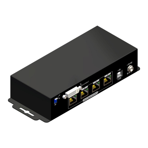
PANEL DESCRIPTIONS Front Panel Power indicator LED Rear Panel DIP SWITCH: see more detail in the next page DVI-D INPUT: connect to one DVI source here DVI-D Signal OUTPUT 1~4: link to each DVI display via a Cat-5/5e/6 cable with a DVI over Cat.X receiver CV-711 or CV-711S. -
Page 6: Hardware Installation
HARDWARE INSTALLATION Broadcasts DVI signals to 4 remote displays from one video source 1. Switch off all devices, including displays. 2. Connect the DVI source to the DVI-D INPUT port. 3. Connect the receivers (CV-711 or CV-711S) via solid Cat-5/5e/6 cables to each DVI-D Signal OUTPUT port. -
Page 7: Dip Switch
DIP SWITCH DIP Switch Position EDID Mode Description Pin#1 Pin#2 1 – EDID preferred timing is 1920x1080 OFF [] OFF [] Up to 1920x1080 Default Mode – EDID preferred timing is 1024x768 ON [ ] OFF [] Up to 1024x768 Default Safe Mode 2 –... -
Page 8: Pin Definition
PIN DEFINITION A female DVI-I socket from the front Pin 1 TMDS Data 2- Pin 10 TMDS Data 1+ Pin 18 TMDS data 0+ Pin 2 TMDS Data 2+ Pin 11 TMDS Data 1/3 shield Pin 19 TMDS data 0/5 shield Pin 3 TMDS Data 2/4 shield Pin 12... -
Page 9: Notice
NOTICE 1. If the DVI device requires the EDID information, please use EDID Reader/Writer to retrieve and provide DVI display EDID information. 2. All DVI over Cat.X transmission distances are measured using Belden 1583A CAT5e 125MHz UTP cable and ASTRODESIGN Video Signal Generator VG-859C. 3. -
Page 10: Warranty
SELLER will NOT be liable for direct, indirect, incidental, special, or consequential damages resulting from any defect or omission in this manual, even if advised of the possibility of such damages. Also, the technical information contained herein regarding the SP-1014 features and specifications is subject to change without further notice.
Need help?
Do you have a question about the SP-1014 and is the answer not in the manual?
Questions and answers