Table of Contents
Advertisement
Available languages
Available languages
ENGLISH
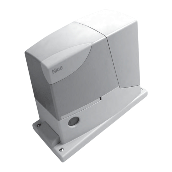
This Addendum states the specific data of the product RD300. For all other sub-
jects, refer to the manual of the product Road200
Operating limits: in general, RD300 is suitable for the automation of gates
featuring leaves up to 6 m wide and weighing up to 300 kg, as shown in Tables
1 and 2. The length of the leaf makes it possible to determine both the maximum
number of cycles per hour and consecutive cycles, while the weight makes it
possible to determine the reduction percentage of the cycles and the maximum
speed allowed.
TABLE 1 - Limits in relation to the length of the leaf
Leave width m
Max cycle/hour
Up to 3
3 - 5
5 - 6
TABLE 2 - Limits in relation to the weight of the leaf
Leaf weight Kg
Up to 200
200÷300
TECHNICAL SPECIFICATIONS:
Peak thrust
9 Nm; corresponds to the ability to start a leaf with a
static friction of max. 300 N moving
Nominal torque
4 Nm; corresponds to the ability to keep a leaf with a
dynamic friction of max. 135 N moving
Idling speed
0.25 m/s; the control unit allows 2 speeds to be pro
grammed, equal to: 0.13 m/s or 0.25 m/s
Nominal torque speed
0,16 m/s
Maximum frequency of
50 cycles per day (the control unit allows up to the
operating cycles
maximum described in tables 1 and 2)
Maximum continuous operating
time 9 minutes (the control unit limits the continuous
operation up to the maximum described in tables 1
and 2)
Max. absorbed power
210 W (1,1 A)
ITALIANO
Il presente Addendum riporta i dati specifici del prodotto RD300. Per tutti gli altri
argomenti fare riferimento al manuale del prodotto Road200.
Limiti d'impiego: generalmente RD300 è in grado di automatizzare cancelli
con peso fino a 300 Kg oppure lunghezza fino a 6 m secondo quanto riportato
nelle tabelle 1 e 2. La lunghezza dell'anta permette di determinare il numero
massimo di cicli per ora e di cicli consecutivi mentre il peso permette di deter-
minare la percentuale di riduzione dei cicli e la velocità massima consentita.
TABELLA 1 - Limiti in relazione alla lunghezza dell'anta
Lunghezza anta metri
Cicli/ora massimi
Fino a 3
3 - 5
5 - 6
TABELLA 2- Limiti in relazione al peso dell'anta
Peso anta Kg
Fino a 200
200÷300
CARATTERISTICHE TECNICHE SPECIFICHE:
Coppia massima allo spunto
9 Nm; corrispondente alla capacità di mettere in
movimento un'anta con attrito statico fino a 300 N
Coppia nominale
4 Nm; corrispondente alla capacità mantenere in
movimento un'anta con attrito dinamico fino a 135 N
Velocità a vuoto
0.25 m/s; la centrale consente di programmare 2
velocità, pari a: 0,13 m/s o 0,25 m/s
Velocità alla coppia nominale
0,16 m/s
Frequenza massima cicli di
50 cicli/giorno (la centrale limita i cicli al massimo
funzionamento
previsto nelle tabelle 1 e 2)
Tempo massimo funzionamento
9 minuti (la centrale limita il funzionamento continuo
al massimo previsto nelle tabelle continuo
Potenza massima assorbita
210 W (1,1 A)
Max. no. of
consecutive cycles
25
17
15
10
12
8
% cycles
100%
85%
Cicli consecutivi massimi
25
17
15
10
12
8
Percentuale cicli
100%
85%
RD300
For sliding gates
EN -
Integration to manual ROAD200
IT -
Integrazione al manuale ROAD200
FR -
Addenda au guide ROAD200
ES -
Integración del manual ROAD200
DICHIARAZIONE CE DI CONFORMITÀ / CE DECLARATION OF CONFORMITY
Nota - Il contenuto di questa dichiarazione corrisponde a quanto dichiarato nell'ultima revisione disponibile, prima della stampa di que-
sto manuale, del documento ufficiale depositato presso la sede di Nice Spa. Il presente testo è stato riadattato per motivi editoriali. /
Note - The contents of this declaration correspond to those of the last revision available of the official document, deposited at the regis-
tered offices of Nice S.p.a., before printing of this manual. The text herein has been re-edited for editorial purposes.
Numero / Number: 318/RD300
Il sottoscritto Luigi Paro in qualità di Amministratore Delegato, dichiara sotto la propria responsabilità che il prodotto: / The
undersigned Luigi Paro, managing director, declares under his sole responsibility that the following product:
Nome produttore / Manufacturer's name: NICE s.p.a.
Indirizzo / Address: Via Pezza Alta 13, 31046 Z.I. Rustignè, Oderzo (TV) Italia / Italy
Tipo / Type: Motoriduttore elettromeccanico "RD300" con centrale incorporata / "RD300" ac electromechanical gearmotor
with built-in control unit
Modello / Models: RD300
Risulta conforme a quanto previsto dalla direttiva comunitaria: / Satisfies the essential requirements of the following Directives:
• 98/37/CE (89/392/CEE modificata) / 98/37/EC (89/392/EEC amended).
Come previsto dalla direttiva 98/37/CE si avverte che non è consentita la messa in servizio del prodotto sopra indicato fin-
ché la macchina, in cui il prodotto è incorporato, non sia stata identificata e dichiarata conforme alla direttiva 98/37/CE /
As specified in the directive 98/37/CEE use of the product specified above is not admitted until the machine on which it is
mounted has been identified and declared as conforming to the directive 98/37/CEE.
Inoltre risulta conforme ai requisiti essenziali richiesti dall'articolo 3 dalla seguente direttiva comunitaria, per l'uso al quale i
prodotti sono destinati: / Furthermore, the product complies with the essential requisites specified in article 3 of the follow-
ing EC directive, for the use the products have been manufactured for:
• 1999/5/CE DIRETTIVA / 1999/5/CE DIRECTIVE
Secondo le seguenti norme armonizzate / According to the following harmonised standards
protezione della salute / health protection: EN 50371:2002; sicurezza elettrica / electrical safety: EN 60950-1:2006;
compatibilità elettromagnetica / electromagnetic compatibility: EN 301 489-1V1.8.1:2008; EN 301 489-3V1.4.1:2002
spettro radio / radio range: EN 300220-2V2.1.2:2007
Inoltre il prodotto risulta conforme a quanto previsto dalle seguenti direttive comunitarie: / Furthermore, the product com-
plies with the specifications of the following EC directives:
• 2006/95/CEE(ex direttiva 73/23/CE) / 2006/95CE(ex directive 73/23/CE)
Secondo la seguente norma armonizzata: / According to the following harmonised standards:
EN 60335-1:1994+A11:1995+A1:1996+A12:1996+A13:1998+A14:1998+A15:2000+A2:2000+A16:2001
• 2004/108/CEE(ex direttiva 89/336/CEE) / 2004/108/CEE(ex directive 89/336/CEE)
Secondo le seguenti norme armonizzate: / According to the following harmonised standards: EN 61000-6-2:2005; EN
61000-6-3:2007
Inoltre risulta conforme, limitatamente per le parti applicabili, alle seguenti norme: / Furthermore, complies with the speci-
fications, limitedly for the applicable the following standards: EN 60335-1:2002+A1:2004+A11:2004+A12:2006+ A2:2006,
EN 60335-2-103:2003, EN 13241-1:2003; EN 12453:2002; EN 12445:2002; EN 12978:2003
Oderzo, 14 aprile 2009 / Oderzo, 14 april 2009
FRANÇAIS
Cet addenda contient des données spécifiques au produit RD300. Pour tous les
autres points, se référer au guide d'instructions du produit Road200
Limites d'utilisation : généralement ROAD300 est en mesure d'automatiser
des portails pesant jusqu'à 300 kg ou mesurant jusqu'à 6 m suivant les indica-
tions des tableaux 1 et 2. La longueur du portail permet de calculer le nombre
maximum de cycles à l'heure et de cycles consécutifs tandis que le poids per-
met de calculer le pourcentage de réduction des cycles et la vitesse maximum
admissible.
TABLEAU 1- Limites suivant la longueur du portail
Longueur du portail
en mètres
Jusqu'à 3
3 - 5
5 - 6
TABLEAU 2 - Limites suivant le poids du portail
Poids portail en kg
Jusqu'à 200
200÷300
CARACTÉRISTIQUES TECHNIQUES SPÉCIFIQUES:
Couple maximum au démarrage
Couple nominal
Vitesse à vide
Vitesse a couple nominal
Fréquence maximum des cycles
de fonctionnement
Temps maximum de
fonctionnement continu
Puissance maximum absorbée
DE -
Vervollständigung des Handbuchs
ROAD200
PL -
Uzupełnienie do instrukcji
ROAD200
NL -
Aanvulling op de
handleiding ROAD200
Revisione / Revision: 0
Accessori / Accessories:
Luigi Paro
(Amministratore Delegato / Managing Director)
Cycles/heure
Cycles consécutifs
maximums
maximums
25
17
15
10
12
8
Pourcentage cycles
100%
85%
9 Nm ; correspondant à la capacité de mettre en
mouvement un portail avec friction statique jusqu'à
300 N
4 Nm ; correspond à la capacité de maintenir en
mouvement un portail avec friction dynamique
jusqu'à 135
0.25 m/s ; la logique de commande permet de pro
grammer 2 vitesses, égales à: 0.13 m/s ou à 0.25 m/s
0,16 m/s
50 cycles/jour (la logique limite les cycles au maximum
prévu dans les tableaux 1 et 2)
de 9 minutes (la logique limite le fonctionnement
continu au maximum prévu dans les tableaux 1 et 2)
210 W (1,1 A)
Advertisement
Chapters
Table of Contents

Related Manuals for Nice Road200


Summary of Contents for Nice Road200
- Page 1 Nota - Il contenuto di questa dichiarazione corrisponde a quanto dichiarato nell’ultima revisione disponibile, prima della stampa di que- sto manuale, del documento ufficiale depositato presso la sede di Nice Spa. Il presente testo è stato riadattato per motivi editoriali. / Up to 3 Note - The contents of this declaration correspond to those of the last revision available of the official document, deposited at the regis-...
- Page 2 En el presente Addendum se indican los datos específicos del producto RD300. Dieses Addendum führt die spezifischen Daten des Produkts RD300 auf. Alle Para los demás argumentos, consulte el manual del producto. anderen Themen können im Handbuch des Produkts Road200 nachgesehen werden. Límites de utilización: generalmente, RD300 es adecuado para automatizar puertas de hasta 300 kg de peso o de hasta 6 m de largo, según las indicacio-...
-
Page 3: Warnings 3
For sliding gates Road200 Instructions and warnings for the fitter Istruzioni ed avvertenze per l’installatore Instructions et recommandations pour l’installateur Anweisungen und Hinweise für den Installateur Instrucciones y advertencias para el instalador Instrukcje i uwagi dla instalatora Aanwijzingen en aanbevelingen voor de installateur... -
Page 4: Table Of Contents
Road200 Table of contents: page Warnings Additional information Programming buttons Product description and applications Programming Operating limits 7.2.1 Level one functions (ON-OFF functions) Typical system 7.2.2 Level one programming List of cables (ON-OFF functions) 7.2.3 Level two functions Installation (adjustable parameters) Preliminary checks 7.2.4... -
Page 5: Warnings
“WARNING: MAINTENANCE WORK IN • Any use or operation of ROAD200 which is not explicitly provided for in PROGRESS”. these instructions is not permitted. Improper use may cause damage and personal injury. -
Page 6: List Of Cables
Chapter 8 “Technical Characteristics” provides the data needed to determine whether ROAD200 components are suitable for the intended application. In general, ROAD200 is suitable for the automation of gates featuring leaves up to 5 m wide and weighing up to 200 kg, as shown in Tables 1 and 2. -
Page 7: Installation
3) Installation The installation of ROAD200 must be carried out by qualified personnel in compliance with current legislation, standards and regulations, and the directions provided in this manual. 3.1) Preliminary checks Before proceeding with the installation of ROAD200 you must: •... -
Page 8: Installation Of The Various Devices
If the rack is already present, once the gearmotor has been fastened, use the adjustment dowels as shown in Figure 8 to set the pinion of ROAD200 to the right height, leaving 1÷2 mm of play from the rack. Otherwise, in order to fasten the rack the installer must: 6. -
Page 9: Electrical Connections
1. Remove the protection cover in order to access the electronic figure 13, then block the cable at the first cable block ring using control unit of the ROAD200. The side screw must be removed, the clamp. and the cover lifted upwards. -
Page 10: Description Of The Electrical Connections
7 - 8 Flashing light a NICE “LUCY B” flashing light with a 12V 21W car bulb can be connected to this output. During the manoeuvre the unit flashes at intervals of 0.5 s 4) Final checks and start up... -
Page 11: Recognizing The Length Of The Leaf
1. Press the [PP] button to open the gate. Check that gate open- 5. Check that the fastening of the ROAD200 gearmotor, the rack ing occurs regularly, without any variations in speed. The leaf and the limit switch brackets are solid, stable and suitably resis- must only slowdown and stop when it is between 50 and 30 cm tant, even if the gate accelerates or decelerates sharply. -
Page 12: Memorization Of Radio Transmitters
4.7) Memorization of radio transmitters Each radio transmitter is recognised by the said receiver by means of a “code” which is different from that of any other transmitter. A “mem- orisation” phase must therefore be performed in order to allow the receiver to recognise each single transmitter. Transmitters can be mem- orised in 2 modes: Table 5: Memorization Mode I Mode I: in this mode the function of the transmitter buttons is fixed... -
Page 13: Remote" Memorization
To test ROAD200 proceed as follows: 5. If the dangerous situations caused by the movement of the leaf 1. Ensure that the instructions outlined in this manual and in partic- have been safeguarded by limiting the force of impact, the user ular in chapter 1 "WARNINGS"... -
Page 14: Commissioning
7) Additional information Programming, personalisation and how to look for and deal with faults on the ROAD200 will be dealt with in this chapter. 7.1) Programming buttons The ROAD200 control unit feature three buttons that can be used to command the control unit both during tests and programming. -
Page 15: Programming
If the function is inactive, functioning will be “semi-automatic”. During the normal functioning of ROAD200, LEDs L2 and L3 will either be on or off depending on the state of the function they represent. For example, L3 will be on if the “Automatic Closing” function is active. -
Page 16: Level Two Programming
7.2.4) Level two programming (adjustable parameters) The adjustable parameters are factory set as shown in table 15, with: “ “. However, they can be changed at any time as shown in Table 16. Follow the procedure carefully, as there is a maximum time of 10 seconds between pressing one button and another. If a longer period of time lapses, the procedure will finish automatically and memorize the modifications made up to that stage. -
Page 17: Level Two Programming Example
Wait 10 seconds before leaving the programme to allow the maximum time to lapse. 7.3) Adding or removing devices Devices can be added to or removed from the ROAD200 automa- tion system at any time. In particular, various devices types can be connected to “STOP”... -
Page 18: Photocells
7.3.2) Photocells The ROAD200 control unit is equipped with the “Phototest” function Whereas, if the test has a negative outcome (photocell blinded by the which increases the reliability of the safety devices, making it possible sun, short circuited cable etc), the fault is identified and the manoeu- to achieve "category 2"... -
Page 19: Troubleshooting
No manoeuvre starts and the OK LED does Check that ROAD200 is powered by a 230V mains supply. Check to see if the fuses F1 not flash and F2 are blown; if necessary, identify the reason for the failure and then replace the fuses with others having the same current rating and characteristics. -
Page 20: Signals On The Control Unit
7.7.2) Signals on the control unit On the ROAD200 control unit there is a set of LED each of which can give special indications both during normal operation and in case of malfunctions. Table 21: LED's on the control unit's terminals... -
Page 21: Technical Characteristics
8) Technical characteristics Nice S.p.a., in order to improve its products, reserves the right to modify their technical characteristics at any time without prior notice. In any case, the manufacturer guarantees their functionality and fitness for the intended purposes. All the technical characteristics refer to a room temperature of 20°C (±5°C). - Page 22 Technical characteristics: transmitter: FLO2 transmitter: FLO2R-S transmitter: SM2 Type 2 channel transmitter for radio command Frequency 433.92MHz Coding Digital fixed code with Digital Rolling code Digital Rolling code with 12 Bit code, FLO type with 52 Bit code, FLOR type 64 Bit code, SMILO type buttons Power supply...
-
Page 23: Instructions And Warnings For Users Of Road Gearmotor
This operation movement if people or objects are in the way, guar- has been carefully designed by Nice to make it anteeing safe and reliable activation. However, chil- extremely easy, without any need for tools or physi- dren should not be allowed to play in the vicinity of cal exertion. - Page 24 Are you satisfied? If you wish to install another automation system in your home, call your old installation technician and use Nice products. You will get the services of a specialist and the most advanced products available on the mar- ket, superior performances and maximum system compatibility.
- Page 26 Road200 Indice: pag. Avvertenze Approfondimenti Tasti di programmazione Descrizione prodotto e destinazione d’uso Programmazioni Limiti d’impiego 7.2.1 Funzioni primo livello (funzioni ON-OFF) Impianto tipico 7.2.2 Programmazione primo livello Elenco cavi (funzioni ON-OFF) 7.2.3 Funzioni secondo livello Installazione (parametri regolabili) Verifiche e preliminari 7.2.4...
-
Page 27: Avvertenze 25
CORSO”. • L’uso di ROAD200 diverso da quanto previsto in queste istruzioni è vieta- to; usi impropri possono essere causa pericoli o danni a persone e cose. • Prima di iniziare l’installazione è necessario eseguire analisi dei rischi che comprendente l’elenco dei requisiti essenziali di sicurezza previsti... -
Page 28: Limiti D'impiego
2.1) Limiti d’impiego I dati relativi alle prestazioni di ROAD200 sono riportati nel capitolo “8 Caratteristiche tecniche” e sono gli unici valori che consentono la cor- retta valutazione dell'idoneità all'uso. Generalmente ROAD200 è in grado di automatizzare cancelli con peso fino a 200Kg oppure lunghezza fino a 5m secondo quanto riportato nelle tabelle 1 e 2. -
Page 29: Installazione
3) Installazione L'installazione di ROAD200 deve essere effettuata da personale qualificato, nel rispetto di leggi, norme e regolamenti e di quanto riportato nelle presenti istruzioni. 3.1) Verifiche preliminari Prima di procedere con l'installazione di ROAD200 è necessario ese- • Verificare che la zona di fissaggio del motoriduttore permetta lo guire questi controlli: sblocco ed una manovra manuale facile e sicura. -
Page 30: Installazione Dei Vari Dispositivi
Se la cremagliera è già presente, una volta fissato il motoriduttore, agire su grani di regolazione come in figura 8 per porre il pignone di ROAD200 alla giusta altezza lasciando 1÷2mm di gioco dalla cremagliera. Altrimenti per fissare la cremagliera occorre: 6. -
Page 31: Collegamenti Elettrici
1. Per rimuovere il coperchio di protezione ed accedere alla centra- ra 15. Per maggiore comodità i morsetti sono estraibili. le elettronica di controllo di ROAD200 occorre togliere la vite a lato 6. Terminati i collegamenti bloccare con delle fascette i cavi raccolti e sfilare il coperchio tirandolo verso l'alto. -
Page 32: Descrizione Dei Collegamenti Elettrici
“RX”. Altre informazioni sul collegamento sono presenti nel paragrafo “7.3.2 Fotocellule”. 7 - 8 Lampeggiante su questa uscita è possibile collegare un lampeggiante NICE “LUCY B” con una lampadina a 12V 21W tipo auto. Durante la manovra lampeggia con periodo 0.5s acceso e 0.5s spento. 4) Verifiche finali ed avviamento Prima di iniziare la fase di verifica ed avviamento dell'automazione è... -
Page 33: Apprendimento Lunghezza Dell'anta
“7.2 Programmazioni”. 4.6) Ricevitore radio Tabella 4: trasmettitori Per il comando a distanza di ROAD200, sulla centrale di controllo, è incorporata una ricevente radio che opera alla frequenza di 433.92 FLO1 – FLO2 – FLO4 MHz compatibile con le seguenti tipologie di trasmettitori:... -
Page 34: Memorizzazione Dei Trasmettitori Radio
4.7) Memorizzazione dei trasmettitori radio Ogni radio trasmettitore viene riconosciuto dal ricevitore radio mediante un “codice” diverso da ogni altro trasmettitore. E' necessaria quindi una fase di “memorizzazione” attraverso la quale si predispone il ricevitore a riconoscere ogni singolo trasmettitore, la memorizzazione dei trasmettitori può... -
Page 35: Memorizzazione A Distanza
Per il collaudo di ROAD200 eseguire la seguente sequenza di ope- il dispositivo intervenga passando dallo stato di attivo a quello di razioni: allarme e viceversa. -
Page 36: Messa In Servizio
“CE”. 6) Manutenzione e smaltimento In questo capitolo sono riportate le informazioni per la realizzazione del piano di manutenzione e lo smaltimento di ROAD200 6.1) Manutenzione Per mantenere costante il livello di sicurezza e per garantire la mas- 2. -
Page 37: Programmazioni
Se la funzione non è attivata, il funzionamento è “semiautomatico”. Durante il funzionamento normale di ROAD200 i led L2 e L3 sono accesi o spenti in base allo stato della funzione che rappresentano, ad esempio L3 è acceso se è attiva la “Chiusura automatica”. -
Page 38: Programmazione Secondo Livello
7.2.4) Programmazione secondo livello (parametri regolabili) Di fabbrica i parametri regolabili sono posti come evidenziato in tabella 15 con: “ “ ma si possono cambiare in qualsiasi momento come indicato in tabella 16. Fare attenzione nell'eseguire la procedura perché c'è un tempo massimo di 10s tra la pressione di un tasto e l'altro, allo scadere del quale la procedura finisce automaticamente memorizzando le modifiche fatte fino a quel momento. -
Page 39: Esempio Di Programmazione Secondo Livello
Attendere 10s per uscire dalla programmazione per fine tempo massimo. 7.3) Aggiunta o rimozione dispositivi Ad una automazione con ROAD200 è possibile aggiungere o rimuo- vere dispositivi in qualsiasi momento. In particolare all'ingresso di STOP possono essere collegati vari tipi di dispositivi come indicato nel paragrafo “7.3.1 Ingresso STOP”. -
Page 40: Fotocellule
7.3.2) Fotocellule La centrale di ROAD200 è provvista della funzione “Fototest” che Se invece il test non da esito positivo (fotocellula accecata dal sole, aumenta l'affidabilità dei dispositivi di sicurezza, permettendo di rag- cavi in corto circuito ecc.) viene individuato il guasto e la manovra giungere la “categoria 2”... -
Page 41: Collegamento Altri Dispositivi
Non si comanda nessuna manovra ed il led Verificare che ROAD200 sia alimentato con la tensione di rete 230V. Verificare che i fusibili OK non lampeggia F1 e F2 non siano interrotti; in questo caso, verificare la causa del guasto e poi sostituirli con altri dello stesso valore di corrente e caratteristiche. -
Page 42: Segnalazioni Sulla Centrale
7.7.2) Segnalazioni sulla centrale Nella centrale di ROAD200 ci sono una serie di LED ognuno dei quali può dare delle segnalazioni particolari, sia nel funzionamento nor- male che in caso di anomalia. Tabella 21: led sui morsetti della centrale Led OK... -
Page 43: Caratteristiche Tecniche
8) Caratteristiche tecniche Con lo scopo di migliorare i propri prodotti, Nice S.p.a si riserva il diritto modifiche le caratteristiche tecniche in qualsiasi momento e senza preavviso pur mantenendo funzionalità e destinazione d'uso. Tutte le caratteristiche tecniche riportate si riferiscono alla temperatura ambientale di 20°C (±5°C). - Page 44 Caratteristiche tecniche trasmettitore: FLO2 trasmettitore: FLO2R-S trasmettitore: SM2 Tipologia Trasmettitore 2 canali per radiocomando Frequenza 433.92MHz Codifica Digitale codice fisso a 12 Bit Digitale Rolling code a 52 Bit, Digitale Rolling code a 64 Bit, tipo FLO tipo FLOR tipo SMILO Tasti Alimentazione 12Vdc con batteria tipo 23A...
-
Page 45: Istruzioni Ed Avvertenze Destinate All'utilizzatore Del Motoriduttore Road
Nice il vostro instal- latore avrà senz'altro scelto il prodotto più adatto alle vostre esigenze. Nice non è però il produttore della • Manutenzione: Come ogni macchinario la vostra vostra automazione, che è invece il risultato di un'ope-... - Page 46 Siete soddisfatti? Nel caso voleste aggiungere nella vostra casa un nuovo impianto di automazione, rivolgendovi allo stesso installatore e a Nice vi garantirete, oltre che la consulenza di uno specialista e i prodotti più evoluti del mercato, il migliore funzionamento e la massima compatibilità delle automazioni.
- Page 48 Road200 Table des matières: page Avertissements Approfondissements Touches de programmation Description du produit et type d’utilisation Programmations Limites d’utilisation 7.2.1 Fonctions premier niveau (fonctions ON-OFF) Installation typique 7.2.2 Programmation premier niveau Liste des câbles (fonctions ON-OFF) 7.2.3 Fonctions deuxième niveau Installation (paramètres réglables)
-
Page 49: Avertissements 47
être considérée comme intéressante pour l’utilisateur final! • Avant d’accéder aux bornes situées sous le carter de ROAD200, • Une utilisation de ROAD200 différente de ce qui est prévu dans cette noti- déconnecter tous les circuits d’alimentation; si le dispositif de décon- ce est interdite;... -
Page 50: Limites D'utilisation
2.1) Limites d’utilisation Les données relatives aux performances de ROAD200 figurent dans le chapitre “8 Caractéristiques techniques” et sont les seules valeurs qui permettent d’évaluer correctement si l’opérateur est adapté à l’application. Généralement ROAD200 est en mesure d’automatiser des portails pesant jusqu’à 200 kg ou mesurant jusqu’à 5 m suivant les indications des tableaux 1 et 2. -
Page 51: Installation
3) Installation L’installation de ROAD200 doit être effectuée par du personnel qualifié, dans le respect des lois, des normes et des règle- ments ainsi que de toutes les instructions de ce manuel. 3.1) Contrôles préliminaires Avant de continuer l’installation de ROAD200 il faut effectuer les •... -
Page 52: Installation Des Divers Dispositifs
Si la crémaillère est déjà présente, après avoir fixé l’opérateur, agir sur les goujons de réglage comme dans la figure 8 pour mettre le pignon de ROAD200 à la hauteur qui convient en laissant 1÷2 mm de jeu de la crémaillère. -
Page 53: Connexions Électriques
1. Pour éliminer le couvercle de protection et accéder à la logique Mettre un deuxiè me collier de serrage pour regrouper les câbles électronique de commande de ROAD200 il faut enlever la vis sur juste au-dessus de la membrane. le côté et retirer le couvercle en le tirant vers le haut. -
Page 54: Description Des Connexions Électriques
Clignotant sur cette sortie il est possible de connecter un clignotant NICE “LUCY B” avec une ampoule à 12 V 21 W type auto. Durant la manœuvre elle clignote à une fréquence de 0,5 s allumée et 0,5 s éteinte 4) Contrôles finaux et mise en service... -
Page 55: Reconnaissance De La Longueur Du Portail
5. Vérifier que les fixations de l’opérateur ROAD200, de la cré- ment sans variation de vitesse; le portail ne doit ralentir que lors- maillère et des pattes de fin de course sont solides, stables et qu’il se trouve 70÷50 cm avant le fin de course et il doit s’arrêter,... -
Page 56: Mémorisation Des Émetteurs Radio
4.7) Mémorisation des émetteurs radio Chaque émetteur radio est reconnu par ce récepteur à travers un “code” distinct de tous les autres. Il faut donc effectuer une phase de “mémorisation” à travers laquelle le récepteur est préparé à reconnaître chaque émetteur. La mémorisation des émetteurs peut se faire de deux manières: Tableau 5: mémorisation Mode I... -
Page 57: Mémorisation "À Distance
à proximité de TX, puis de RX, et enfin Pour l’essai de ROAD200 effectuer les opérations suivantes: au centre entre les deux et vérifier que dans tous les cas le dispo- sitif intervient en passant de l’état d’actif à... -
Page 58: Mise En Service
7) Approfondissements Ce chapitre explique les possibilités de programmation et de personnalisation, ainsi que le diagnostic et la recherche des pannes sur ROAD200 7.1) Touches de programmation Sur la logique de commande de ROAD200 se trouvent 3 touches qui peuvent être utilisées... -
Page 59: Programmations
Si la fonction n’est pas active, le fonctionnement est “semi-automatique”. Durant le fonctionnement normal de ROAD200 les led L2 et L3 sont allumées ou éteintes suivant l’état de la fonction à laquelle elles correspondent, par exemple L3 est allumée si la “Fermeture automatique” est active. -
Page 60: Programmation Deuxième Niveau
7.2.4) Programmation deuxième niveau (paramètres réglables) En usine, les paramètres réglables sont réglés comme l’illustre le tableau 14 avec: “ “ mais ils peuvent être modifiés à tout moment com- me l’indique le tableau15. Faire attention dans l’exécution de la procédure car il y a un temps maximum de 10 s entre la pression d’une touche et l’autre, autrement la procédure se termine automatiquement en mémorisant les modifications faites jusqu’à... -
Page 61: Exemple De Programmation Deuxième Niveau
Attendre 10 s pour sortir de la programmation pour temps maximum écoulé. 7.3) Ajout ou enlèvement de dispositifs À un automatisme avec ROAD200 on peut ajouter ou enlever des dispositifs à n’importe quel moment. En particulier, à l’entrée “STOP” on peut connecter différents types de dispositifs comme l’indiquent les paragraphes “7.3.1 Entrée STOP”. -
Page 62: Photocellules
7.3.2) Photocellules La logique de commande ROAD200 est munie de la fonction “Photo- ce que si le test est positif. Si par contre le test n’est pas positif (pho- test” qui augmente la fiabilité des dispositifs de sécurité, permettant tocellule éblouie par le soleil, câbles en court-circuit, etc.) la panne d’atteindre la “catégorie 2”... -
Page 63: Résolution Des Problèmes
Aucune manœuvre n’est commandée et la Vérifier que ROAD200 est alimenté à la tension de secteur à 230 V. Vérifier si les fusibles led OK ne clignote pas sont grillés; si c’est le cas, identifier la cause de l’avarie et remplacer les fusibles par d’autres ayant les mêmes valeurs de courant et caractéristiques. -
Page 64: Signalisations Sur La Logique De Commande
7.7.2) Signalisations sur la logique de commande Dans la logique de ROAD200 il y a une série de led qui peuvent don- ner chacune des signalisations particulières aussi bien dans le fonc- tionnement normal qu’en cas d’anomalie. Tableau 21: led sur les bornes de la logique... -
Page 65: Caractéristiques Techniques
8) Caractéristiques techniques Dans le but d’améliorer ses produits, Nice S.p.a. se réserve le droit de modifier les caractéristiques techniques à tout moment et sans pré- avis, en garantissant dans tous les cas le bon fonctionnement et le type d’utilisation prévus. - Page 66 Caractéristiques techniques émetteur: FLO2 émetteur: FLO2R-S émetteur: SM2 Typologie Émetteur à 2 canaux pour radiocommande Fréquence 433.92MHz Codage Numérique code fixe à 12 Bit, Numérique Rolling code à 52 Bit, Numérique Rolling code à 64 Bit type FLO type FLOR type SMILO Touches Alimentation...
-
Page 67: Instructions Et Recommandations Destinées À L'utilisateur De L'opérateur Road
étude particu- toutefois d’éviter de laisser jouer les enfants à proxi- lière de la part de Nice pour vous assurer toujours mité de l’automatisme et pour éviter les activations une utilisation extrêmement simple et aisée, sans involontaires, de ne pas laisser à... - Page 68 Êtes-vous satisfait? Si vous désirez équiper votre maison d’un nouvel automatisme, adressez-vous au même installa- teur et à Nice. Vous serez sûr de bénéficier ainsi, en plus du conseil d’un spécialiste et des produits les plus évolués du mar- ché, également du meilleur fonctionnement et de la compatibilité parfaite des différents automatismes installés.
- Page 70 Road200 INHALTSVERZEICHNIS: pag. Sender Weitere Auskünfte Programmierungstasten Produktbeschreibung und Einsatz Programmierungen Einsatzgrenzen 7.2.1 Funktionen des ersten Niveaus (ON-OFF-Funktionen) 79 Typische Anlage 7.2.2 Erstes Niveau – Programmierungen Kabelliste (ON-OFF-Funktionen) 7.2.3 Funktionen des zweiten Niveaus Installation (einstellbare Parameter) Überprüfungen und Vorbereitungen 7.2.4 Zweites Niveau: Programmierungen Befestigung des Toröffners...
-
Page 71: Produktbeschreibung Und Einsatz
Rückstellung der Defekt festgestellt und beseitigt werden. • Ein Gebrauch von ROAD200, der anders als in diesen Anweisungen vor- • Vor dem Zugriff auf die Klemmen im Deckel von ROAD200, alle Kreis- gesehen ist, ist verboten. Ein unsachgemäßer Gebrauch kann Gefahren läufe der Versorgung abtrennen;... -
Page 72: Einsatzgrenzen
Die Leistungsdaten von ROAD200 sind in Kapitel “8 Technische Merkmale” angegeben; sie ermöglichen als einzige Werte eine korrekte Bewertung der Eignung von ROAD200. Gewöhnlich ist ROAD200 imstande, Tore mit einem Gewicht bis zu 200 Kg oder einer Länge bis 5 m zu automatisieren, je nach den Anga- ben in den Tabellen Nr. 1 und Nr. 2. -
Page 73: Installation
3) Installation Die Installation von ROAD200 muss von qualifiziertem Personal unter genauester Beachtung der Gesetze, Vorschriften und Verordnungen und der Angaben in den vorliegenden Anweisungen ausgeführt werden. 3.1) Überprüfungen und Vorbereitungen • Prüfen, dass die Entriegelung und eine leichte und sichere Bewegung von Vor der Installation von ROAD200 müssen folgende Kontrollen aus-... -
Page 74: Installation Der Verschiedenen Vorrichtungen
Falls die Zahnstange bereits vorhanden ist, nach der Befestigung des Toröffners die Verstellstifte betätigen, wie in Abbildung 8 gezeigt, um das Ritzel von ROAD200 auf die richtige Höhe zu bringen und 1÷2 mm Spiel von der Zahnstange zu lassen. Andernfalls, für die Befestigung der Zahnstange wie folgt vorgehen: 6. -
Page 75: Elektrische Anschlüsse
1. Um den Schutzdeckel zu entfernen und Zugang zur elektronischen Kabeldurchgangs einspannen. Die Kabel gleich über der Mem- Steuerung von ROAD200 zu erhalten, muss die Schraube seitlich brane mit einer zweiten Schelle vereinen. entfernt und der Deckel nach oben herausgezogen werden. -
Page 76: Beschreibung Der Elektrischen Anschlüsse
7 - 8 Blinkleuchte an diesem Ausgang kann eine NICE Blinkleuchte “LUCY B” mit 12V 21W Lampe automatischen Typs angeschlossen werden. Während der Bewegung blinkt sie in Abständen von 0,5 Sekunden (0,5 Sek. ein, 0,5 Sek. aus). 4) Endprüfungen und Anlassen Vor Beginn der Überprüfung und des Anlassens der Automatisierung... -
Page 77: Erlernung Der Torlänge
– siehe hierzu Paragraph “7.2 Programmierungen”. 4.6) Funkempfänger Tabelle 4: Sender Für die Fernsteuerung von ROAD200 ist ein Funkempfänger an der Steuerung eingebaut, der auf einer Frequenz von 433.92 MHz arbei- FLO1 – FLO2 – FLO4 tet und mit folgenden Sendertypen kompatibel ist:... -
Page 78: Speicherung Der Sender
4.7) Speicherung der Sender Jeder Sender wird vom Funkempfänger durch einen „Code“ erkannt, der anders als der Code jedes anderen Senders ist. Daher ist eine „Speicherungsphase“ notwendig, in der man den Empfänger darauf vorbereitet, jeden einzelnen Sender zu erkennen. Die Speicherung der Sender kann auf zwei verschiedene Arten erfolgen: Tabelle 5: Speicherung im Modus I Modus I: Bei dieser Speicherart ist die Funktion der Sendertasten... -
Page 79: Fernspeicherung
Zylinder mit 5 cm Durchmesser und 30 cm Län- den jeweiligen Anleitungen auszuführen. ge auf der optischen Achse zuerst nah an TX, dann nah an RX Für die Abnahme von ROAD200 ist folgende Arbeitssequenz durch- und abschließend in ihrer Mitte durchführen und prüfen, dass die zuführen: Vorrichtung in allen Fällen ausgelöst wird und vom aktiven... -
Page 80: Inbetriebsetzung
Entsorgungsstellen anvertrauen. 7) Weitere Auskünfte In den nachfolgenden Kapiteln werden die Möglichkeiten für die Programmierung, eine persönliche Gestaltung, die Diagnose und die Fehlersuche an ROAD200 behandelt 7.1) Programmierungstasten An der Steuerung von ROAD200 sind 3 Tasten vorhanden, die sowohl zur Schaltung der Steuerung bei den Tests als auch zu Programmierungen benutzt werden können:... -
Page 81: Programmierungen
Wenn die Funktion nicht aktiviert ist, ist die Funktionsweise “halbautomatisch”. Während des Normalbetriebs von ROAD200 sind die LEDs L2 und L3 nach dem Status der Funktion, die sie darstellen, ein- oder ausgeschaltet, zum Beispiel ist L3 eingeschaltet, wenn die Funktion “Automatische Schließung” aktiviert ist. -
Page 82: Zweites Niveau: Programmierungen
7.2.4) Zweites Niveau: Programmierungen (einstellbare Parameter) Werkseitig sind diese Parameter wie in Tabelle 15 mit “ “ angegeben eingestellt, sie können aber wie in Tabelle 16 angegeben jederzeit geändert werden. Bei der Durchführung des Verfahrens vorsichtig sein, da die Zeitgrenze 10s zwischen dem Druck auf eine Taste und die andere beträgt. -
Page 83: Zweites Niveau: Programmierungsbeispiel
Die Taste [Set] loslassen 10s warten, um die Programmierung aufgrund des Ablaufs der Zeitgrenze zu beenden. 7.3) Hinzufügen oder Entfernen von Vorrichtungen Einer Automatisierung mit ROAD200 können jederzeit Vorrichtungen hinzugefügt bzw. aus dieser entfernt werden. Insbesondere können am Eingang “STOP” verschiedenartige Vorrichtungen angeschlos- sen werden, wie in Paragraph “7.3.1 Eingang STOP”... -
Page 84: Photozellen
7.3.2) Photozellen Die Steuerung von ROAD ist mit der Funktion “Fototest (Photozellen- wenn alles in Ordnung ist. Falls der Test hingegen negativ war (Pho- test)” versehen, welche die Zuverlässigkeit der Sicherheitsvorrichtun- tozelle durch Sonne geblendet, Kabel kurzgeschlossen, usw.) wird gen erhört und eine Einstufung in “Klasse 2” gemäß EN 954-1 (Aus- der Defekt ermittelt und es erfolgt keine Bewegung. -
Page 85: Probleme Und Deren Lösungen
Geräusch hören. Es erfolgt keine Bewegung und die OK-LED Prüfen, ob ROAD200 mit der 230V Netzspannung gespeist ist. Prüfen, ob die Sicherungen F1 blinkt nicht. und F2 unterbrochen sind; in diesem Fall die Ursache des Defekts überprüfen, dann die Siche- rungen mit anderen mit demselben Stromwert und denselben Merkmalen auswechseln. -
Page 86: Anzeigen Durch Die Steuerung
7.7.2) Anzeigen durch die Steuerung An der Steuerung von ROAD200 befinden sich verschiedene LEDs, von denen jede sowohl im Normalbetrieb als auch bei Störungen besondere Anzeigen geben kann. Tabelle 21: LEDs an den Klemmen der Steuerung OK-LED Ursache HANDLUNG Prüfen, ob die Stromversorgung vorhanden ist; prüfen, ob die Sicherungen ausgelöst wurden; ggf. die Ursa- Störung... -
Page 87: Technische Merkmale
8) Technische Merkmale Für eine Verbesserung der Produkte behält sich Nice S.p.A. das Recht vor, die technischen Merkmale jederzeit und ohne vorherige Bena- chrichtigung zu ändern, wobei aber die vorgesehenen Funktionalitäten und Einsätze garantiert bleiben. Alle technischen Merkmale beziehen sich auf eine Temperatur von 20°C (±5°C). - Page 88 Technische Merkmale Sender: FLO2 Sender: FLO2R-S Sender: SM2 Typik 2-kanaliger Sender für Funksteuerung Frequenz 433.92MHz Codierung: Digital fixer Code 12 Bit, Digital Rolling Code 52 Bit, Digital Rolling Code 64 Bit, typ FLO typ FLOR typ SMILO Tasten: Versorgung 12Vdc mit 23A Batterie Aufnahme 25mA Dauer der Batterie...
-
Page 89: Anweisungen Und Hinweise Für Den Benutzer Des Toröffners Road
Die vorliegenden Anweisungen können und müssen die “Anweisungen und Hinweise für den Gebrauch der Automatisierung” ergänzen, die der Installateur dem Besitzer der Automatisierung übergeben muss. Wir gratulieren: Ihnen zu Ihrer Wahl eines Nice Pro- der Reichweite von Kindern lassen: es handelt duktes für Ihre Automatisierung! Nice S.p.A. - Page 90 Sind Sie zufrieden? Wenn Sie eine neue Automatisierung für Ihr Haus wollen und sich an denselben Installateur und an Nice wenden, werden Sie sich die Beratung eines Fachmanns und die fortgeschrittensten Produkte auf dem Markt, aber auch den besten Betrieb und die größte Verträglichkeit zwischen den Automatisierungen zusichern.
- Page 92 Road200 Índice: pág. Advertencias Otras informaciones Botones de programación Descripción del producto y uso previsto Programaciones Límites de utilización 7.2.1 Funciones de primer nivel (funciones ON-OFF) 101 Instalación típica 7.2.2 Programación de primer nivel Lista de los cables (funciones ON-OFF) 7.2.3...
-
Page 93: Advertencias
• Antes de acceder a los bornes en el interior de la tapa del ROAD200, • Está prohibido utilizar ROAD200 con una finalidad diferente de aque- desconecte todos los circuitos de alimentación;... -
Page 94: Límites De Utilización
2.1) Límites de utilización Los datos referidos a las prestaciones de ROAD200 están indicados en el capítulo “8 Características técnicas” y son los únicos valores que permiten la evaluación correcta de la idoneidad para su uso. Generalmente, ROAD200 es adecuado para automatizar puertas de hasta 200 kg de peso o de hasta 5 m de largo, según las indicaciones de las tablas 1 y 2. -
Page 95: Instalación
3) Instalación La instalación de ROAD200 debe ser efectuada por personal cualificado, respetando las leyes, normas y reglamentos y las indicaciones de las presentes instrucciones. 3.1) Controles preliminares Antes de comenzar con la instalación de ROAD200 es necesario • Controle que la zona de fijación del motorreductor permita el des- efectuar los siguientes controles: bloqueo y una maniobra manual fácil y segura. -
Page 96: Instalación De Los Diferentes Dispositivos
Si la cremallera está instalada, una vez fijado el motorreductor, ajuste los pasadores de regulación, como muestra la figura 8 para colocar el piñón de ROAD200 a la altura justa dejando 1÷2 mm de juego desde la cremallera. Por el contrario, para fijar la cremallera: 6. -
Page 97: Conexiones Eléctricas
1. Para desmontar la tapa de protección y acceder a la central elec- primer anillo sujetacable. trónica de control de ROAD200 quite el tornillo del costado y 5. Conecte los demás cables según el esquema de la figura 15. extraiga la tapa tirando de ella hacia arriba. -
Page 98: Descripción De Las Conexiones Eléctricas
7 - 8 Luz intermitente en esta salida es posible conectar una luz intermitente NICE “LUCY B” con una bombilla de 12V 21W tipo automóvil. Durante la maniobra parpadea con una frecuencia de 0,5s encendida y 0,5s apagada 4) Controles finales y puesta en marcha Antes de comenzar el control y de poner en marcha la automatiza- ción, se aconseja colocar la puerta en la mitad de su carrera para... -
Page 99: Aprendizaje De La Longitud De La Puerta
30cm y 50 cm del fin 5. Controle que la fijación del motorreductor ROAD200, de la cre- de carrera de apertura deberá desacelerar y detenerse, por la mallera y de los soportes de fin de carrera sean firmes, estables activación del fin de carrera, a 2÷3 cm del tope mecánico de... -
Page 100: Memorización De Los Transmisores
4.7) Memorización de los transmisores Cada transmisor es reconocido por el radiorreceptor a través de un "código" que es diferente de cualquier otro transmisor. Por tal razón, se requiere una etapa de "memorización" con la que se prepara al receptor para que reconozca cada uno de los transmisores. La memoriza- ción de los transmisores puede ejecutarse de 2 modos: Tabla 5: memorización Modo I Modo I: en este modo la función de los botones del transmisor es... -
Page 101: Memorización A Distancia
TX y después cerca del RX y por último por el centro entre los dos tivos. puntos y controle que el dispositivo siempre se accione pasando Para el ensayo del ROAD200 ejecute la siguiente secuencia de ope- del estado activo al estado de alarma y viceversa; por último, raciones: compruebe que provoque en la central la acción prevista, por... -
Page 102: Puesta En Servicio
“puesta en servicio”), número de matrícula, año de fabrica- ción y marcado “CE”. 6) Mantenimiento y desguace En este capítulo se mencionan las informaciones para realizar el plan de mantenimiento y el desguace de ROAD200. 6.1) Mantenimiento Para mantener el nivel de seguridad constante y para garantizar la 2. -
Page 103: Programaciones
(véase la tabla 15). Si la función está desactivada, el funcionamiento es “semiautomático”. Durante el funcionamiento normal de ROAD200 los leds L2 y L3 están encendidos o apagados de acuerdo con el estado de la función que estos representan, por ejemplo L3 está encendido si la función “Cierre automático” está activa.”. -
Page 104: Programación De Segundo Nivel
7.2.4) Programación de segundo nivel (parámetros regulables) Los parámetros regulables se configuran en fábrica como se muestra en la tabla 15 con: “ “ pero pueden cambiarse en cualquier momen- to, tal como indicado en la tabla 16. Tenga cuidado al efectuar este procedimiento porque hay un tiempo máximo de 10s entre que se pulsa un botón y el otro, por el contrario, el procedimiento termina automáticamente, memorizando las modificaciones hechas hasta ese momento. -
Page 105: Ejemplo De Programación De Segundo Nivel
Espere 10s para salir de la programación por conclusión del tiempo máximo. 7.3) Instalación o desinstalación de dispositivos A una automatización que incorpora el ROAD200 es posible insta- larle o desinstalarle dispositivos en cualquier momento. En particu- lar, a la entrada STOP se le pueden conectar varios tipos de dispo- sitivos, tal como indicado en el párrafo “7.3.1 Entrada STOP”. -
Page 106: Fotocélulas
7.3.2) Fotocélulas La central de ROAD200 está dotada de la función “Fototest” que Por el contrario, si el test es negativo (fotocélula deslumbrada por el aumenta la fiabilidad de los dispositivos de seguridad, permitiendo sol, cables en cortocircuito, etc.) se detecta la avería y la maniobra no añadir la “categoría 2”... -
Page 107: Conexión De Otros Dispositivos
No se acciona ninguna maniobra y el led OK Controle que el ROAD200 esté alimentado con la tensión de red 230V. Controle que los no destella fusibles F1 y F2 no se hayan quemado; si así fuera, controle la causa de la avería y susti- túyalos con otros con las mismas características y del mismo valor de corriente. -
Page 108: Señales En La Central
7.7.2) Señales en la central En la central de ROAD200 hay una serie de LEDs y cada uno de ellos puede dar señales particulares durante el funcionamiento nor- mal o en caso de desperfecto. Tabla 21: leds en los bornes de la central... -
Page 109: Características Técnicas
8) Características técnicas Nice S.p.a., a fin de mejorar sus productos, se reserva el derecho de modificar las características técnicas en cualquier momento y sin pre- vio aviso, garantizando la funcionalidad y el uso previsto. Todas las características técnicas indicadas se refieren a una temperatura ambiente de 20°C (±5°C). - Page 110 Características técnicas transmisor: FLO2 transmisor: FLO2R-S transmisor: SM2 Tipo Transmisor de 2 canales para radiomando Frequenza 433.92MHz Codificación Digital código fijo a 12 Bits, Digital Rolling code a 52 Bits, Digital Rolling code a 64 Bit, tipo FLO tipo FLOR tipo SMILO Botones Alimentación...
-
Page 111: Instrucciones Y Advertencias Para El Usuario Del Motorreductor Road
Establezca con su instala- Nice no es quien escoge los componentes de su auto- dor un plan de mantenimiento con frecuencia perió- matización, este es un trabajo de análisis, evaluación, dica. - Page 112 Está Ud. satisfecho? Si Ud. deseara montar en su casa una nueva automatización, contacte al mismo instalador y a Nice, así podrá contar con la garantía del asesoramiento de un experto y los productos más modernos del mercado, el mejor funcionamiento y la máxima compatibilidad de las automatizaciones.
- Page 114 Road200 Indie: pag. Ostrzeżenia Rozszerzenie wiadomości Przyciski do programowania Opis produktu i jego przeznaczenie Programowanie Ograniczenia w użytkowaniu 7.2.1 Funkcje pierwszego poziomu (funkcje ON-OFF) 123 Typowa instalacja 7.2.2 Programowanie pierwszego poziomu Wykaz przewodów (funkcje ON-OFF) 7.2.3 Programowanie drugiego poziomu Instalacja (parametry regulowane) Kontrola wstępna...
-
Page 115: Ostrzeżenia
• Po zadziałaniu wyłączników automatycznych lub bezpieczników i przed ostatecznego użytkownika! ich przywróceniem do pierwotnej postaci, należy określić i wyeliminować • Użycie siłownika ROAD200 do innych celów niż przewidziano w niniejszej usterkę. instrukcji jest zabronione; użycie niezgodne z przeznaczeniem może •... -
Page 116: Ograniczenia W Użytkowaniu
Zasadniczo ROAD200 jest w stanie automatyzować bramy o ciężarze do 200 Kg, lub o długości do 5 m, tak jak podano w tabelach 1 i 2. Długość skrzydła pozwala na określenie maksymalnej ilości cykli na Tabela 1: ograniczenia wynikające z długości skrzydła... -
Page 117: Instalacja
3) Instalacja Instalacja siłownika ROAD200 musi być wykonana przez wykwalifikowany personel, zgodnie z przepisami, normami i uregulowaniami prawnymi, oraz według niniejszej instrukcji. 3.1) Kontrola wstępna • Sprawdzić strefę mocowania siłownika, czy nie jest narażona na Przed przystąpieniem do instalacji siłownika ROAD200, należy zalanie i ewentualnie zamontować... -
Page 118: Instalowanie Innych Urządzeń
Jeśli na bramie jest już listwa zębata, to po zamocowaniu siłownika należy ustawić kołki regulacyjne tak jak na rys. 8, aby ustawić koło zębate ROAD200 na odpowiedniej wysokości, pozostawiając na listwie zębatej luz na około 1÷2mm. W przeciwnym wypadku, aby zamocować listwę zębatą należy 6. -
Page 119: Połączenia Elektryczne
1. Aby zdjąć pokrywę zabezpieczającą i dostać się do centrali 5. Wykonać podłączenia przewodów według schematu na rys. 15. Dla sterującej siłownika ROAD200, należy wykręcić śrubę z boku ułatwienia tej operacji zaciski są wyjmowane. obudowy i zdjąć pokrywę, pociągając ją w górę... -
Page 120: Opis Połączeń Elektrycznych
7 – 8 Lampa ostrzegawcza na tym wyjściu można podłączyć lampę NICE “LUCY B” z żarówką 12V/21W taką, jaką stosuje się w samochodach. Podczas manewru miga ona co 0,5 s świecąc się i 0,5 s nie świecą się. 4) Końcowa kontrola przed uruchomieniem Przed rozpoczęciem fazy kontroli i rozruchu automatyki zaleca się... -
Page 121: Przyswojenie Długości Skrzydła
50 i 30cm od anomalii na przykład momentów zwiększonego tarcia. wyłącznika krańcowego otwarcia musi zwolnić i zatrzymać się po 5. Sprawdzić, czy mocowanie siłownika ROAD200, listwy zębatej i zadziałaniu wyłącznika krańcowego, w odległości około 2÷3cm od zderzaków wyłączników krańcowych jest pewne, stabilne i mechanicznego ogranicznika otwarcia. -
Page 122: Wczytanie Nadajników Radiowych
4.7) Wczytanie nadajników radiowych Każdy nadajnik radiowy jest rozpoznawany przez odbiornik za pomocą “kodu”, innego dla każdego nadajnika Niezbędna jest więc faza “zapamiętania” poprzez którą uczy się odbiornik rozpoznawać kod wczytanego nadajnika. Wczytanie nadajników może być wykonane według 2 trybów: Tabela 5: Wczytywanie w Trybie I Tryb I: według tego trybu funkcja kolejnych przycisków nadajnika jest stała i każdemu przyciskowi odpowiada w centrali polecenie podane w... -
Page 123: Wczytanie "Na Odległość
średnicy 5cm i długości 30cm przez oś procedury podane w odpowiednich dla nich instrukcjach. optyczną wpierw w pobliżu TX, a następnie w pobliżu RX a na W czasie odbioru siłownika ROAD200 należy wykonać następujące koniec w połowie pomiędzy nimi i sprawdzić, czy we wszystkich operacje: przypadkach urządzenie działa przechodząc ze stanu aktywnego... -
Page 124: Przekazanie Do Pracy
7) Rozszerzenie wiadomości W tym rozdziale są opisane możliwości programowania, personalizacji, diagnostyki i odszukiwania usterek w siłowniku ROAD200. 7.1) Przyciski programowania Na centrali ROAD200 znajdują się 3 przyciski, które mogą być użyte tak do sterowania centrali podczas prób jak i do programowania:... -
Page 125: Programowanie
30 sekund, ale może być on zmieniony na 15 lub 60 (patrz tabela 15). Jeśli funkcja nie jest uaktywniona, to działanie jest “półautomatyczne. Podczas normalnej pracy siłownika ROAD200 diody kontrolne L2 i L3 są zapalone lub zgaszone zgodnie ze stanem funkcji, jaką reprezentują, na przykład L3 pali się, jeśli jest włączone „Zamykanie Automatyczne”. -
Page 126: (Parametry Regulowane)
7.2.4) Programowanie poziom drugi (parametry regulowane Fabrycznie parametry regulowane są tak, jak w tabeli 15; “ “ ale mogą być zmienione w jakimkolwiek momencie, zgodnie z tym, co podano w tabeli 16. Należy pamiętać, że maksymalny czas od wciśnięcia jednego przycisku do wciśnięcia następnego wynosi 10 sekund, po jego przekroczeniu procedura zostaje zakończona automatycznie zapamiętując zmiany wykonane do tego momentu. -
Page 127: (Parametry Regulowane)
Zwolnić przycisk [Set] Odczekać 10 sekund, aby wyjść z programowania kończąc maksymalny czas. 7.3) Dodawanie lub demontaż urządzeń Przy automatyzacji z siłownikiem ROAD200 istnieje możliwość dodawania lub demontażu urządzeń w jakimkolwiek momencie. W szczególności do wejścia „STOP” mogą być podłączone różne rodzaje urządzeń, tak jak podano w paragrafie 7.3.1 „Wejście STOP”. -
Page 128: Fotokomórki
7.3.2) Fotokomórki Ta centrala jest wyposażona w funkcję „Fototest”, zwiększającą Jeśli natomiast test nie da pozytywnego wyniku (fotokomórka oślepiona niezawodność urządzeń bezpieczeństwa, pozwala to na uzyskanie słońcem, przewody w krótkim zwarciu, itp.), zostaje określona usterka „Kategorii 2” według normy EN 954-1 (wyd. 12/1998), jeśli chodzi o i manewr nie jest wykonany. -
Page 129: Rozwiązywanie Problemów
108,5Mhz, lub najbardziej do niej zbliżonej; powinno się usłyszeć słaby hałas z pulsacyjnym zgrzytaniem. Nie można wykonać żadnego manewru i Sprawdzić, czy ROAD200 jest zasilany napięciem z sieci 230V. Sprawdzić, czy bezpieczniki dioda „OK” nie miga F1 i F2 nie są przepalone; w takim przypadku należy ustalić przyczynę usterki i następnie wymienić... -
Page 130: Sygnalizacja Na Centrali
7.7.2) Sygnalizacja na centrali W centrali ROAD200 znajduje się zestaw diod LED z, których każda może dostarczyć specyficznych sygnałów, tak podczas normalnej pracy jak i w przypadku wystąpienia usterki. Tabela 21: dioda na zaciskach centrali Dioda OK Przyczyna ROZWIĄZANIE Sprawdzić czy jest zasilanie; sprawdzić czy nie zadziałały bezpieczniki; w Wyłączona... -
Page 131: Dane Techniczne
8) Dane techniczne W celu ulepszenia swoich produktów, Nice S.p.a. zastrzega sobie prawo zmiany charakterystyk technicznych w jakimkolwiek momencie i bez uprzedzenia, utrzymując jednak funkcjonalność i przeznaczenie wyrobu. Wszystkie charakterystyki techniczne tutaj podane odnoszą się do temperatury otoczenia 20°C (±5°C). - Page 132 Dane techniczne Nadajnik: FLO2 Nadajnik: FLO2R-S Nadajnik: SM2 Nadajnik dwukanałowy do sterowania zdalnego Częstotliwość 433,92MHz Sposób kodowania Cyfrowy kod stały 12 Bit, Cyfrowy Rolling code 52 Bit, Cyfrowy Rolling code 64 Bit, typu FLO typu FLOR typu SMILO Przyciski Zasilenie 12Vdc baterią...
-
Page 133: Instrukcje I Ostrzeżenia Skierowane Do Użytkownika Siłownika Road
Wasza automatyka maszyna, wymaga okresowych czynności nie jest produktem firmy Nice, ale jest dziełem sztuki konserwacyjnych, co gwarantuje jej bezpieczne i zrealizowanym w wyniku wieloletnich analiz, obliczeń, długoletnie funkcjonowanie. Uzgodnić z waszym wyboru surowców a realizacja tej instalacji powierzona... - Page 134 Jesteście zadowoleni? W przypadku, kiedy chcielibyście w przyszłości dokupić kolejne urządzenie automatyki, zwróćcie się do tego samego instalatora i do Nice, a zapewnicie sobie, poza doradztwem specjalisty i produktami najbardziej zaawansowanymi na rynku, najlepsze działanie i maksymalną kompatybilność istniejącą instalacją.
- Page 136 Road200 Inhoud: pag. Aanbevelingen Nadere details Programmeertoetsen Beschrijving van het product en gebruiksbestemming 135 Programmeren Gebruikslimieten 7.2.1 Functies eerste niveau (functies ON-OFF) Voorbeeld van een installatie 7.2.2 Programmering eerste niveau Lijst van kabels (functies ON-OFF) 7.2.3 Functies tweede niveau Installatie...
-
Page 137: Aanbevelingen
• Leder ander gebruik van ROAD200 dat niet voorzien is in deze aan- en die te verhelpen. wijzingen is verboden; oneigenlijk gebruik kan gevaar opleveren of let- •... -
Page 138: Gebruikslimieten
2.1) Gebruikslimieten De gegevens met betrekking tot de prestaties van ROAD200 kunt u in hoofdstuk “8 Technische gegevens” vinden en dat zijn de enige waar- den waarmee het mogelijk is correct te beoordelen of die voor een bepaalde toepassing geschikt is. -
Page 139: Installatie
3) Installatie De installatie van ROAD200 dient door gekwalificeerd personeel uitgevoerd te worden waarbij de wetten, voorschriften en regels en wat in deze aanwijzingen staat, in acht worden genomen. 3.1) Controles vooraf Voordat u met de installatie van ROAD200 begint, dient u onder- •... -
Page 140: Installatie Van De Verschillende Inrichtingen
Als er reeds een tandheugel aanwezig is, dient u de stelschroeven af te stellen zoals dat op afbeelding 8 te zien is zodat het rondel van ROAD200 zich op de juiste hoogte bevindt waarbij er een speling van 1÷2mm met de tandheugel is. -
Page 141: Elektrische Aansluitingen
1. Om de beschermingsplaat te verwijderen en toegang tot de elek- zoals dat op afbeelding 13 te zien is, en zet daarna de kabel met tronische besturingseenheid van ROAD200 te verkrijgen dient u een bandje bij de eerste kabelring vast. -
Page 142: Beschrijving Van De Elektrische Aansluitingen
7 - 8 Knipperlicht het is mogelijk op deze uitgang het knipperlicht van NICE “LUCY B” met een 12V-autolampje van 21W aan te sluiten. Tijdens de manoeuvre knippert dit met een tijdsduur van 0,5s aan en 0,5s uit. 4) Eindcontroles en start... -
Page 143: Herkenning Van De Vleugellengte
“7.2 Programmeringen”. 4.6) Radio-ontvanger Tabel 4: zenders Voor het aansturen op afstand van ROAD200 is er in de besturings- eenheid een radio-ontvanger ingebouwd die op een frequentie van FLO1 – FLO2 – FLO4 433,92 MHz werkt en met de onderstaande typen zenders compa-... -
Page 144: Geheugenopslag Van De Zenders
4.7) Geheugenopslag van de radiozenders Elke radiozender wordt door de radio-ontvanger herkend via een “code” die bij elke andere zender anders is. Er is dus een fase van “geheu- genopslag” nodig waardoor de ontvanger in staat zal zijn elke afzonderlijke zender te herkennen; de zenders kunnen op 2 manieren in het geheugen van de ontvanger opgeslagen worden: Tabel 5: geheugenopslag Modus I Modus I: in deze modus is de functie van de toetsen van de zen-... -
Page 145: Geheugenopslag "Op Afstand
TX, vervolgens dichtbij de RX en tenslotte in het worden. Voor de eindtest van ROAD200 dient u onderstaande reeks midden van die twee. Ga dan na of de inrichting in alle gevallen in... -
Page 146: Inbedrijfstelling
(verantwoordelijk voor de “inbedrijfstelling”), serienum- mer, bouwjaar en “CE”-keurmerk. 6) Onderhoud en afvalverwerking In dit hoofdstuk vindt u de benodigde informatie voor uitvoering van het onderhoudsplan en de afvalverwerking van ROAD200 6.1) Onderhoud eist die op zijn minst binnen 6 maanden of 10.000 manoeuvres Om de veiligheid op een constant niveau te houden en een zo lang na de vorige onderhoudsbeurt uitgevoerd moet worden. -
Page 147: Functies Eerste Niveau (Functies On-Off)
60 seconden (zie tabel 15). Bij normaal functioneren van ROAD200 zijn de ledlampjes L2 en L3 aan of uit op basis van de status van de functie waaraan zij gekoppeld zijn, bijvoorbeeld L3 is aan, als de functie “Automatisch sluiten” actief is. -
Page 148: (Instelbare Parameters)
7.2.4) Programmering tweede niveau (instelbare parameters) In de fabriek worden alle instelbare parametersfuncties ingesteld zoals in tabel 15 wordt aangegeven met: “ ”maar die kunnen op elk gewenst moment worden gewijzigd zoals in tabel 16 is aangegeven. Let bij het uitvoeren van deze procedure goed op, want er is een tijdlimiet van 10s tussen het moment waarop u op de ene toets en vervolgens op de andere drukt;... -
Page 149: (Functies On-Off)
7.3) Bijplaatsen of wegnemen van inrichtingen U kunt op elk gewenst moment een inrichting aan een automatise- ring met ROAD200 toevoegen of er een uit verwijderen. Met name op de ingang STOP kunnen verschillende soorten inrichtingen aan- gesloten worden zoals dat in paragraaf “7.3.1 Ingang STOP” is aan- gegeven.”. -
Page 150: Fotocellen
7.3.2) Fotocellen De besturingseenheid van ROAD200 heeft een functie “Fototest” is, gaat de manoeuvre ook daadwerkelijk van start. Als de test daar- waarmee de betrouwbaarheid van de veiligheidsinrichtingen vergroot entegen geen gunstig resultaat heeft (fotocel door de zon verblind, wordt; hierdoor is het mogelijk de “categorie 2” volgens de norm EN kabels in kortsluiting etc.), wordt de storing geconstateerd en wordt de... -
Page 151: Aansluiting Andere Inrichtingen
Er wordt geen enkele manoeuvre aange- Controleer of de stroomvoorziening naar de ROAD200 van de elektriciteitsleiding een stuurd en het ledlampje OK knippert niet spanning van 230V heeft. Vergewis u ervan dat de zekeringen F1 en F2 niet onderbroken zijn;... -
Page 152: Signalering Op De Besturingseenheid
7.7.2) Signalering op de besturingseenheid Op de besturingseenheid van ROAD200 bevinden zich een reeks ledlampjes die elk bepaalde signaleringen kunnen geven, zowel wanneer alles normaal functioneert als bij storingen. Tabel 21: ledlampjes op de klemmetjes van de besturingseenheid ledlampje OK... -
Page 153: Technische Gegevens
8) Technische gegevens Teneinde haar producten steeds meer te vervolmaken behoudt NICE S.p.a. zich het recht voor op elk gewenst moment en zonder voorbe- richt wijzigingen in haar producten aan te brengen, waarbij functionaliteit en gebruiksbestemming echter gehandhaafd blijven. Alle technische gegevens hebben betrekking op een omgevingstemperatuur van 20°C (±5°C). - Page 154 Technische gegevens zender: FLO2 zender: FLO2R-S zender: SM2 Typologie Zender met 2 kanalen voor radiobesturing Frequentie 433.92MHz Codering Digitale 12 bits Rolling code, Digitale 52 bits Rolling code, Digitale 64 bits Rolling code, type FLO type FLOR type SMILO Toetsen Stroomtoevoer 12Vdc met batterij van het type 23A Opname...
-
Page 155: Aanwijzingen En Aanbevelingen Bestemd Voor De Gebruiker Van De Reductiemotor Road
Deze aanwijzingen kunnen een aanvulling zijn op de “Aanwijzingen en aanbevelingen voor het gebruik van de automatisering” die de installateur aan de eigenaar van de automatisering zal overhandingen en die hiermee aangevuld dienen te worden. Proficiat met de keuze van een product Nice voor uw • Storingen: Zodra u constateert dat de automatise- automatisering! Nice S.p.a. - Page 156 Bent u tevreden? Indien u in uw huis nog een nieuwe automatiseringsinstallatie zou willen, kunt u zich, wanneer u zich tot dezelfde installateur en Nice wendt, van de adviezen van een specialist en de meest geavanceerde producten op de markt verzekeren. Het resultaat: een automatisering die het...
- Page 157 Indirizzo Via Pezza Alta 13, 31046 Z.I. Rustignè, Oderzo (TV) Italia Address Tipo Motoriduttore elettromeccanico “ROAD200” con centrale incorporata Type “ROAD200” electromechanical gearmotor with incorporated control unit Modelli ROAD200 Models Accessori: Accessories Risulta conforme a quanto previsto dalle seguenti direttive comunitarie:...
- Page 158 Aubagne France Fax +34.9.35.88.42.49 Shanghai Tel. +39.06.72.67.17.61 Tel. +33.(0)4.42.62.42.52 info@es.niceforyou.com info@cn.niceforyou.com Fax +39.06.72.67.55.20 Fax +33.(0)4.42.62.42.50 inforoma@niceforyou.com infomarseille@fr.niceforyou.com www.niceforyou.com Nice Gate is the doors and gate automation division of Nice Nice Screen is the rolling shutters and awnings automation division of Nice...
Need help?
Do you have a question about the Road200 and is the answer not in the manual?
Questions and answers